Grove - 3-Axis Digitial Compass v2.0

The Grove - 3-Axis Digital Compass is a digital compass sensor based on Bosch BMM150. It allows measurement of the magnatic field in three perpendicular axes and the output can be read out over I2C and SPI interface, perfectly suitable for 3-Axis mobile applications.
This is the second generation of Grove - 3-Axis Digital Compass, comparing to the first version, this version can perfectly match the demanding requirements of all 3-Axis applications while the price is almost half of the first version, very cost effective.
Features
- High resolution
- High heading accuracy
- Easy to use
Specifications
| Item | Valnue |
|---|---|
| Working Voltage | 3.3V / 5V |
| Magnetic field range typical | ±1300μT(x, y-axis), ±2500μT(z-axis) |
| Magnetic field resolution | 0.3μT |
| Output Degree | 0º ~ 360º |
| Interface | I2C |
| Working Temperature | -40℃ to +85 ℃ |
| Dimensions | 20mm x 20mm x 15mm |
| I2C Address | 0x13 |
If you want to use multiplue I2C devices, please refer to Software I2C.
More details about Grove modules please refer to Grove System
Platforms Supported
| Arduino | Raspberry Pi |
|---|---|
|
|
The platforms mentioned above as supported is/are an indication of the module's software or theoritical compatibility. We only provide software library or code examples for Arduino platform in most cases. It is not possible to provide software library / demo code for all possible MCU platforms. Hence, users have to write their own software library.
Getting started
Play with Arduino
Hardware
- Step 1. Prepare the below stuffs:
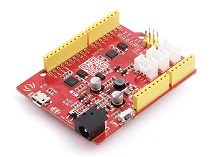
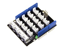
| Seeeduino V4.2 | Base Shield | Grove-3-Axis_Digitial_Compass_v2.0 |
|---|---|---|
|
|
|
| Get One Now | Get One Now | Get One Now |
-
Step 2. Connect Grove-3-Axis_Digitial_Compass_v2.0 to port I2C of Grove-Base Shield.
-
Step 3. Plug Grove - Base Shield into Seeeduino.
-
Step 4. Connect Seeeduino to PC via a USB cable.

If we don't have Grove Base Shield, We also can directly connect this module to Seeeduino as below.
| Seeeduino_v4 | Grove-3-Axis_Digitial_Compass_v2.0 |
|---|---|
| 5V | VCC |
| GND | GND |
| SDA | SDA |
| SCL | SCL |
Caution
Please plug the USB cable gently, otherwise you may damage the interface.Please use the USB cable with 4 wires inside, the 2 wires cable can't transfer data. If you are not sure about the wire you have, you can click here to buySoftware
Step 1. Download the library from Github.
Step 2. Refer How to install library to install library for Arduino.
Step 3. Create a new Arduino sketch and paste the codes below to it or open the code directly by the path: File->Examples->Grove_3_Axis_Compass_V2.0_BMM150-master->compass
Here is the code
/**
 * This example
*/

#include <Arduino.h>
#include <Wire.h>
// libraries
#include "bmm150.h"
#include "bmm150_defs.h"

BMM150 bmm = BMM150();

void setup()
{
  Serial.begin(9600);

  if(bmm.initialize() == BMM150_E_ID_NOT_CONFORM) {
    Serial.println("Chip ID can not read!");
    while(1);
  } else {
    Serial.println("Initialize done!");
  }

}

void loop()
{
  bmm150_mag_data value;
  bmm.read_mag_data();

  value.x = bmm.raw_mag_data.raw_datax;
  value.y = bmm.raw_mag_data.raw_datay;
  value.z = bmm.raw_mag_data.raw_dataz;

  float xyHeading = atan2(value.x, value.y);
  float zxHeading = atan2(value.z, value.x);
  float heading = xyHeading;

  if(heading < 0)
    heading += 2*PI;
  if(heading > 2*PI)
    heading -= 2*PI;
  float headingDegrees = heading * 180/M_PI;
  float xyHeadingDegrees = xyHeading * 180 / M_PI;
  float zxHeadingDegrees = zxHeading * 180 / M_PI;

  Serial.print("Heading: ");
  Serial.println(headingDegrees);

  delay(100);
}
Step 4. Upload the code. If you do not know how to upload the code, please check how to upload code.
Step 5. Open the serial monitor to receive the sensor's data

Step 6. Within these 3 seconds, please tilt and rotate the compass back and forth on every axis, as shown in the picture below.

The calibration period time can be changed through the parameter timeout in the fuction calibrate(uint16_t timeout).
The compass needs to be calibrated, otherwise you will get the inaccurate data! Please make sure you have done the Step 5.
Step 7. Finally, you will see the something like the following picture.

Heading value is in range of 0º ~ 360º, this value is for Y axis, 0º means Y axis points at North, 90º means Y axis points at West, 180º means Y axis points at South, 270º means Y points at East.
Enjoy your compass!
Play With Raspberry Pi (With Grove Base Hat for Raspberry Pi)
Hardware
- Step 1. Things used in this project:
| Raspberry pi | Grove Base Hat for RasPi | Grove - 3-axis compass |
|---|---|---|
|
|
|
| Get ONE Now | Get ONE Now | Get ONE Now |
- Step 2. Plug the Grove Base Hat into Raspberry.
- Step 3. Connect the 3-axis compass to I2C port of the Base Hat.
- Step 4. Connect the Raspberry Pi to PC through USB cable.

Software
-
Step 1. Follow Setting Software to configure the development environment and install the grove.py to your raspberry pi.
-
Step 2. Excute below commands to run the code.
virtualenv -p python3 env
source env/bin/activate
#enter commmand
grove_3_axis_compass_bmm150
Following is the grove_3_axis_compass_bmm150.py code.
from __future__ import print_function
import time
import bmm150
import math


def main():
    device = bmm150.BMM150()  # Bus number will default to 1
    while (1):
        x, y, z = device.read_mag_data()

        heading_rads = math.atan2(x, y)

        heading_degrees = math.degrees(heading_rads)

        print("Magnetometer x: {0:.2f}".format(x), end=' ')
        print(" y: {0:.2f}".format(y), end=' ')
        print(" z: {0:.2f}".format(z), end=' ')
        print(" uT")

        print('heading(axis_Y point to): {0:.2f} degree'.format(heading_degrees))
        time.sleep(.250)

if __name__ == '__main__':
    main()
If everything goes well, you will be able to see the following result
pi@raspberrypi:~/grove.py/grove $ grove_3_axis_compass_bmm150
Magnetometer x: -34.12  y: 36.71  z: -21.25  uT
heading(axis_Y point to): 317.10 degree
Magnetometer x: -34.49  y: 38.20  z: -16.32  uT
heading(axis_Y point to): 317.92 degree
Magnetometer x: -34.12  y: 38.20  z: -9.87  uT
heading(axis_Y point to): 318.23 degree
Magnetometer x: -32.64  y: 38.94  z: -5.69  uT
heading(axis_Y point to): 320.03 degree
Magnetometer x: -31.52  y: 38.20  z: -2.28  uT
heading(axis_Y point to): 320.47 degree
Magnetometer x: -29.67  y: 38.20  z: 0.38  uT
heading(axis_Y point to): 322.16 degree
Magnetometer x: -26.33  y: 38.20  z: 4.55  uT
heading(axis_Y point to): 325.42 degree
^CExiting
You can quit this program by simply press ++ctrl+c++.
Schematic Online Viewer
Resources
-
[Library] Grove-3_Axis_Compass_V2.0 lib
-
[PDF] BST-BMM150-Datasheet
-
[Zip] [Grove-3-Axis Digital Compass v2_Eagle File](https://files.seeedstudio.com/wiki/Grove-3-Axis_Digitial_Compass_v2.0/res/Eagle File.zip)
Tech Support & Product Discussion
Thank you for choosing our products! We are here to provide you with different support to ensure that your experience with our products is as smooth as possible. We offer several communication channels to cater to different preferences and needs.


