Grove - I2C Color Sensor

This module is based on the color sensor TCS3414CS with digital output I2C. Based on the 8*2 array of filtered photodiodes and 16-bit analog-to-digital converters, you can measure the color chromaticity of ambient light or the color of objects. Of the 16 photodiodes, 4 have red filters, 4 have green filters, 4 have blue filters and 4 have no filter(clear). With the synchronization input pin, an external pulsed light source can provide precise synchronous conversion control.
Please note that the latest version V2.0 has replaced the IC with TCS3472 and the old library has also been updated, If you are using the V2.0 version, please use the new library.
Features
- Grove compatible interface
- 16-Bit digital output with I2C
- SYNC Input Synchronizes Integration Cycle to Modulated Light Sources
- Operating temperature range -40°C to 85°C
- Programmable interrupt function with User-Defined Upper and lower threshold settings
- RoHS Compliant
More details about Grove modules please refer to Grove System
Specifications
| Parameter | Value/Range |
|---|---|
| PCB Size | 2.0 cm * 4.0 cm |
| Interface | 2.0mm pitch pin header |
| VCC | 3.3 - 6.0 V |
| I2C Speed | 400 kHz |
Platforms Supported
| Arduino | Raspberry Pi | |||
|---|---|---|---|---|
The platforms mentioned above as supported is/are an indication of the module's software or theoritical compatibility. We only provide software library or code examples for Arduino platform in most cases. It is not possible to provide software library / demo code for all possible MCU platforms. Hence, users have to write their own software library.
Getting Started
Following documents help in getting the user started with Grove.
Hardware Connections
Grove products have an eco system and all have the same connector which can plug onto the Grove Base Shield. Connect this module to the I2C port of Base Shield. However, you can also connect Grove - I2C Color Sensor to Arduino without Base Shield by jumper wires.
| Arduino UNO | Grove - I2C Color Sensor |
|---|---|
| 5V | VCC |
| GND | GND |
| SDA | SDA |
| SCL | SCL |
Software Installation
Download Arduino and install Arduino driver
Getting Started with Seeeduino/Arduino
Demos
This module can be used to detect the color of light source or the color of objects. When used to detect the color of the light source, the led switch should be turned off, and the light source should shine the sensor directly. When used to detect the color of things, the led should be on and you should put the object on the top of the enclosure closely. The theory of sensing the color of objects is Reflective Sensing Theory. Like the picture below.

Color Sensor Library
We have created a library to help you start playing quickly with the Seeeduino/Arduino, in this section we'll show you how to set up the library.
Setup
- Download the library code as a zip file from the Grove_I2C_Color_Sensor github page. If you are using the latest version V2.0(IC is TCS3472 ), please use this new library
- Unzip the downloaded file into your …/arduino/libraries.
- Rename the unzipped folder "Color_Sensor"
- Start the Arduino IDE (or restart if it is open).
Description of function
This is the most important/useful function in the library, we invite you to look at the .h and .cpp files yourself to see all the functions available.
Read RGB data through the library function
readRGB(int *red, int *green, int *blue)
- red: The variable address to save R.
- green: The variable address to save G.
- blue: The variable address to save B.
void loop()
{
    int red, green, blue;
    GroveColorSensor colorSensor;
    colorSensor.ledStatus = 1;            // When turn on the color sensor LED, ledStatus = 1; When turn off the color sensor LED, ledStatus = 0.
    while(1)
    {
        colorSensor.readRGB(&red, &green, &blue);    //Read RGB values to variables.
        delay(300);
        Serial.print("The RGB value are: RGB( ");
        Serial.print(red,DEC);
        Serial.print(", ");
        Serial.print(green,DEC);
        Serial.print(", ");
        Serial.print(blue,DEC);
        Serial.println(" )");
        colorSensor.clearInterrupt();
    }
}
Color Sensor Examples/Applications
This example shows how to use features of Grove - I2C Color Sensor and display the detected color with a Chainable RGB LED Grove.
If you haven't downloaded Grove-Chainable RGB LED library to your Arduino IDE before, please download and set up the library first.
- Open File->Examples->Color_Sensor->example->ColorSensorWithRGB-LED sketch for a complete example, or copy and paste code below to a new Arduino sketch.
Description: This example can measure the color chromaticity of ambient light or the color of objects, and via Chainable RGB LED Grove, display the detected color.
You also can use other display modules to display the detected color by Grove - I2C Color Sensor.
#include <Wire.h>
#include <GroveColorSensor.h>
#include <ChainableLED.h>

#define CLK_PIN   7
#define DATA_PIN  8
#define NUM_LEDS  1            //The number of Chainable RGB LED

ChainableLED leds(CLK_PIN, DATA_PIN, NUM_LEDS);

void setup()
{
    Serial.begin(9600);
    Wire.begin();
}

void loop()
{
    int red, green, blue;
    GroveColorSensor colorSensor;
    colorSensor.ledStatus = 1;            // When turn on the color sensor LED, ledStatus = 1; When turn off the color sensor LED, ledStatus = 0.
    while(1)
    {
        colorSensor.readRGB(&red, &green, &blue);    //Read RGB values to variables.
        delay(300);
        Serial.print("The RGB value are: RGB( ");
        Serial.print(red,DEC);
        Serial.print(", ");
        Serial.print(green,DEC);
        Serial.print(", ");
        Serial.print(blue,DEC);
        Serial.println(" )");
        colorSensor.clearInterrupt();
        for(int i = 0; i<NUM_LEDS; i++)
        {
            leds.setColorRGB(i, red, green, blue);
        }
    }
}
- Upload the code to the development board.
- Then Grove_-_Chainable_RGB_LED would display the color which is detected.
Play With Raspberry Pi
Hardware
- Step 1. Things used in this project:
| Raspberry pi | Grove Base Hat for RasPi | Grove-I2C_Color_Sensor |
|---|---|---|
|
|
|
| Get ONE Now | Get ONE Now | Get ONE Now |

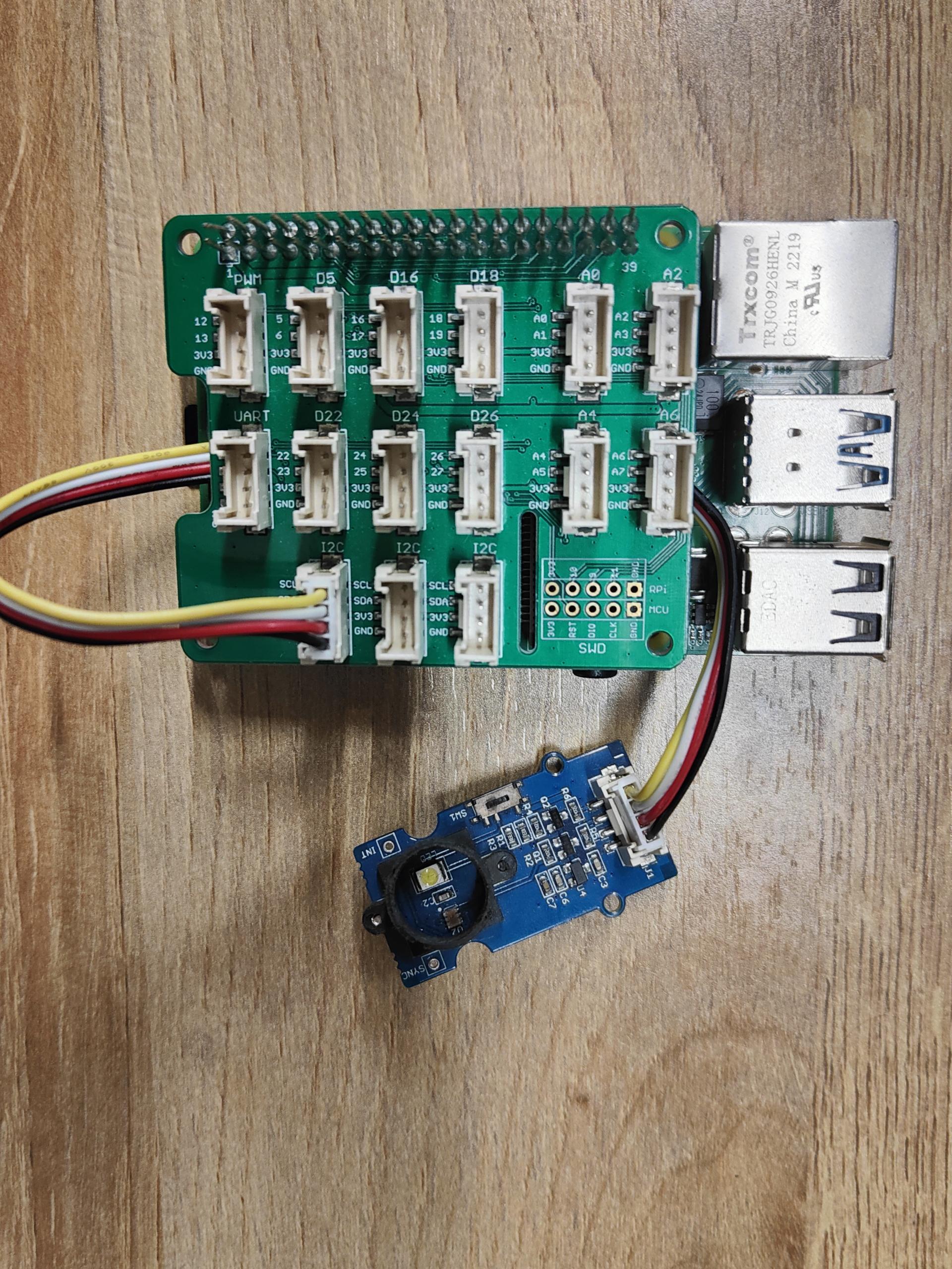
- Step 2. Plug the Grove Base Hat into Raspberry.
- Step 3. Connect the Grove-I2C_Color to the I2C port of the Base Hat.
- Step 4. Connect the Raspberry Pi to PC through USB cable.
Software
If you are using Raspberry Pi with Raspberrypi OS >= Bullseye, you have to use this command line only with Python3.
- Step 1. Follow Setting Software to configure the development environment.
- Step 2. Enter the relevant virtual environment.
source ~/grove_env/env/bin/activate
cd ~/grove_env/grove.py/grove
-
Step 3. Excute below command to run the code.
-
The following is to check thegrove_i2c_color_sensor_v2.py code.
less grove_i2c_color_sensor_v2.py
import time
from grove.i2c import Bus


_CMD      = 0x80
_AUTO     = 0x20

_ENABLE   = 0x00
_ATIME    = 0x01
_WTIME    = 0x03
_AILT     = 0x04
_AIHT     = 0x06
_PERS     = 0x0C
_CONFIG   = 0x0D
_CONTROL  = 0x0F
_ID       = 0x12
_STATUS   = 0x13
_CDATA    = 0x14
_RDATA    = 0x16
_GDATA    = 0x18
_BDATA    = 0x1A

_AIEN       = 0x10
_WEN        = 0x08
_AEN        = 0x02
_PON        = 0x01

_GAINS  = (1, 4, 16, 60)


class GroveI2cColorSensorV2:
    """Driver for Grove I2C Color Sensor (TCS34725)"""

    def __init__(self, bus=1, address=0x29):
        self.address = address
        self.bus = Bus(bus)

        self.awake = False

        if self.id not in (0x44, 0x4D):
            raise ValueError('Not find a Grove I2C Color Sensor V2')

        self.set_integration_time(24)
        self.set_gain(4)

    def wakeup(self):
        enable = self._read_byte(_ENABLE)
        self._write_byte(_ENABLE, enable | _PON | _AEN)
        time.sleep(0.0024)

        self.awake = True

    def sleep(self):
        enable = self._read_byte(_ENABLE)
        self._write_byte(_ENABLE, enable & ~_PON)

        self.awake = False

    def is_awake(self):
        return self._read_byte(_ENABLE) & _PON

    def set_wait_time(self, t):
        pass

    @property
    def id(self):
        return self._read_byte(_ID)

    @property
    def integration_time(self):
        steps = 256 - self._read_byte(_ATIME)
        return steps * 2.4

    def set_integration_time(self, t):
        """Set the integration time of the sensor"""
        if t < 2.4:
            t = 2.4
        elif t > 614.4:
            t = 614.4

        steps = int(t / 2.4)
        self._integration_time = steps * 2.4
        self._write_byte(_ATIME, 256 - steps)

    @property
    def gain(self):
        """The gain control. Should be 1, 4, 16, or 60.
        """
        return _GAINS[self._read_byte(_CONTROL)]

    def set_gain(self, gain):
        if gain in _GAINS:
            self._write_byte(_CONTROL, _GAINS.index(gain))

    @property
    def raw(self):
        """Read RGBC registers
        return 16 bits red, green, blue and clear data
        """

        if not self.awake:
            self.wakeup()

        while not self._valid():
            time.sleep(0.0024)

        data = tuple(self._read_word(reg) for reg in (_RDATA, _GDATA, _BDATA, _CDATA))
        return data

    @property
    def rgb(self):
        """Read the RGB color detected by the sensor.  Returns a 3-tuple of
        red, green, blue component values as bytes (0-255).
        """
        r, g, b, clear = self.raw
        if clear:
            r = int(255 * r / clear)
            g = int(255 * g / clear)
            b = int(255 * b / clear)
        else:
            r, g, b = 0, 0, 0
        return r, g, b

    def _valid(self):
        """Check if RGBC is valid"""
        return self._read_byte(_STATUS) & 0x01

    def _read_byte(self, address):
        command = _CMD | address
        return self.bus.read_byte_data(self.address, command)

    def _read_word(self, address):
        command = _CMD | _AUTO | address
        return self.bus.read_word_data(self.address, command)

    def _write_byte(self, address, data):
        command = _CMD | address
        self.bus.write_byte_data(self.address, command, data)

    def _write_word(self, address, data):
        command = _CMD | _AUTO | address
        data = [(data >> 8) & 0xFF, data & 0xFF]
        self.bus.write_i2c_block_data(self.address, command, data)


Grove = GroveI2cColorSensorV2


def main():
    sensor = GroveI2cColorSensorV2()

    print('Raw data of red-filtered, green-filtered, blue-filtered and unfiltered photodiodes')
    while True:
        # r, g, b = sensor.rgb
        r, g, b, clear = sensor.raw
        print((r, g, b, clear))
        time.sleep(1.0)

if __name__ == '__main__':
    main()
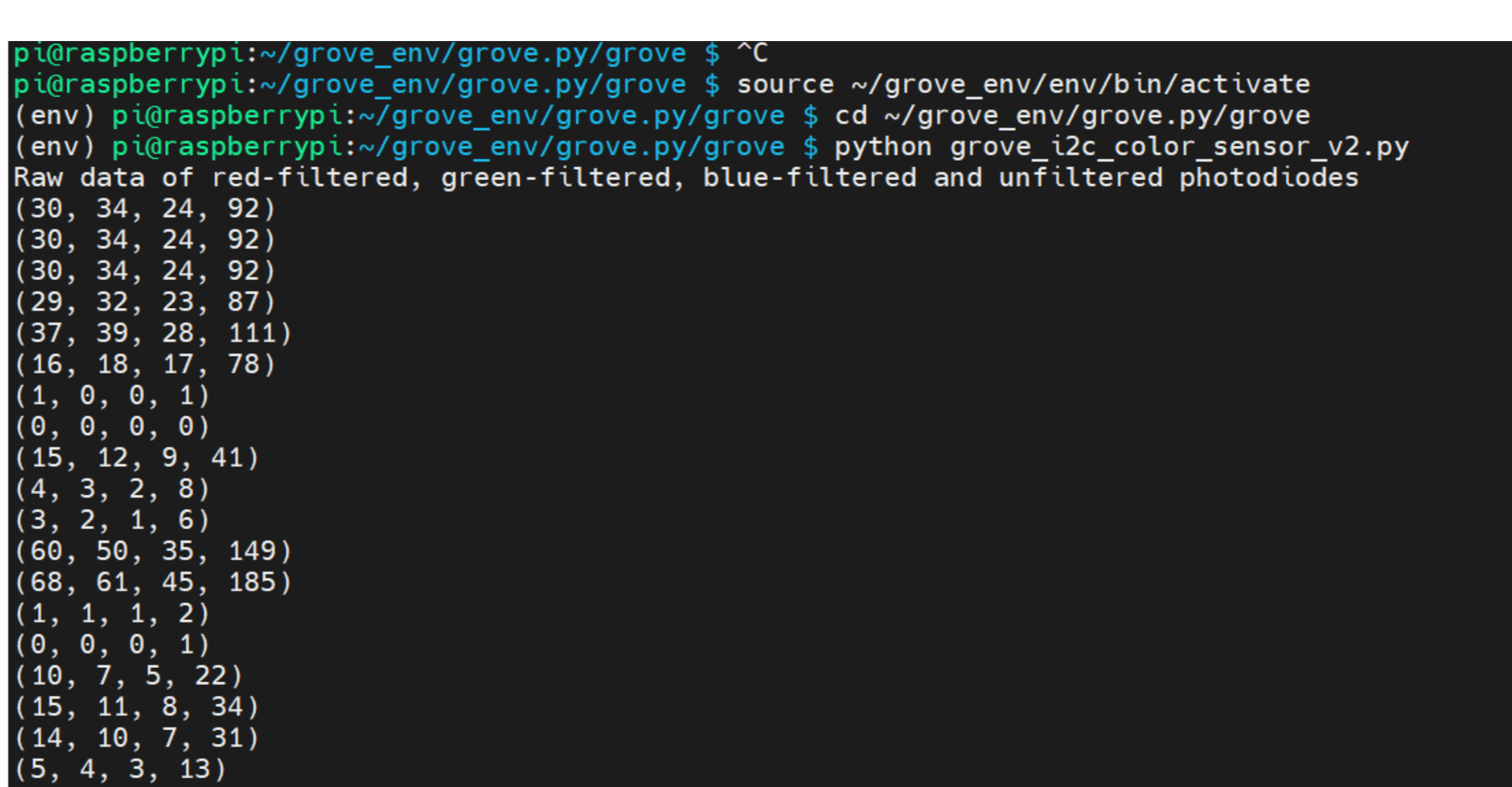
- Run this code
python grove_i2c_color_sensor_v2.py
If everything goes smoothly, you will see the following phenomenon.😄
Other Reference
This module is based on the color sensor TCS3414CS. The TCS3414CS digital color sensor returns data from four channels: red(R), green(G), blue(B) and clear(C)(non-filtered). The response from the red, green and blue channels (RGB) can be used to determine a particular source’s chromaticity coordinates (x, y). These standards are set by the Commission Internationale de l’Eclairage (CIE). The CIE is the main international organization concerned with color and color measurement.In order to acquire the color of a given object using TCS3414CS, we must first map the sensor response (RGB) to the CIE tristimulus values (XYZ). It is then necessary to calculate the chromaticity coordinates (x, y).
Chromaticity Calculation Process Overview
The equations to do the transformation:

Transformation Equations
- When we get coordinates (x, y), please reference the below figure so as to get the recommended color.

FAQs
Q1: How to understand the commands? For example, REG_GREEN_LOW = 0xD0
A1: From the attached picture, you can see what's in the command. When using byte protocol command, it must be like 0x80+ADDRESS. For example, REG_TIMING( 01h ) = 0x81 For byte and block read, the command should be 0xC0+ADDRESS, REG_GREEN_LOW( 10h ) = 0xD0.

Grove-I2C Color Sensor Eagle File V1.2
Grove-I2C Color Sensor Eagle File V2.0
Resources
- [Library]Library for Grove - I2C Color Sensor V1.2
- [Library]Library for Grove - I2C Color Sensor V2.0
- [Eagle]Grove-I2C Color Sensor Eagle File V1.2
- [Eagle]Grove-I2C Color Sensor Eagle File V2.0
- [Datasheet]TCS3414-A Datasheet
- [Datasheet]TCS3472 Datasheet
Tech Support & Product Discussion
Upgradable to Industrial Sensors
With the SenseCAP S2110 controller and S2100 data logger, you can easily turn the Grove into a LoRaWAN® sensor. Seeed not only helps you with prototyping but also offers you the possibility to expand your project with the SenseCAP series of robust industrial sensors.
The IP66 housing, Bluetooth configuration, compatibility with the global LoRaWAN® network, built-in 19 Ah battery, and powerful support from APP make the SenseCAP S210x the best choice for industrial applications. The series includes sensors for soil moisture, air temperature and humidity, light intensity, CO2, EC, and an 8-in-1 weather station. Try the latest SenseCAP S210x for your next successful industrial project.