Breakout for LinkIt Smart 7688

Due to the closure of MediaTek Labs, all related links have become invalid. If you need to download relevant files, please search for them on the following link: https://github.com/MediaTek-Labs.
Breakout for LinkIt Smart 7688 is a Grove port integrated expansion board for LinkItTM Smart 7688 development board. This breakout board will save a lot of work and makes prototyping easier through simplified wiring. It will assist a beginner to get started fast. It supports serial buses like I2C, UART. It comes with USB, Ethernet and 3.5mm Audio ports.
Features
-
Grove interface makes wiring easier and allows expansions with Grove modules.
-
USB host
-
Audio Output
-
Ethernet port
-
Cost-effective.
Application ideas
-
IoT/Gateway Device.
-
Robotics
-
Smart multimedia devices
-
Teaching and learning
Specification
| Input voltage | 5.0V(With USB Power port) |
| Operating voltage | 3.3V |
| Debug pins, Ethernet pins and USB type-A host pins conect with MT7688, Ohter pins connect with ATmega32U4. | |
Hardware Overview

Grove interface
Note that we will add the function of audio recording for this board in next version of this product.
This section will show those senior customers how to add recording funtion to this board.
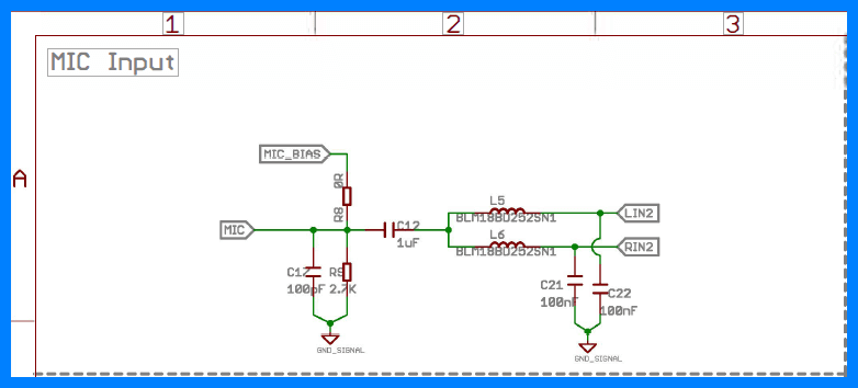
1.Download the schematic file at bottom of this page. Open the file named Breakout for LinkIt Smart7688 v1.0 brd.pdf, and find the section MIC Input. Remove following components inductor L6 and capacitor C21. This will added recording function to this board. Note this way only works as you use LinkIt Smart 7688 firmware version 0.9.3 and above.

2.For beginner, we recommend that you buy Breakout for LinkIt Smart 7688 v2.0 at bazaar.
Parts list
| Parts name | Quantity |
|---|---|
| Breakout for LinkIt Smart 7688 | 1PCS |
Get started
Material required
-
LinkIt Smart 7688 × 1
-
USB cable(type A to micro type-B) × 2
-
USB to Serial adapter × 1
-
Jumper wires × 3
-
Stereo(with 3.5 mm audio cable) × 1
-
USB flash driver(with audio file of MP3 format inside) × 1
Play music
- You can plug jumper wires to MT7688 UART2 port instead soldering them to Pin 8, Pin 9 and Pin GND.
- In rare cases, you might not connect to internet successfully, reboot the embedded OS.
2.Open a console with USB to Serial adapter.
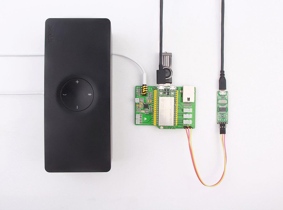
3.Connect all parts like follows:

4.Enter folder of USB by type cd /Media/USB-A1 in console.
5.Play music with utility Madplay(installed on OpenWRT) by typing madplay filename.mp3 into console.
6.Now you will hear the music.
Schematic Online Viewer
Resources
Tech Support & Product Discussion
Thank you for choosing our products! We are here to provide you with different support to ensure that your experience with our products is as smooth as possible. We offer several communication channels to cater to different preferences and needs.
