Getting Started with Dual Gigabit Ethernet Carrier Board for Raspberry Pi Compute Module 4

The Dual Gigabit Carrier Board powered by Raspberry Pi Compute Module 4 is equipped with Dual Gigabit Ethernet ports and dual USB 3.0 ports, making it suitable for soft router applications, while keeping the hardware to minimal.
It features a variety of I/O peripherals such as MIPI CSI, MIPI DSI, micro-HDMI to connect displays/ cameras, a standard 9-pin USB 3.0 header for more USB expansion, a micro-SD card slot, and an FPC connector, while maintaining a compact form factor! This board is ideal for HTPC makers, Linux developers, software router enthusiasts, and the majority of regular Raspberry Pi users.
Features
- Compact size (75x64x21mm) with rich I/O peripherals
- Dual Gigabit Ethernet connectors for soft router applications
- Camera/ display connectivity using MIPI CSI, MIPI DSI and micro-HDMI interfaces
- Onboard dual USB 3.0 with an additional USB 3.0 9-pin header for more external ports
- Micro-SD Card slot to load system image for non-eMMC version of CM4
- More Expandability via FPC Connector (I2C, SPI)
- External fan support with fan power connector
- Power using USB Type-C
Specifications
| Specification | Details |
|---|---|
| Networking | Dual Gigabit Ethernet Connectors |
| USB 3.0 to GbE (Gigabit Ethernet Bridge) | Microchip's LAN7800 |
| USB | 2 x USB 3.0 Ports 1 x USB 3.0 9-Pin Header |
| Storage | Micro-SD Card Slot (load system Image for non-eMMC CM4 version) |
| Camera | 1 x MIPI CSI Connector |
| Display | 1 x MIPI DSI Connector 1 x Micro HDMI Connector |
| FPC | Interface for I2C and SPI |
| External Fan | Power connector for fan |
| Power | 5V/3A using USB Type-C Port |
| Dimensions | 75x64x21mm |
| Weight | 43g |
Due to the high level of integration of this product, it must be used with a CM4 heat sink. Otherwise it may cause USB or Ethernet instability
Hardware Overview

Hardware Introduction
200-Pin Interface for Raspberry Pi Compute Module 4
This carrier board has a 200-pin interface with 2 rows of 100 pins each, so that you can connect a Raspberry Pi Compute Module 4 and realize your projects!
Schematics

Tip: Click here for a higher resolution image
Dual Gigabit Ethernet Ports
This carrier board features 2 x Gigabit Ethernet Ports (RJ45). One Ethernet Port is connected to the Gigabit Ethernet PHY of the CM4 module which is based on Broadcom BCM54210PE. On the the hand, the other Gigabit Ethernet Port is connected to Microchip's LAN7800 which is a USB 3.0 to GbE (Gigabit Ethernet Bridge). The USB 3.0 interface here is extended from the PCIe interface of the CM4 Module. Also, both ports can support speeds up to 1Gbps.
Schematics of Dual Gigabit Ethernet Ports
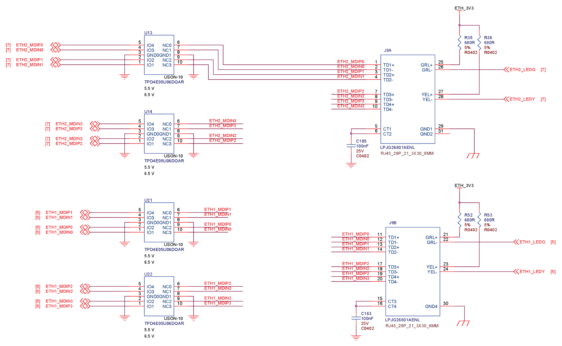
Tip: Click here for a higher resolution image
Schematics of USB 3.0 to GbE (Gigabit Ethernet Bridge)
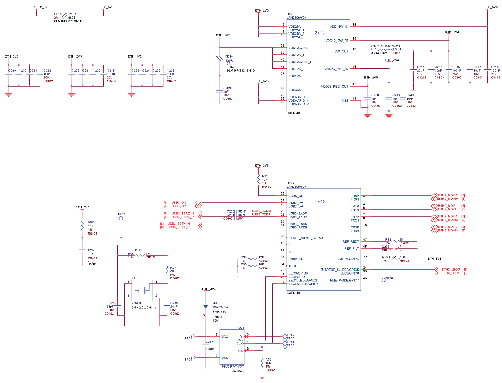
Tip: Click here for a higher resolution image
CSI Camera Interface
This has a MIPI CSI camera interface, and you can connect a camera via a 15-pin CSI flex cable. This camera interface can be used for object detection and machine learning applications.
Schematics

Tip: Click here for a higher resolution image
DSI Display Interface
This has a MIPI DSI display interface, and you can connect a display via a 15-pin DSI flex cable. This display interface can be used for interacting with the carrier board.
Schematics
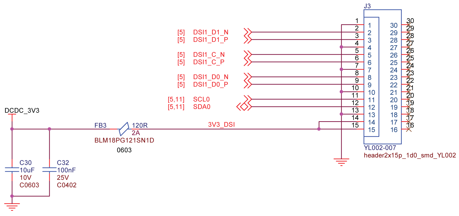
Tip: Click here for a higher resolution image
FPC Interface
There is an 8-pin FPC interface on this carrier board with 0.5mm Pitch H2.5. You can use this interface to connect additional hardware such as cameras and displays to the carrier board.
Specifications
- Rated Current: 0.5A
- Rated Voltage: 50V
- Withstand Voltage: 500V
- Contact Resistance: 20mΩ
- Insulation Resistance: 800mΩ
- Working Temperature: -20°C ~ +85°C
Schematics


Dual USB 3.0 Ports and 9-Pin Header
Compute Module 4 natively has only a USB 2.0 interface. However, we have used the existing PCIe interface on the CM4 and expanded it into a USB 3.0 interface with 2 x USB 3.0 Ports. These USB ports offer a transfer speed up to 5Gbps.
Additionally there is a USB 3.0 9-pin header and you can connect even more USB devices using this header.
You can first connect a 9-Pin Female to 20-Pin Female Adapter to the 9-Pin header on this board and then connect a 20-Pin Male to USB3.0 Adapter to the previous 20-pin female header. We need these 2 products because currently 9-Pin to USB3.0 Adapter is not available in the market, and only 9-Pin to USB2.0 Adapter is available.

Note: If you want to connect a 5V fan to this board using jumper wires, you can connect the positive end (+) of fan to VBUS and negative end(-) of fan to GND pins.

Schematics of USB 3.0 HOST

Tip: Click here for a higher resolution image
Schematics of PCIe to USB 3.0

Tip: Click here for a higher resolution image
Micro HDMI Port
There is a micro HDMI port on the carrier board and you can use it to connect to HDMI displays via a micro HDMI to standard HDMI cable. It supports video up to 4K resolution at 60fps.
Schematics
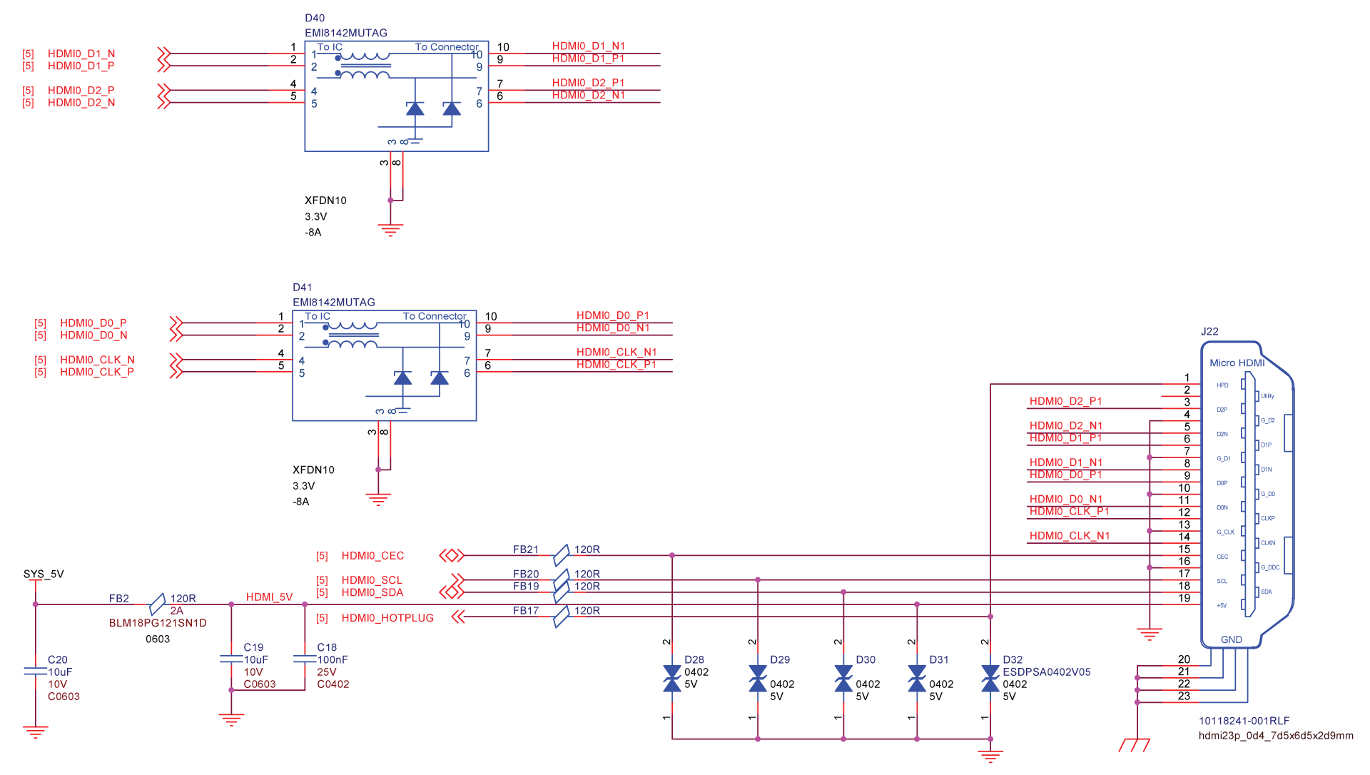
Tip: Click here for a higher resolution image
UART IO
There is a 4-pin interface on the carrier board for UART communications. You can use this interface and log in to the Raspberry Pi OS directly using a USB to Serial Adapter Cable. It has the pins: TX, RX, 3V3, GND.

Boot Mode Pin
This 3-pin interface is used when you want to make the carrier board as a USB Device. Once you short the GND and BOOT pins, you can access the eMMC storage or the micro-SD card storage using a HOST PC.

Reset Button
This button is used to reset the CM4. It acts as a hardware reboot.
Schematics

Micro - SD Card Slot
This is equipped with a micro-sd card slot. This is useful when you want to install the operating system on to a micro-SD card, while the CM4 module without eMMC is used. It is recommeded to use a card with a minimum of at least 8GB.
Schematics

Tip: Click here for a higher resolution image
USB Type-C Port
The USB Type-C Port on the carrier board can be used to power the carrier board using 5V/3A. However it can also be used to act as a USB Device where you can connect the carrier board to a HOST PC and the carrier board will act as a USB Mass Storage Device. In here, you will be able to access the onboard eMMC and the connected micro-SD card of the carrier board via the PC.
Schematics of USB Type-C as USB Device

Tip: Click here for a higher resolution image
Schematics of Power Management
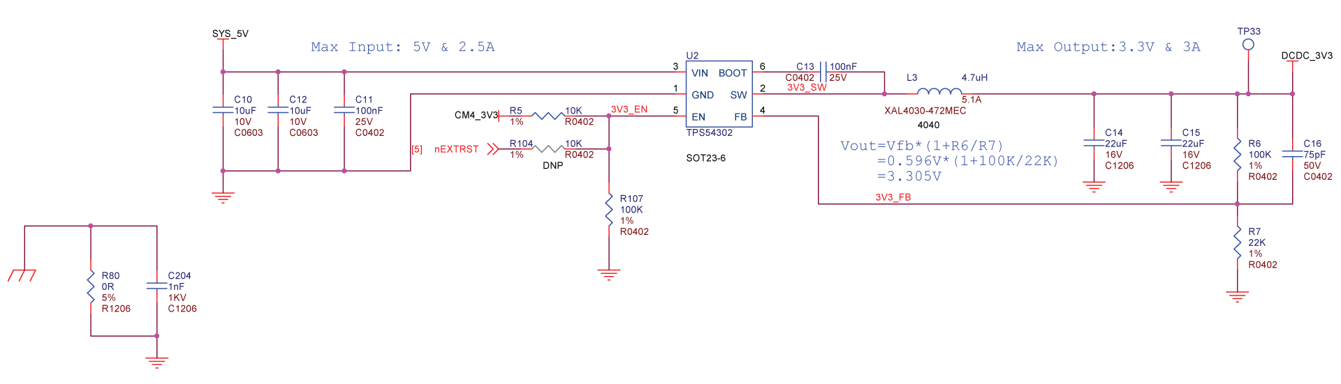
Tip: Click here for a higher resolution image
4-Pin Fan Connector
You can connect a 4-pin PWM fan to this connector and control it using software.
Schematics

Tip: Click here for a higher resolution image
Power and Working LEDs
The carrier board has 3 LEDs. One is to indicate that it is powered on and it lights up in Blue, whereas the other 2 LEDs is to indicate the working status of the carrier board and they light up in Green and White.
Schematics

Tip: Click here for a higher resolution image
Getting Started - Hardware Required
You need to prepare the following hardware before getting started with the Dual Gigabit Ethernet Carrier Board for RPi CM4
- Dual Gigabit Ethernet Carrier Board for RPi CM4
- 16GB (or more) micro-SD card
- Micro-SD card reader
- Computer (PC/Mac/Linux)
- Power adapter (5V/3A)
- USB Type-C cable
- USB to serial converter, Ethernet cable (optional)
Getting Started - Software Set Up
Flash Raspberry Pi OS
Now we need to flash Raspberry Pi OS on to a micro-SD card (for non-eMMC version) or to eMMC storage (for eMMC version), so that it can run on the Raspberry Pi Compute Module 4.
Flash to Micro-SD Card (CM4 Non-eMMC Version)
If you have a Compute Module 4 without eMMC, then you need to insert a micro-SD and flash the Raspberry Pi OS. Follow the steps below according to your operating system.
-
Step 1. Insert a micro-SD card to the computer using a micro-SD card reader connected to the computer, or by using a built-in card reader on a laptop
-
Step 2. Download Raspberry Pi Imager software by visiting this link
Note: You can choose to download for either Windows, Mac or Ubuntu
- Step 3. Open Raspberry Pi Imager software

-
Step 4. Click CHOOSE OS and select the latest version of the Raspberry Pi OS (32-bit)
-
Step 5. Click CHOOSE STORAGE and select the connected micro-SD card
-
Step 6. Finally, click WRITE

Please wait a few minutes until the flashing process is complete.
Flash to eMMC (CM4 eMMC Version)
If you have a Compute Module 4 with eMMC, then you can directly flash the Raspberry Pi OS on to the eMMC storage. Once the necessary drivers are installed, you just have to connect the USB Type-C port of the CM4 in to your PC, and it will show as an external drive. Follow the steps below according to your operating system.
For Windows
-
Step 1. Download and run this installer to install the necessary drivers and the boot tool
-
Step 2. Connect a jumper wire between Boot and GND pins as follows to enable the programming mode
- Step 3. Connect Carrier Board to the PC via USB Type-C cable
Windows will now find the hardware and install the necessary drivers
-
Step 4. Search for rpiboot tool that we installed before and open it
-
Step 5. Open file explorer and you will see the eMMC of the Computer Module 4 shown as a USB mass storage device
-
Step 6. Download Raspberry Pi Imager software by visiting this link
-
Step 7. Open Raspberry Pi Imager software
-
Step 8. Click CHOOSE OS and select the latest version of the Raspberry Pi OS (32-bit)
-
Step 9. Click CHOOSE STORAGE and select the connected eMMC drive
-
Step 10. Finally, click WRITE
Please wait a few minutes until the flashing process is complete.
For Mac/Linux
We will use Git to obtain the rpiboot source code, so make sure Git is installed
- Step 1. Open a Terminal window and type the following to update the packages list
sudo apt-get update
- Step 2. Install Git by the following command
sudo apt install git
- Step 3. Git might produce an error if the date is not set properly. Type the following to correct this
sudo date MMDDhhmm
NOTE: Where MM is the month, DD is the date, and hh and mm are hours and minutes respectively.
- Step 4. Clone the usbboot tool repository
git clone --depth=1 https://github.com/raspberrypi/usbboot
cd usbboot
- Step 5. Enter the following to install libusb
sudo apt install libusb-1.0-0-dev
- Step 6. Build and install the usbboot tool
make
- Step 7. Run the usbboot tool and it will wait for a connection
sudo ./rpiboot
- Step 8. Connect a jumper wire between Boot and GND pins as follows to enable the programming mode
-
Step 9. Connect Carrier Board to the PC via USB Type-C cable
-
Step 10. Download Raspberry Pi Imager software by visiting this link
-
Step 11. Open Raspberry Pi Imager software
-
Step 12. Click CHOOSE OS and select the latest version of the Raspberry Pi OS (32-bit)
-
Step 13. Click CHOOSE STORAGE and select the connected eMMC drive
-
Step 14. Finally, click WRITE
Please wait a few minutes until the flashing process is complete.
Log in to Raspberry Pi OS
Method 1: Using SSH over Wi-Fi
If you want to log in to the Raspberry Pi OS using SSH over Wi-Fi, you can follow the steps below. Please follow according to your operating system
For Windows
-
Step 1. Insert the micro-SD card (with Raspberry Pi OS already installed) to the computer using a micro-SD card reader connected to the computer, or by using a built-in card reader on a laptop
-
Step 2. Open Notepad and type the following
country=CN
ctrl_interface=DIR=/var/run/wpa_supplicant GROUP=netdev
update_config=1

network={
ssid="WiFi-name"
psk="WiFi-password"
key_mgmt=WPA-PSK
priority=1
}
NOTE: The Country Code (country) should be set to the ISO/IEC alpha2 code for the country in which you are using your board.
-
Step 3. Click
File > Save -
Step 4. Navigate to the connected drive name of the micro-SD card

- Step 5. Type the file name as wpa_supplicant.conf, select Save as type as All Files and click Save

- Step 6. Open Command Prompt and navigate to the micro-SD card
Example:
C:\Users\user> F:
F:\>
- Step 7. Once you are inside the micro-SD card, create an empty file called SSH by typing typing the following
echo > ssh
Note: This is done to enable SSH on the Raspberry Pi OS
-
Step 8. Eject the micro-SD card from PC and insert it into the Dual Gigabit Ethernet Carrier Board
-
Step 9. Connect a USB Typc-C cable to the Type-C port on the carrier board and connect the other end of the Type-C cable to a power adapter and turn it on
-
Step 10. Download and install Putty by visiting this link
Note: Putty is an SSH and telnet client where you can use it to connect to the Carrier Board via SSH
-
Step 11. Open Putty to connect the PC to the Carrier Board
-
Step 12. Select SSH under the Connection Type
-
Step 13. Under Host Name. type raspberrypi.local and leave the Port as 22

-
Step 14. Click Open
-
Step 15. On the Putty window, enter the login details as follows
- Username: pi
- Password: raspberry
- Step 16. If you have sucessfully logged into the Raspberry Pi OS, you will see the following output

For Mac/Linux
-
Step 1. Insert the micro-SD card (with Raspberry Pi OS already installed) to the computer using a micro-SD card reader connected to the computer, or by using a built-in card reader on a laptop
-
Step 2. Open Terminal and navigate to the micro-SD card
Example:
cd /media/user/boot
NOTE: In /media/user/boot, replace user with your PC username
- Step 3. Once you are inside the micro-SD card, create a file called wpa_supplicant.conf and open it
nano wpa_supplicant.conf
- Step 4. Type the following content into the file
country=CN
ctrl_interface=DIR=/var/run/wpa_supplicant GROUP=netdev
update_config=1

network={
ssid="WiFi-name"
psk="WiFi-password"
key_mgmt=WPA-PSK
priority=1
}
NOTE: The Country Code (country) should be set to the ISO/IEC alpha2 code for the country in which you are using your board.
-
Step 5. Press Ctrl + x on the keyboard to save the file, and then press y and Enter to confirm the changes
-
Step 6. While you are inside the boot drive, create an empty file called SSH by typing typing the following
touch ssh
NOTE: This is done to enable SSH on the Raspberry Pi OS
-
Step 7. Eject the micro-SD card from PC and insert it into the Dual Gigabit Ethernet Carrier Board
-
Step 8. Connect a USB Typc-C cable to the Type-C port on the carrier board and connect the other end of the Type-C cable to a power adapter and turn it on
-
Step 9. Open Terminal on the PC again and type the following
- Step 10. Type yes for the following message
ECDSA key fingerprint is SHA256:XXXXXXX.
Are you sure you want to continue connecting (yes/no/[fingerprint])?
- Step 11. When it asks for the password, type the following
raspberry
- Step 12. If you have sucessfully logged into the Raspberry Pi OS, you will see the following output

Method 2: Using SSH over Ethernet
If you want to log in to the Raspberry Pi OS using SSH over Ethernet, you can follow the steps below. Please follow according to your operating system
For Windows
-
Step 1. Insert the micro-SD card (with Raspberry Pi OS already installed) to the computer using a micro-SD card reader connected to the computer, or by using a built-in card reader on a laptop
-
Step 2. Open Command Prompt and navigate to the micro-SD card
Example:
C:\Users\user> F:
F:\>
- Step 3. Once you are inside the micro-SD card, create an empty file called SSH by typing typing the following
echo > ssh
This is done to enable SSH on the Raspberry Pi OS
-
Step 4. Eject the micro-SD card from PC and insert it into the Dual Gigabit Ethernet Carrier Board
-
Step 5. Connect a USB Typc-C cable to the Type-C port on the carrier board and connect an Ethernet Cable to one of the Ethernet Ports on the Carrier Board
-
Step 6. Connect the other end of the Ethernet cable to a router and also connect the other end of the Type-C cable to a power adapter and turn it on
-
Step 7. Download and install Putty by visiting this link
Note: Putty is an SSH and telnet client where you can use it to connect to the Carrier Board via SSH
-
Step 8. Open Putty to connect the PC to the Carrier Board
-
Step 9. Select SSH under the Connection Type
-
Step 10. Under Host Name. type raspberrypi.local and leave the Port as 22
-
Step 11. Click Open
-
Step 12. On the Putty window, enter the login details as follows
- Username: pi
- Password: raspberry
- Step 13. If you have sucessfully logged into the Raspberry Pi OS, you will see the following output
For Mac/Linux
-
Step 1. Insert the micro-SD card (with Raspberry Pi OS already installed) to the computer using a micro-SD card reader connected to the computer, or by using a built-in card reader on a laptop
-
Step 2. Open Terminal and navigate to the micro-SD card
Example:
cd /media/user/boot
NOTE: In /media/user/boot, replace user with your PC username
- Step 3. Once you are inside the micro-SD card, create an empty file called SSH by typing typing the following
touch ssh
NOTE: This is done to enable SSH on the Raspberry Pi OS
-
Step 4. Eject the micro-SD card from PC and insert it into the Dual Gigabit Ethernet Carrier Board
-
Step 5. Connect a USB Typc-C cable to the Type-C port on the carrier board and connect an Ethernet Cable to one of the Ethernet Ports on the Carrier Board
-
Step 6. Connect the other end of the Ethernet cable to a router and also connect the other end of the Type-C cable to a power adapter and turn it on
-
Step 7. Open Terminal on the PC again and type the following
- Step 8. Type yes for the following message
ECDSA key fingerprint is SHA256:XXXXXXX.
Are you sure you want to continue connecting (yes/no/[fingerprint])?
- Step 9. When it asks for the password, type the following
raspberry
- Step 10. If you have sucessfully logged into the Raspberry Pi OS, you will see the following output
Method 3: Using USB to Serial Converter
For Windows
If you have a USB to Serial Converter, you can use the following steps to log in to Raspberry Pi OS
-
Step 1. Insert the micro-SD card (with Raspberry Pi OS already installed) to the computer using a micro-SD card reader connected to the computer, or by using a built-in card reader on a laptop
-
Step 2. Open File Explorer and navigate to the connected micro-SD card
-
Step 3. Open config.txt file and add the following line at last
enable_uart=1
This is to enable UART communication between PC and Carrier Board
-
Step 4. Click
File > Saveto save your configuration -
Step 5. Eject the micro-SD card from PC and insert it back into the Carrier Board
-
Step 6. Solder a 4-Pin Male Header to the UART IO on the Carrier Board
-
Step 7. Connect the jumper wires from the USB to Serial Converter to the UART IO pin header on the Carrier Board as follows
-
Step 8. Connect the USB to Serial Converter to the PC
-
Step 9. Open Device Manager by typing Device Manager in the windows search box
-
Step 10. Click on the drop-down arrow from Ports (COM & LPT) and find the name of the connected serial port (ex: COM42)

- Step 11. Download and install Putty by visiting this link
Note: Putty is an SSH and telnet client where you can use it to connect to the Carrier Board via SSH. You can skip this step if you already have Putty installed
-
Step 12. Open Putty to connect the PC to the Carrier Board
-
Step 13. Select Serial under the Connection Type
-
Step 14. Configure the settings as follows:
- Serial line: COM4 (choose your COM port)
- Speed: 115200

-
Step 15. Click Open
-
Step 16. On the Putty window, enter the login details as follows
- Username: pi
- Password: raspberry
- Step 17. If you have sucessfully logged into the Raspberry Pi OS, you will see the following output
For Mac/Linux
If you have a USB to Serial Converter, you can use the following steps to log in to Raspberry Pi OS
-
Step 1. Insert the micro-SD card (with Raspberry Pi OS already installed) to the computer using a micro-SD card reader connected to the computer, or by using a built-in card reader on a laptop
-
Step 2. Open boot drive and navigate to the connected micro-SD card
-
Step 3. Open config.txt file and add the following line at the en
enable_uart=1
NOTE: This is to enable UART communication between PC and Carrier Board
-
Step 4. Click
File > Saveto save your configuration -
Step 5. Eject the micro-SD card from PC and insert it back into the Carrier Board
-
Step 6. Solder a 4-Pin Male Header to the UART IO on the Carrier Board as follows
-
Step 7. Connect the jumper wires from the USB to Serial Converter to the UART IO pin header on the Carrier Board
-
Step 8. Connect the USB to Serial Converter to the PC
-
Step 9. Open a terminal window on Mac/Linux
-
Step 10. Type the following to update the packages list
sudo apt-get update
- Step 11. Type the following to install minicom
sudo apt-get install minicom
- Step 12. Type the following in the terminal to view the connected serial devices
dmesg | grep tty
Ex:
[ 1562.048241] cdc_acm 1-3:1.0: ttyACM0: USB ACM device
- Step 13. Connect to the serial device by typing the following
minicom -D /dev/ttyACM0 -b 115200
Note: The baud rate is set to 115200
- Step 14. After the hardware connections mentioned above, turn on the power from the wall power socket to power on the Carrier Board
Now you have successfully logged into Raspberry Pi OS.
Method 4: Using Keyboard, Mouse and Display
If you have an HDMI Display. micro-HDMI to full-size HDMI cable, keyboard and a mouse, you can connect them to the Dual Gigabit Ethernet Carrier Board and log in to the Raspberry Pi OS.
(draw a diagram - not very important)
USB Ports Configuration
By default, the 2 USB 3.0 Ports are disabled to save power on the CM4 are therefore they are not readily accessible. However the USB 3.0 9-Pin Header is accessible out of the box.
If you want to enable the 2 USB 3.0 Ports, you need to add a line at the end of the config.txt file located inside the /boot directory
There are 2 ways of doing this:
Method 1: Modify the file from micro-SD card connected to PC
-
Step 1. Insert the micro-SD card (with Raspberry Pi OS already installed) to the computer
-
Step 2. Open File Explorer and navigate to the connected micro-SD card
-
Step 3. Open config.txt file and add the following line at the end
dtoverlay=dwc2,dr_mode=host
- Step 4. Save the file
Method 2: Modify the file from Carrier Board
-
Step 1. Insert the micro-SD card to the Carrier Board and turn it on
-
Step 2. Log in to Raspberry Pi OS using any of the methods explained before
-
Step 3. Navigate to the boot directory by typing the following
cd /boot
- Step 4. Open config.txt using nano text editor
sudo nano config.txt
- Step 5. Add the following line at the end
dtoverlay=dwc2,dr_mode=host
- Step 6. Press Ctrl + X, press Y and then press Enter on the keyboard to save the file
USB Ports Speed Test
If you want to test the speed of the USB Ports, you can execute the following commands on Raspberry Pi OS Terminal
sudo dd if=/dev/sda1 of=/dev/null bs=512k count=5000
The output will be as follows
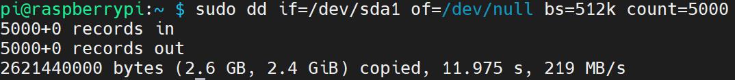
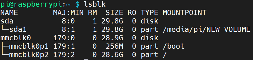
NOTE: In if=/dev/sda1, sda1 is the connected USB drive. You can find it by typing lsblk as follows
Ethernet Ports Configuration
Once you flash the Raspberry Pi OS onto the CM4 module, you will get the full Gigabit speed (1Gbps) only on the Ethernet port connected to the Gigabit Ethernet PHY of the CM4 module which is based on Broadcom BCM54210PE (right-side port). The port which is connected to the Microchip's LAN7800 USB 3.0 to GbE (Gigabit Ethernet Bridge) (left-side port), will not provide the full speed of 1Gbps, but rather a much reduced speed. This is because the lan78xx driver in the raspberry core is not up to date.
Follow the steps below to install a script and fix this issue:
-
Step 1. Enter Raspberry Pi OS Terminal window
-
Step 2. Type the following to download the repo
git clone https://github.com/Seeed-Studio/seeed-linux-dtoverlays.git
- Step 3. Enter the repo directory
cd seeed-linux-dtoverlays
- Step 4. Type the following to install the scipt
sudo ./scripts/cm4_lan7800.sh
- Step 5. Reboot the carrier board
sudo reboot
- Step 6. Type the following to check the status of the installation
dmesg | grep lan
If you see the below output, your driver is successfully working now

Note: If you want to access the help usage, type sudo ./cm4_lan7800.sh -h

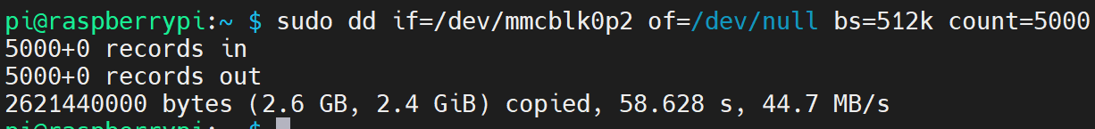
SD Card Speed Test
Access the Raspberry Pi OS terminal window and execute the following command
sudo dd if=/dev/mmcblk0p2 of=/dev/null bs=512k count=5000
You will see the output as follows
DSI and CSI Connectors Configuration
If you want to connect a display through DSI interface, and a camera through CSI interface on the Carrier Board, please follow the steps below
-
Step 1. Connect the display to the DSI1 port and connect the camera to the CSI1 port on the Carrier Board as follows
-
Step 2. Enable the display and camera by executing the following inside the terminal window of Raspberry Pi OS
sudo wget https://datasheets.raspberrypi.org/cmio/dt-blob-disp1-cam1.bin -O /boot/dt-blob.bin
Note: Here the configuration method is chosen from cmio-display and raspistill
- Step 3. Run the commands below to take a photo from the camera and preview on the display
raspistill -v -o test.jpg

I2C Configuration
Hardware Set Up
If you want to connect an I2C device to the FPC interface, please follow the connections:

Software Set Up
You can connect I2C devices to the 8-pin FPC connector and control them using Raspberry Pi OS.
- Step 1. Visit Raspberry Pi software configuration tool
sudo raspi-config
-
Step 2. Go to
Interface Options > I2Cand press Enter -
Step 3. Select Yes to enable I2C
-
Step 4. Reboot the carrier board
sudo reboot
I2C Debugging
-
Step 1. Connect an I2C device to the 8-pin FPC connector of the carrier board
-
Step 2. List all the available I2C busses
i2cdetect -l

- Step 3. Immediately scan the standard addresses on I2C bus 1 (i2c-1), using the default method for each address
i2cdetect -y 1
Note 1 represents the I2C bus number

The above picture shows a device detected with an I2C address of 0x5c
- Step 4. Read the contents of the register by typing the following
i2cget -f -y 1 0x5c 0x0f
- -y disables interactive mode. By default, i2cdetect will wait for a confirmation from the user before messing with the I2C bus. When this flag is used, it will perform the operation directly
- 1 represents the I2C bus number
- 0x5c represents the I2C device address
- 0x0f represents the memory address
The output will be as follows

- Step 5. Write data to register by typing the following
i2cset -y 1 0x5c 0x11 0x10
- -y disables interactive mode. By default, i2cdetect will wait for a confirmation from the user before messing with the I2C bus. When this flag is used, it will perform the operation directly
- 1 represents the I2C bus number
- 0x5c represents the I2C device address
- 0x11 represents the memory address
- 0x10 represents the specific content in the memory address
- Step 6. Read all register values by typing the following
i2cdump -y 1 0x5c
- -y disables interactive mode. By default, i2cdetect will wait for a confirmation from the user before messing with the I2C bus. When this flag is used, it will perform the operation directly
- 1 represents the I2C bus number
- 0x5c represents the I2C device address
The output will be as follows

SPI Configuration
Hardware Set Up
If you want to connect an SPI device to the FPC interface, please follow the connections:

Software Set Up
You can connect SPI devices to the 8-pin FPC connector and control them using Raspberry Pi OS.
- Step 1. Visit Raspberry Pi software configuration tool
sudo raspi-config
-
Step 2. Go to
Interface Options > SPIand press Enter -
Step 3. Select Yes to enable SPI
-
Step 4. Reboot the carrier board
sudo reboot
SPI Debugging
-
Step 1. Connect an SPI device to the 8-pin FPC connector of the carrier board
-
Step 2. List all the available SPI devices
ls /dev/spi*
The output will be as follows

-
Step 3. Insert micro-SD card into PC
-
Step 4. Navigate to the boot drive
-
Step 5. Download this file and move into boot drive
-
Step 6. Unplug micro-SD card from PC and plug into carrier board
-
Step 7. Turn on carrier board and navigate into the boot directory
cd /boot
- Step 8. Short GPIO 10 (Pin 6) and GPIO 9 (Pin 7) using a jumper wire
Note: Here we short-circuit MOSI and MISO pins
- Step 9. Run the the following SPI test tool
./spidev_test -D /dev/spidev0.0 -v -p hello
If you see the following output, SPI is working properly

Resources
-
[PDF] Dual Gigabit Ethernet Carrier Board for Raspberry Pi CM4 Schematics
-
[Web Page] Raspberry Pi Official Documentation
Tech Support & Product Discussion
Thank you for choosing our products! We are here to provide you with different support to ensure that your experience with our products is as smooth as possible. We offer several communication channels to cater to different preferences and needs.