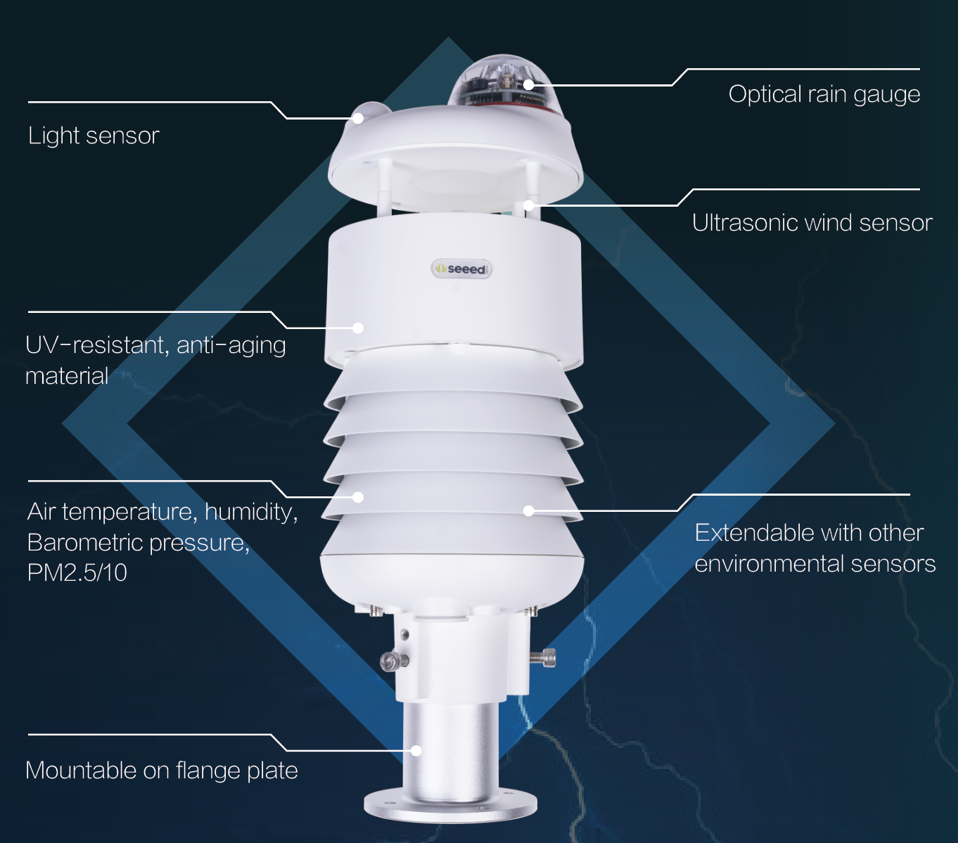
Getting Started with SenseCAP ONE Compact Weather Sensor
Pre-Installation
Installation
Installation
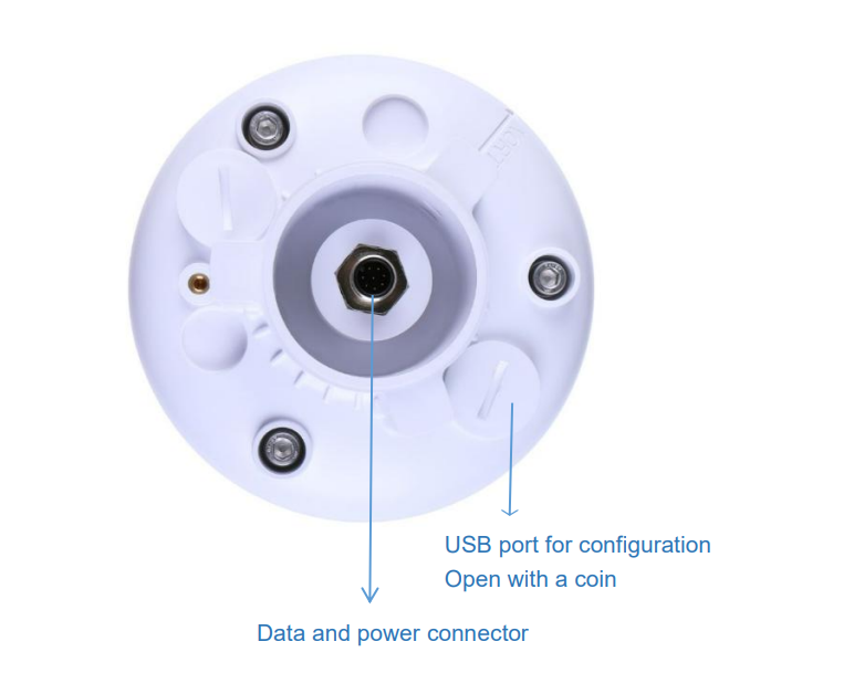
Device Interface Introduction
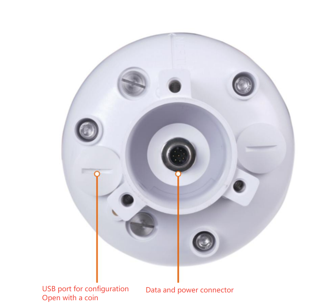
There are two connectors at the bottom of the device.
-
USB Type-C interface allows you to connect your computer with a normal USB Type-C cable to the device for configuration.
-
The main data interface can be connected to the M12 8-pin cable, supporting multiple bus protocols
V1 vs V2 Weather Stations
V1 and V2 weather stations can be identified by the SKU on the white label or by the base design.
Additionally, the USB Type-C port is located differently: on V1, it is on the same side as the white label, while on V2, it is on the opposite side.
The following weather stations have been updated to V2: S500, S700 and S1000.
| Product Name | V1 SKU | V2 SKU |
|---|---|---|
| S200 | None | 101991044 |
| S500 | 101990693 | 101991021 |
| S600-A | None | 101991232 |
| S700 | 101990787 | 101991022 |
| S700-A | None | 101991050 |
| S700-B | None | 101991102 |
| S700-C | None | 101991141 |
| S800 | None | 101991023 |
| S900 | 101990784 | None |
| S1000 | 101990902 | 101991024 |
- What's the difference between SenseCAP ONE V2 and V1?
- Software function unchanged, V2 is fully compatible to replace V1.
- Partial performance optimization, such as wind measurement.
- The RS422/RS232 interface is deleted.
V1 Device Interface Layout
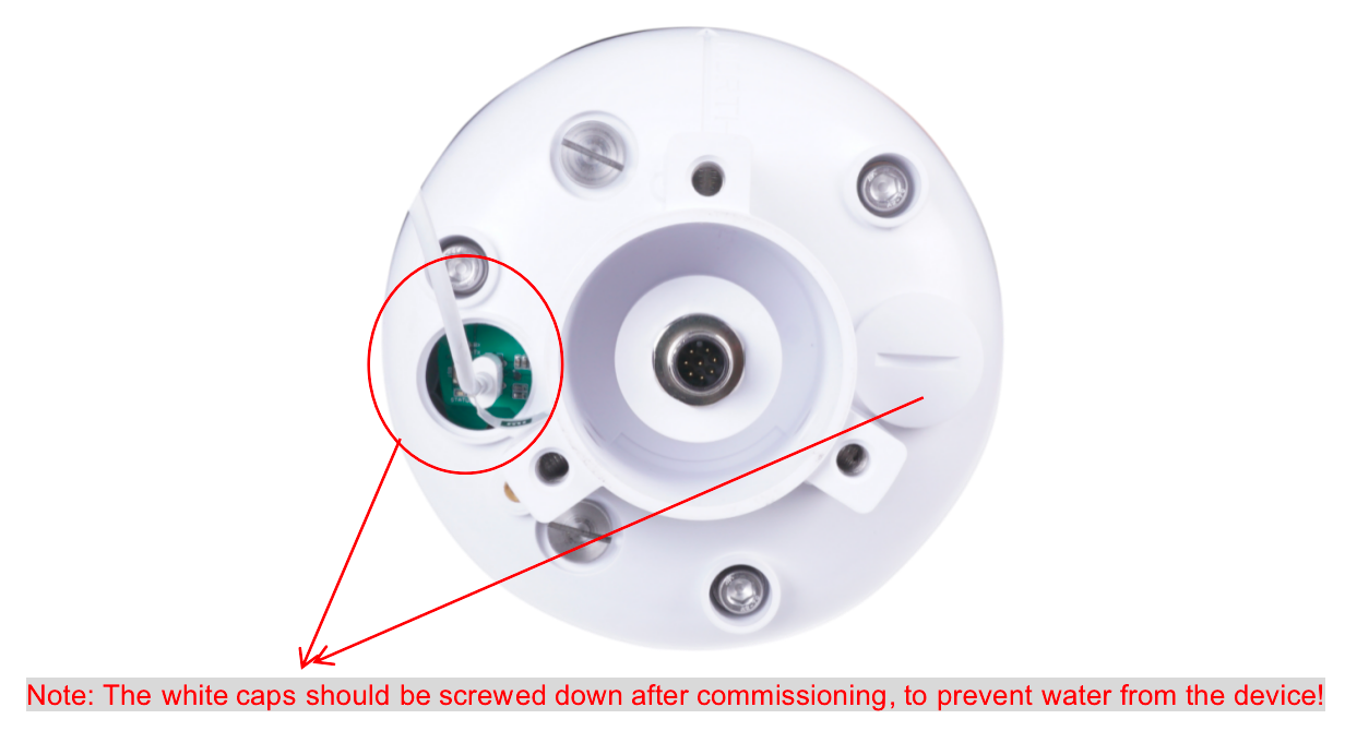
V2 Device Interface Layout
Connect with USB Cable
M12 Cable
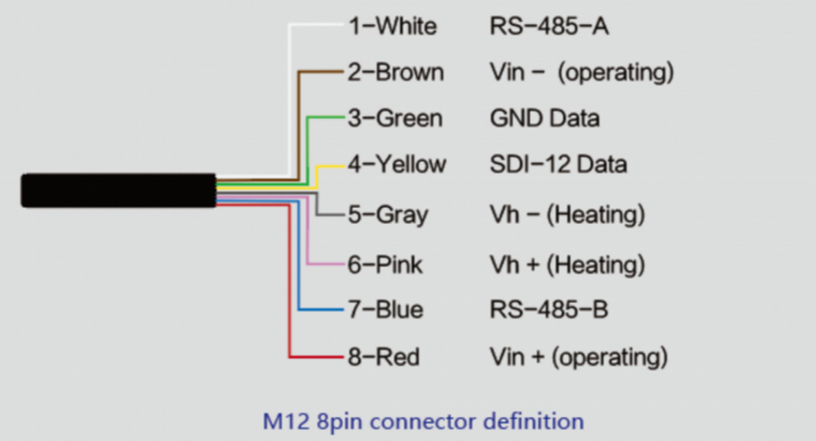
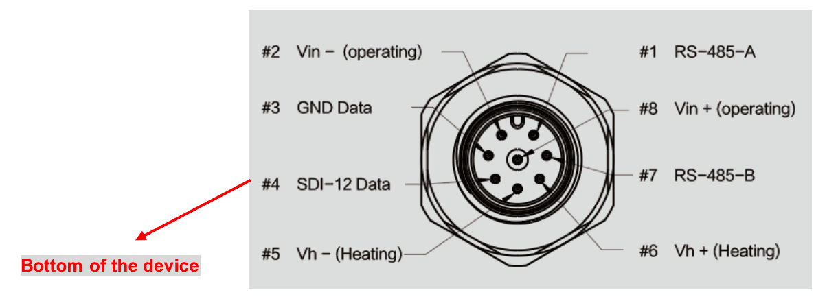
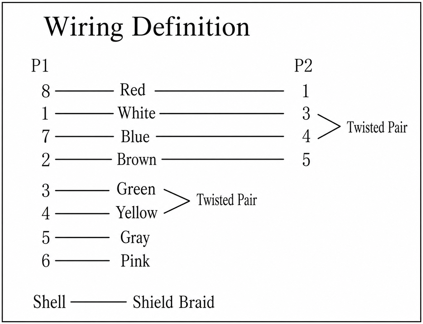
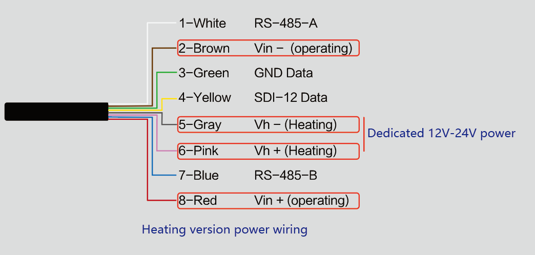
The device adopts an M12 8-pin connector, the different colored pins provide power and data communication (as shown in the above diagram).
When working with the RS-485, you can connect only 4 wires (not using a heating function), and the rest can be individually wrapped with tape to prevent short circuit
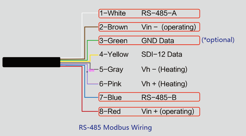
Below is the wiring schematic for the M12 connector for your reference.
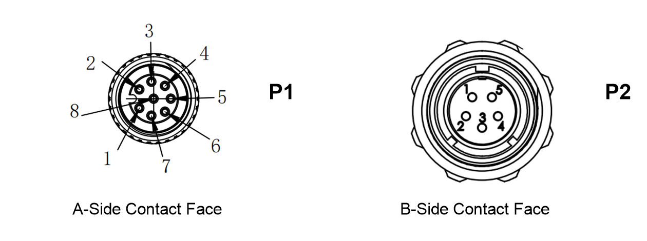
The image below is a wiring definition diagram.
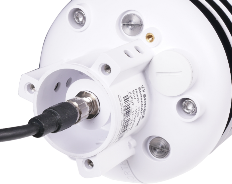
The holes of the cable and the pins of the device connector must be aligned when the cable is plugged in.
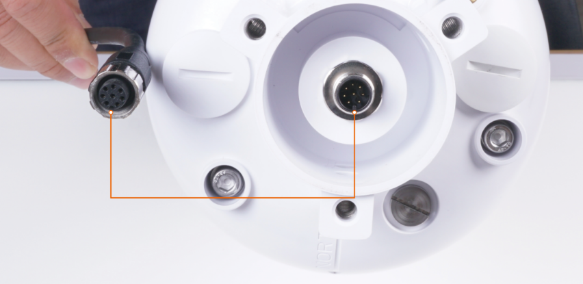
Plugin the cable and tighten it clockwise
Note: the cable is aimed at the bottom before inserting it into the bottom. Otherwise, the pins are skewed may cause the communication to be abnormal.
When using the device with a heating function, a separate 24V (24V@1A is recommended) power supply is required. Gray wire 5 is connected to the negative of the power supply, and pink wire 6 is connected to the positive pole of the power supply.
Install the device
There are two major installation methods, either mounted on a pole with a sleeve or a platform with a flange plate.
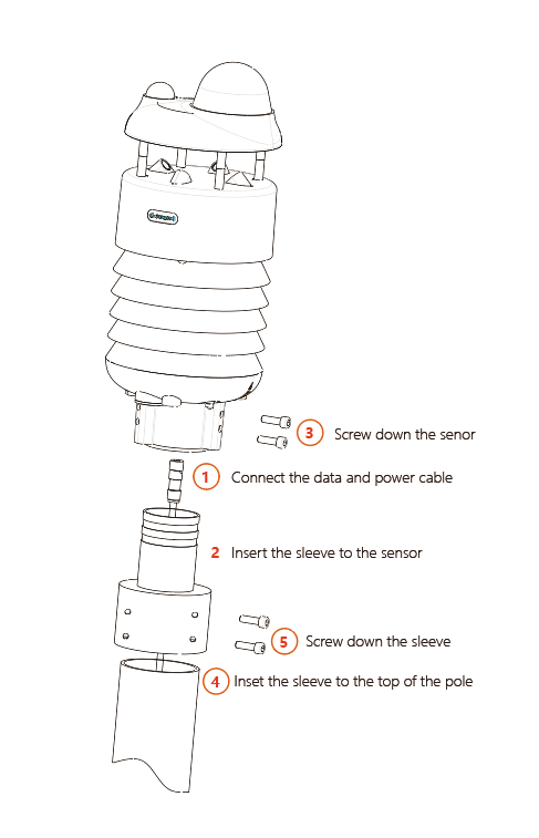
The size of the sleeve is shown below.
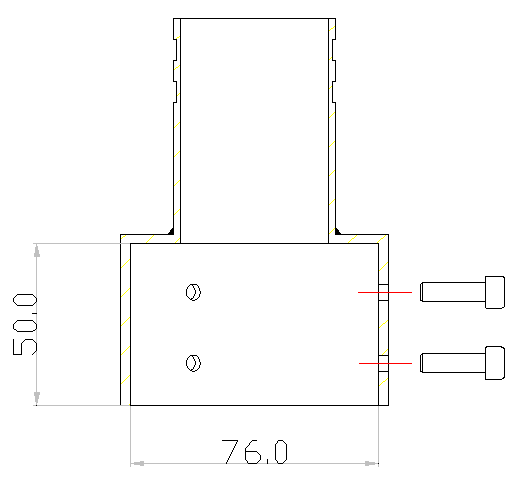
It is recommended that the diameter of the pole should be less than or equal to 75cm.
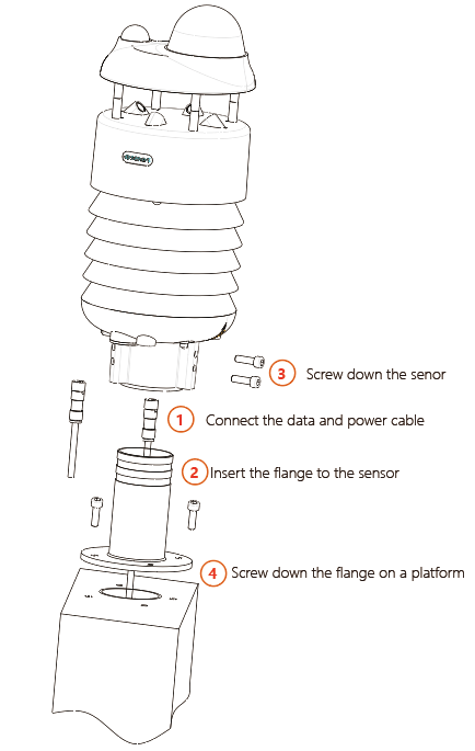
The dimension of the flange plate is shown below.
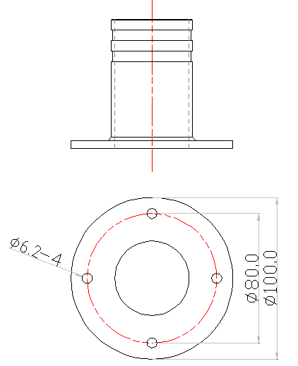
Note: To obtain the most accurate wind direction data possible, please ensure the physical north orientation during installation by aligning the arrow on the base directly toward true north. Otherwise, please enable the electronic compass during configuration.
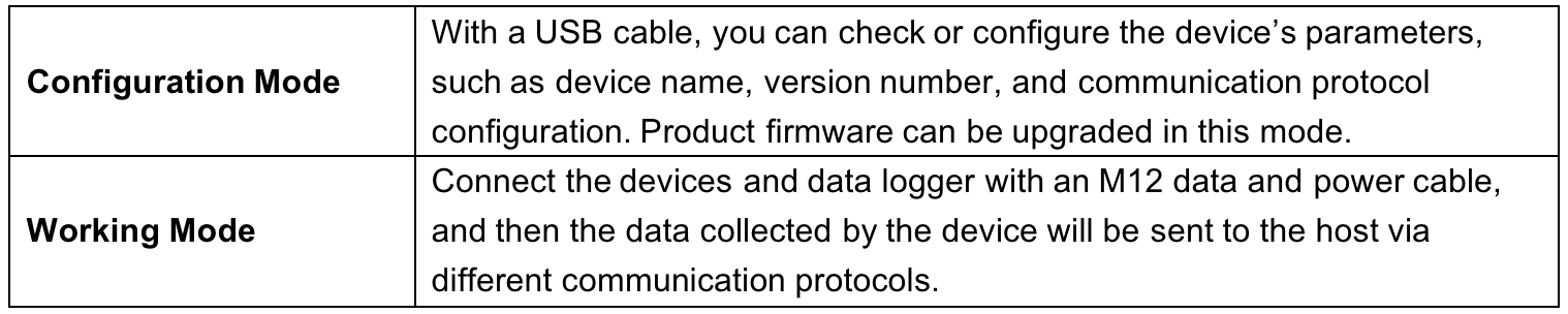
Device's Operating Mode
After installation, you can power on the device, configure it and collect data from the device.
The device has two operating modes, configuration mode, and working mode.
Configure the device via USB port
There is a waterproof round cover at the bottom of the device. Turn it counterclockwise to remove this cover, and you can see a USB Type-C connector and a configuration button.
Connect the device to your computer with a USB Type-C cable. The computer will automatically install the device driver. After the driver is successfully installed, you can see a serial port in the device's manager.
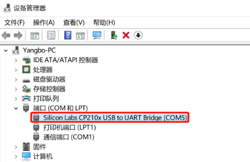
If the driver is not installed automatically, click this link to manually download and install the driver.(The version is CP210x Windows Drivers)

There are two methods to configure the device:
-
SenseCAP ONE Configuration Tool
-
Serial debug tool
SenseCAP ONE Configuration Tool
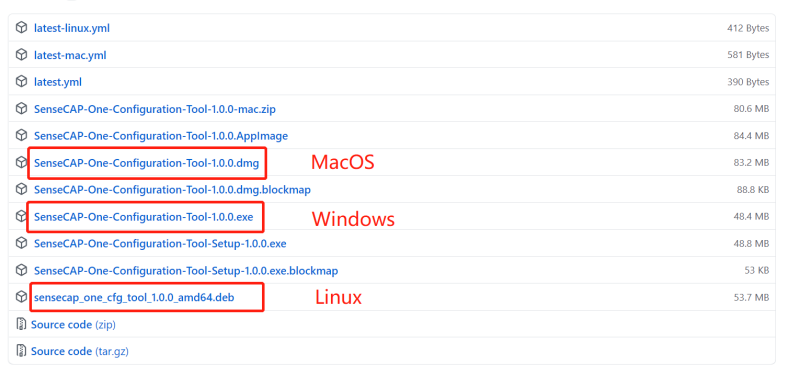
SenseCAP ONE Configuration Tool offers a graphical interface for you to configure the device. And you can download the tool from the GitHub link below:
<https://github.com/Seeed-Solution/SenseCAP-One-Configuration-Tool/releases>
Select the software for the respective operating system, Windows, macOS, or Linux based on your needs.
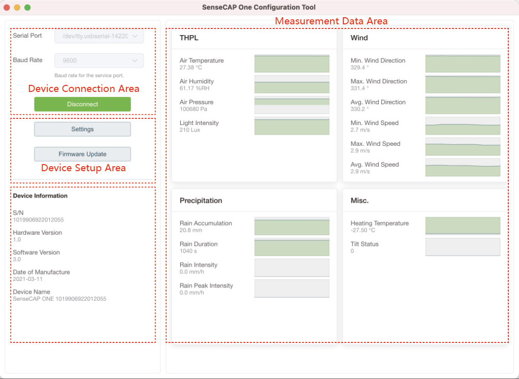
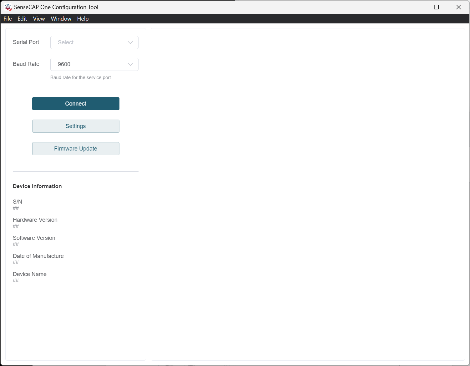
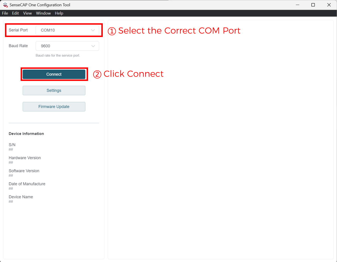
The next image shows the main interface of the SenseCAP ONE Configuration Tool.
-
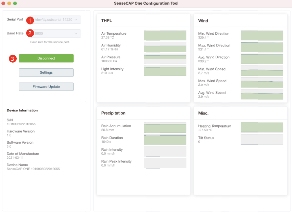
Open the software, click on the pull-down box at the serial port, and select the corresponding serial port of the device.
-
Set the Baud rate to 9600.
-
Click connect, if the connection is successful, the sensor data area on the right will show the corresponding measurements.
Click Settings to enter the device settings, and click"Read From Device" to obtain information about the device.

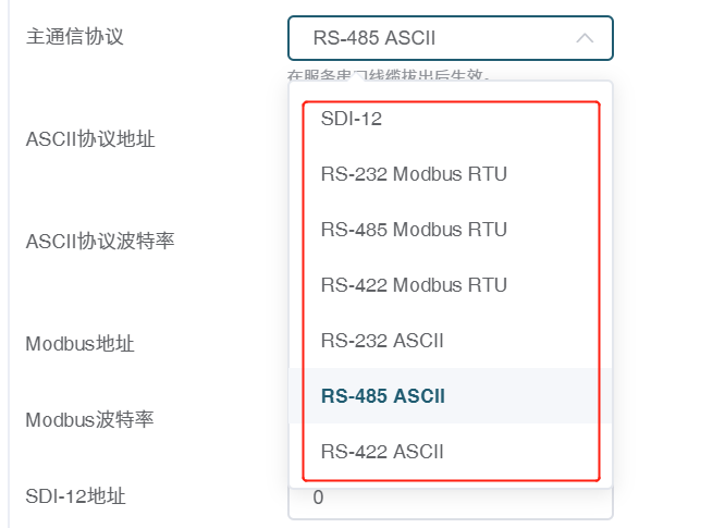
- Select the communication protocol. In the example here we choose the RS-485 Modbus RTU.
- Modify the Modbus address: write the address in the Modbus address, and then click "Write to Device".
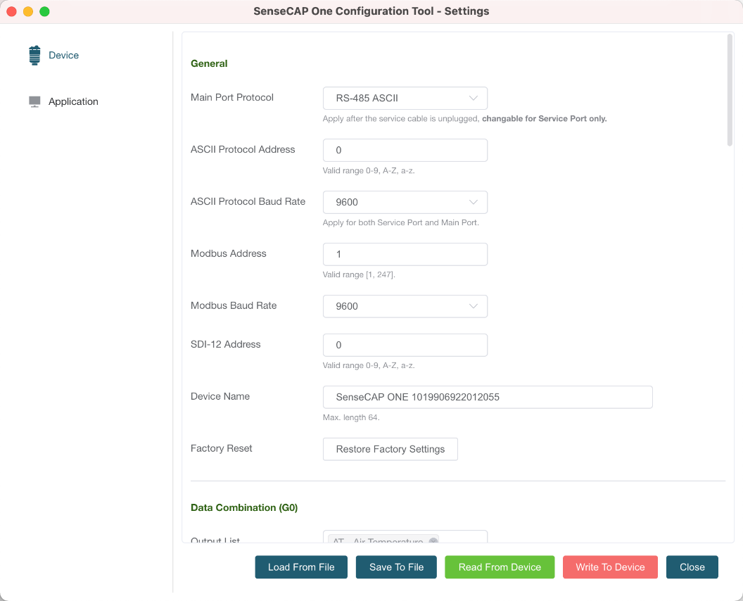
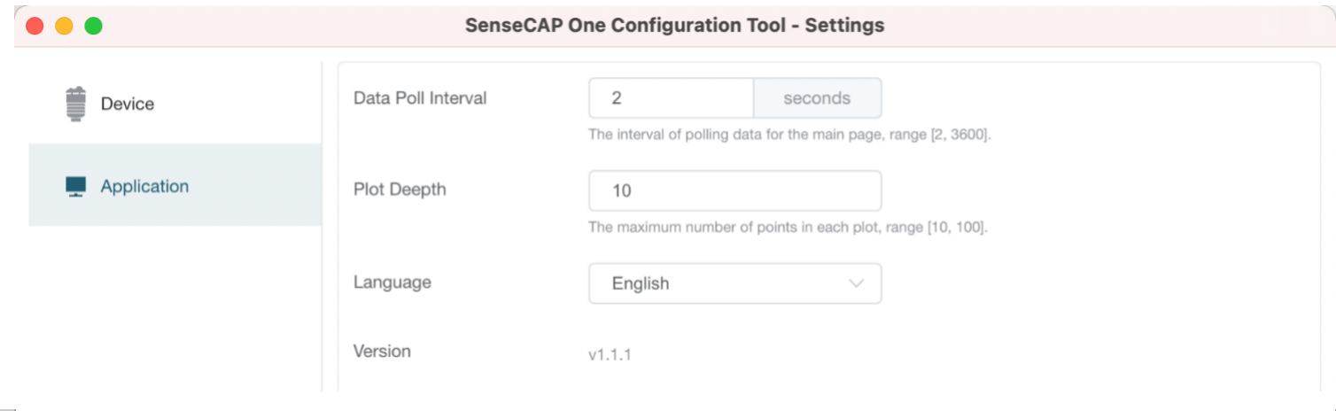
On the configuration page, you can modify the following: device name, data type, and data upload interval. After any modification, you will need to click "Write to Device" for the changes to take effect.
In application settings, you can set the cycle for the tool to read sensor data, with the minimum as 2S, and a dot range for the curve.
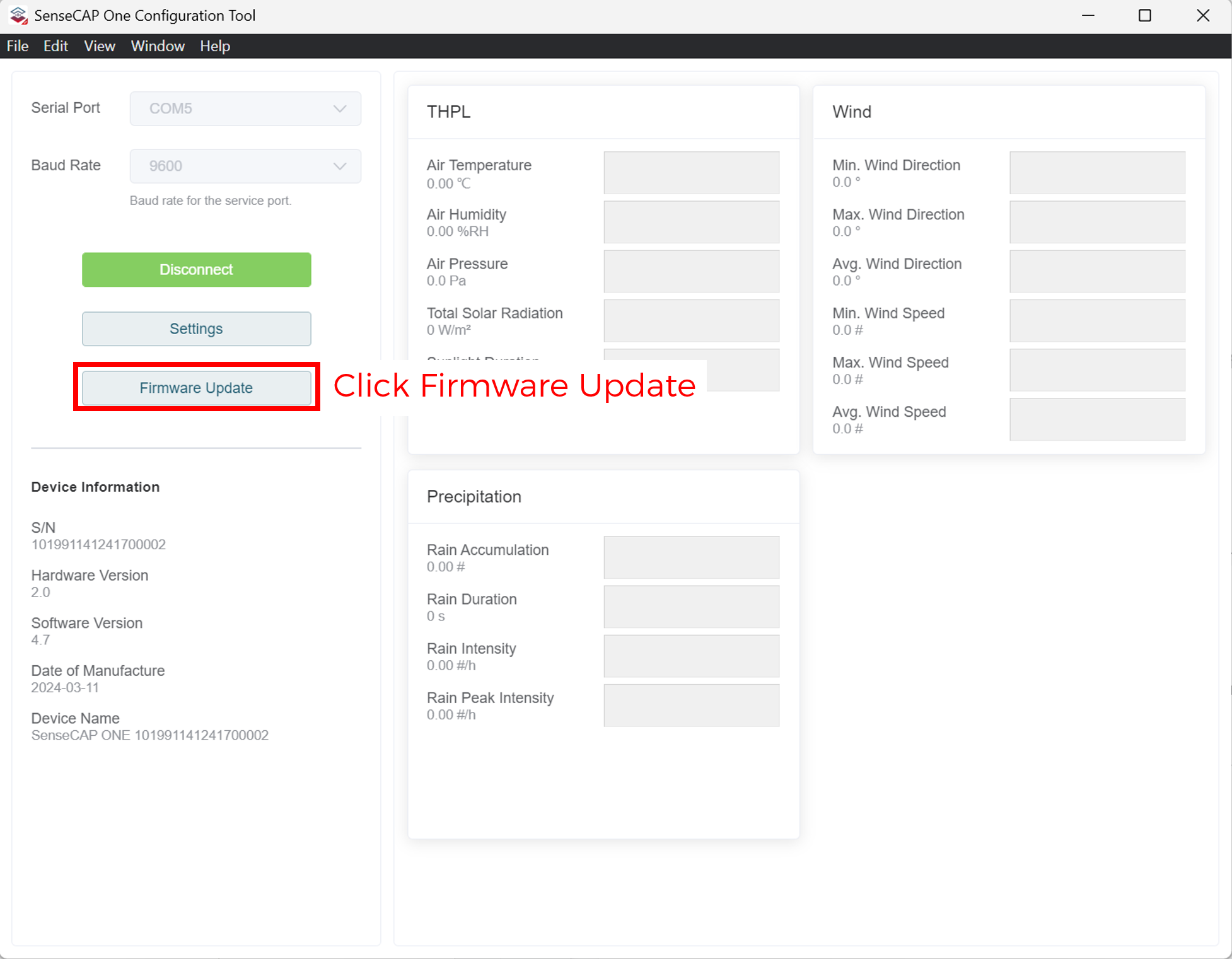
Click "Firmware Update" to update the device firmware. Please contact sales or technical support at ([email protected]) to get the firmware.
On the upgrade page, you will need to choose to update the mainboard firmware or the driver board firmware. Select the firmware file at your local repository, and click "Update Now". If there is an unexpected power break during the update process, the update won't be executed. You will need to go through the same process to update the firmware.
Firmware Upgrade
- Open
SenseCAP One Configuration Tool
-
Connect the device to your computer via the Type-C cable
-
Open the software, select the correct
COMport for the device, and click"Connect"
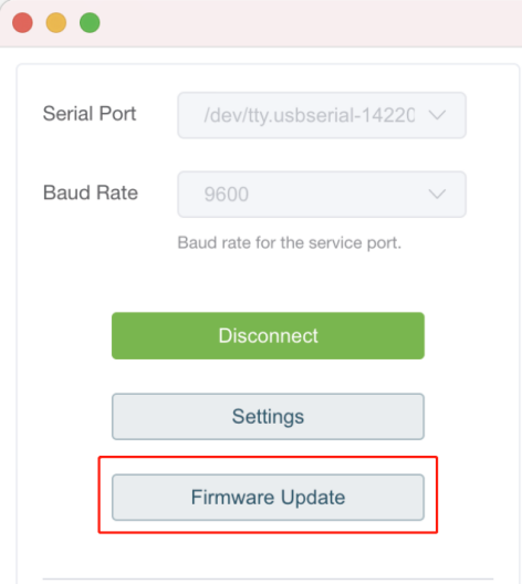
- After connecting, click
"Firmware Update"
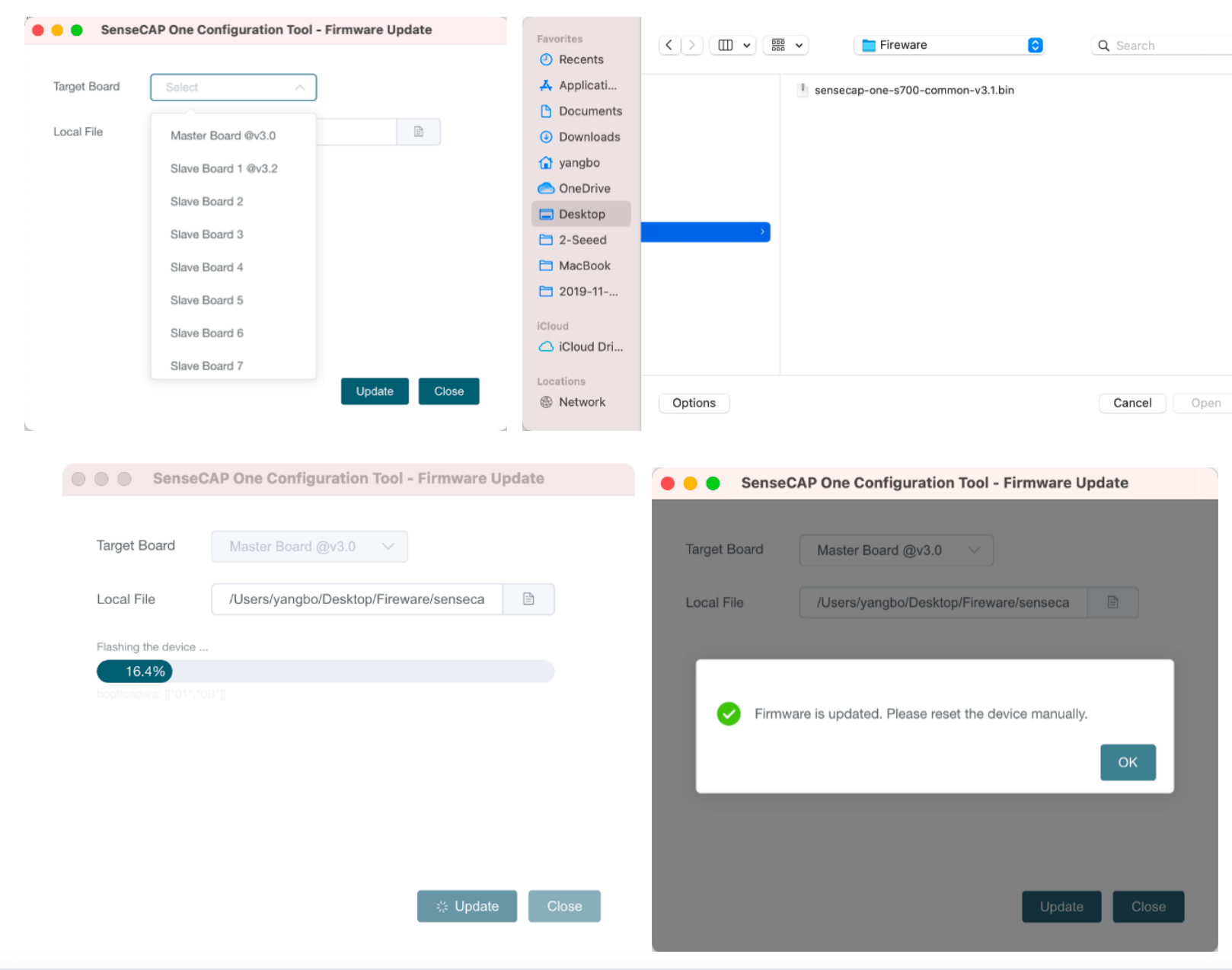
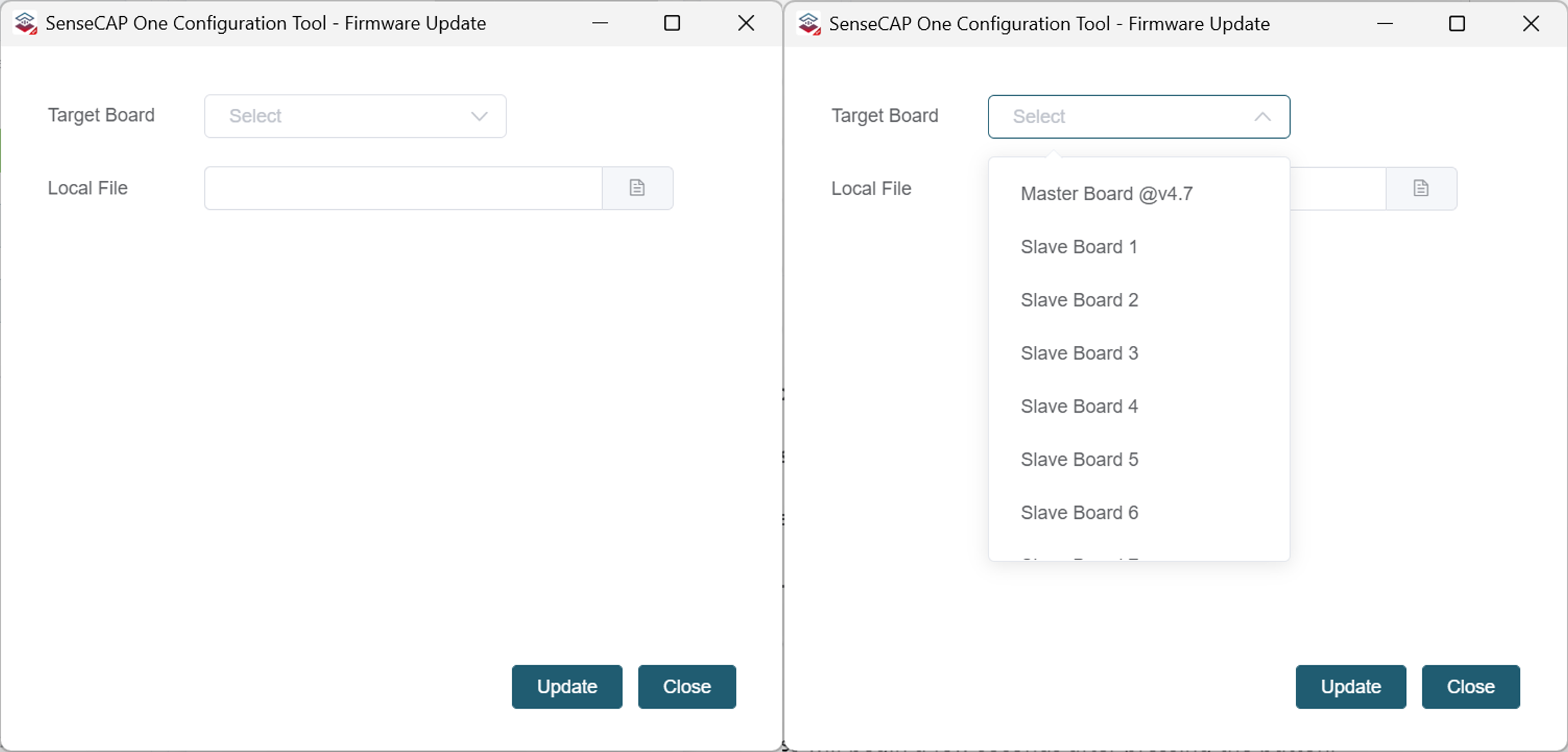
- Select the target board and the corresponding firmware file
- Select the
Master board
-
Click
"Local File"and browse to the firmware folder -
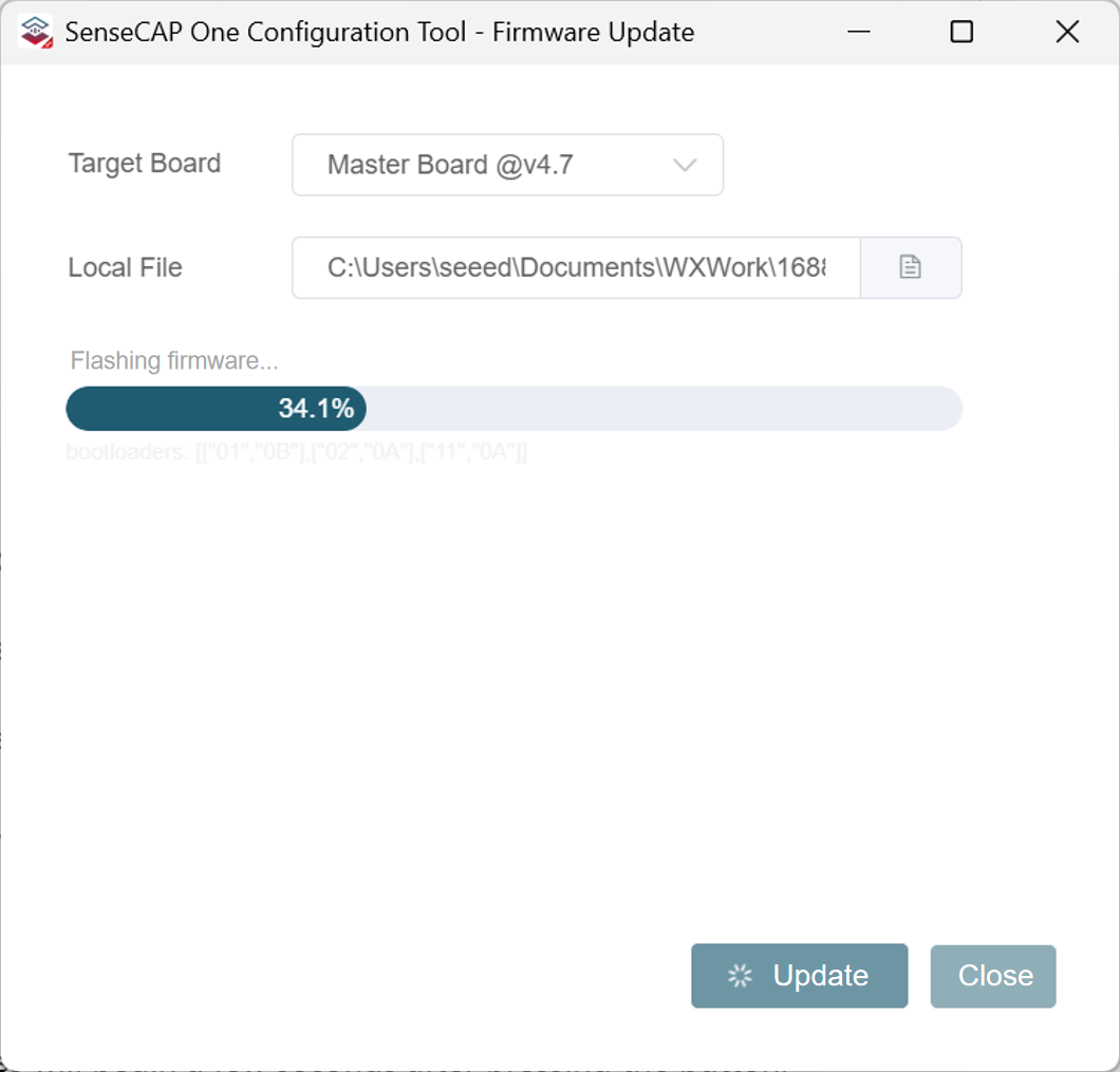
Click
"Update"
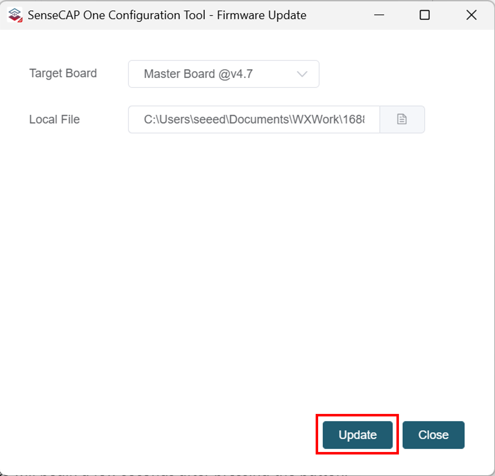
- Press the Reset button on the device (located next to the Type-C port) after clicking
"Update".
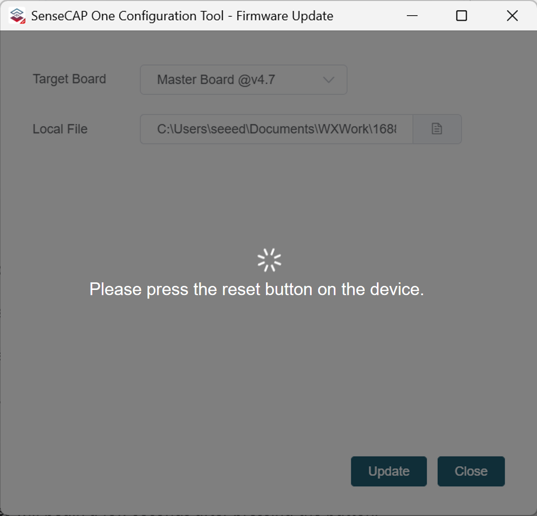
The update process will begin a few seconds after pressing the button.
- Once the update is complete, press the Reset button again, then click
"OK"on the screen.

-
Repeat the above steps to flash another firmware onto
Slave Board 1. -
Close the Firmware Update window after completion, Click
"Disconnect".
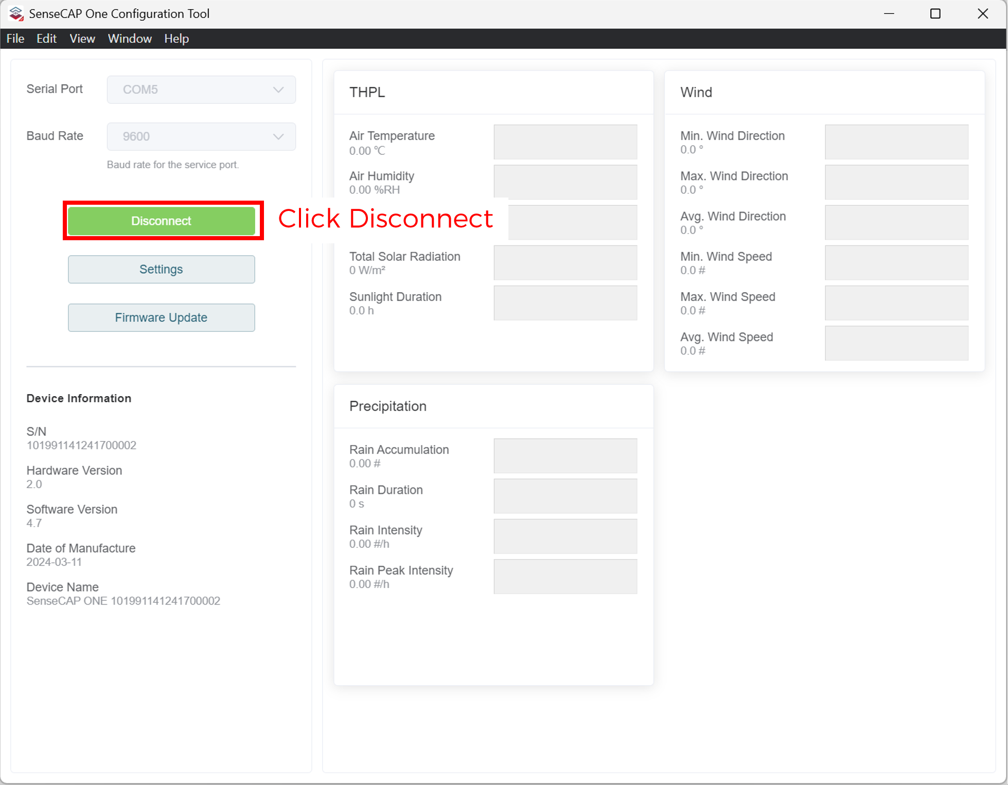
This completes all the firmware upgrade steps for the weather station.
Serial debug tool
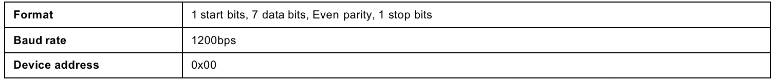
The communication settings are as follows:

-
In the Serial Debug Assistant, select the corresponding COM port.
-
Check the "click Enter to start a new line" check box.
-
Set the baud rate to 9,600.
-
Send in the send area.
-
If you receive the corresponding 0XA message in the serial receive window, the configuration is successful. If not, please check the COM port and the baud rate.
Please check the detailed ASIIC command in the next chapter.
Communication Protocols
The device supports the following communication protocols:
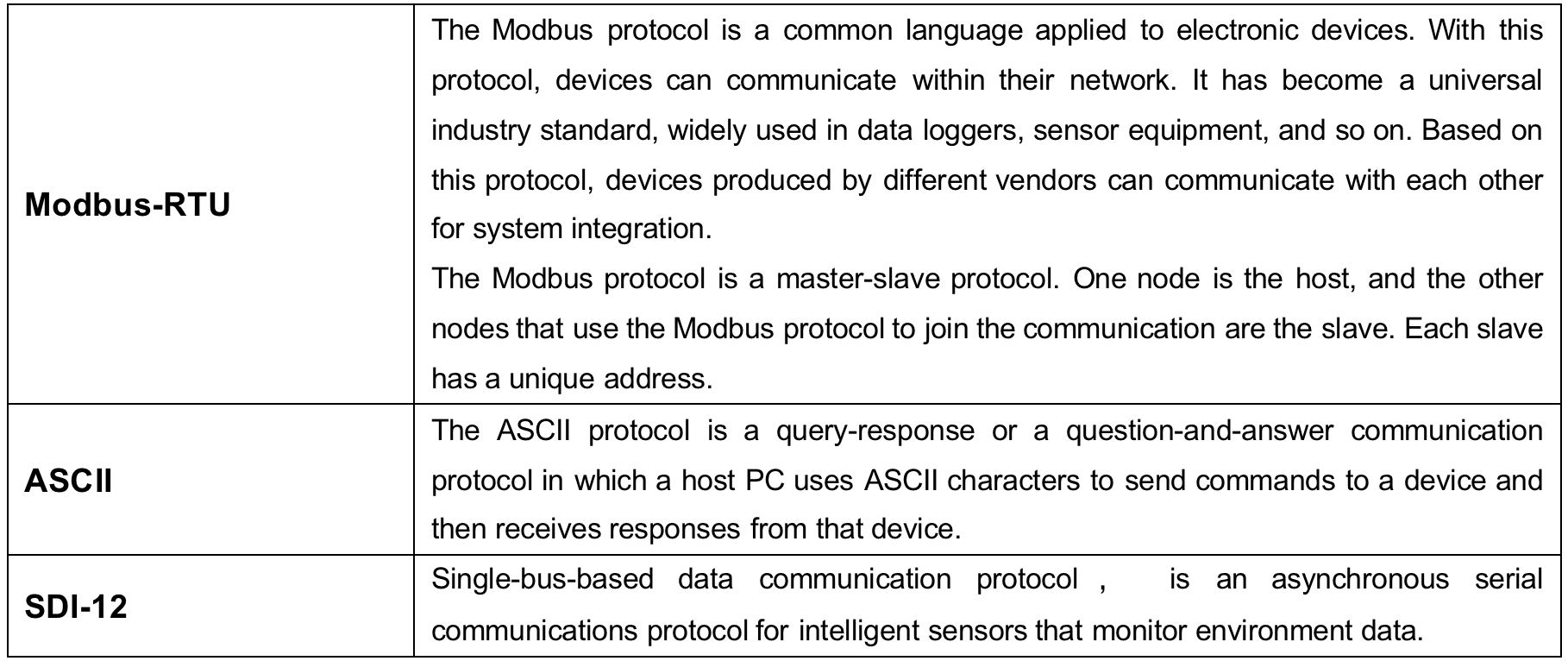
Modbus-RTU Protocol
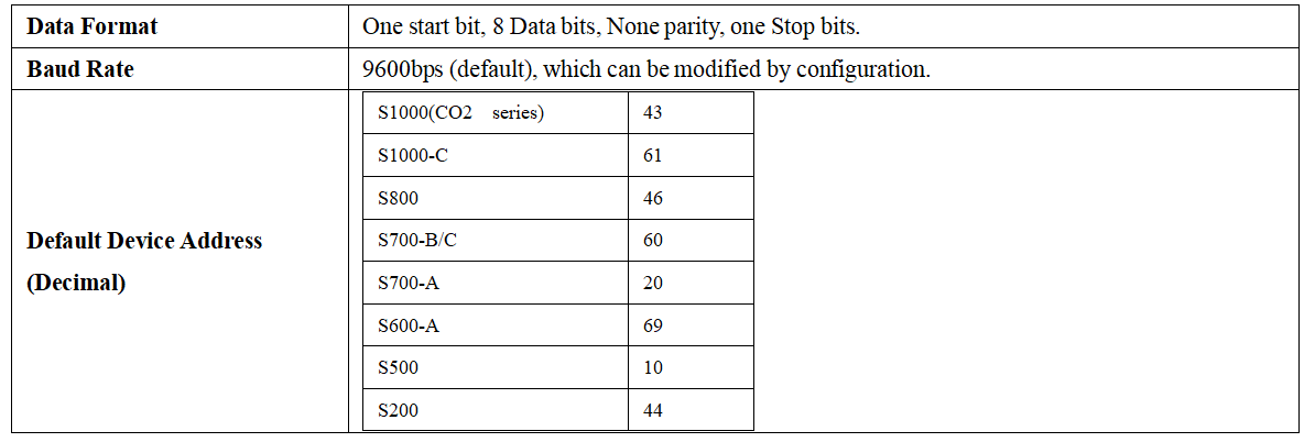
Protocol communication parameters
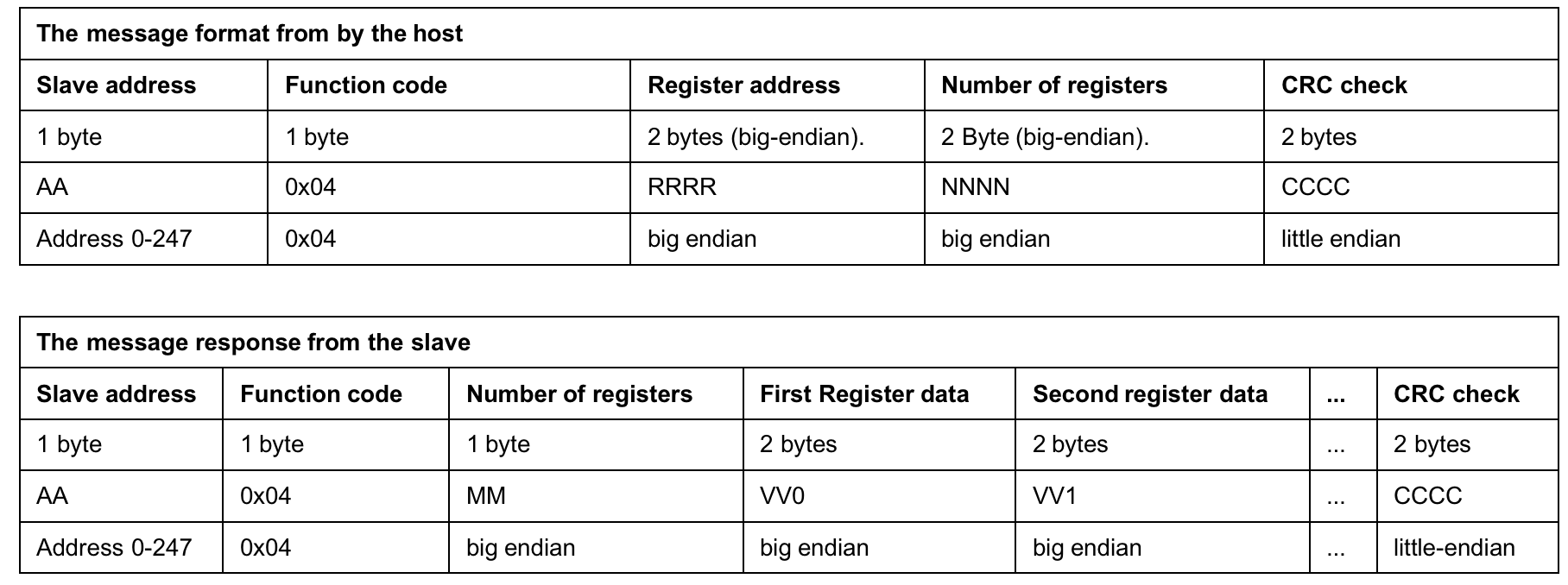
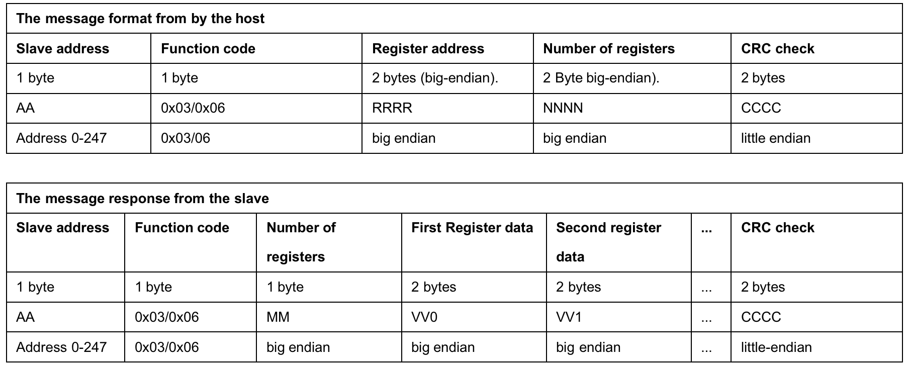
Modbus-RTU Protocol Message Format
Sensor data is stored in the Input Register and is read-only.
The device address and the communication baud rate of RS-485 are stored in the Holding Register and can be modified.
Each register is 16 bits and takes up 2 bytes.
Read the message from the input register.
Read and write the holding register.
Register Address Definition
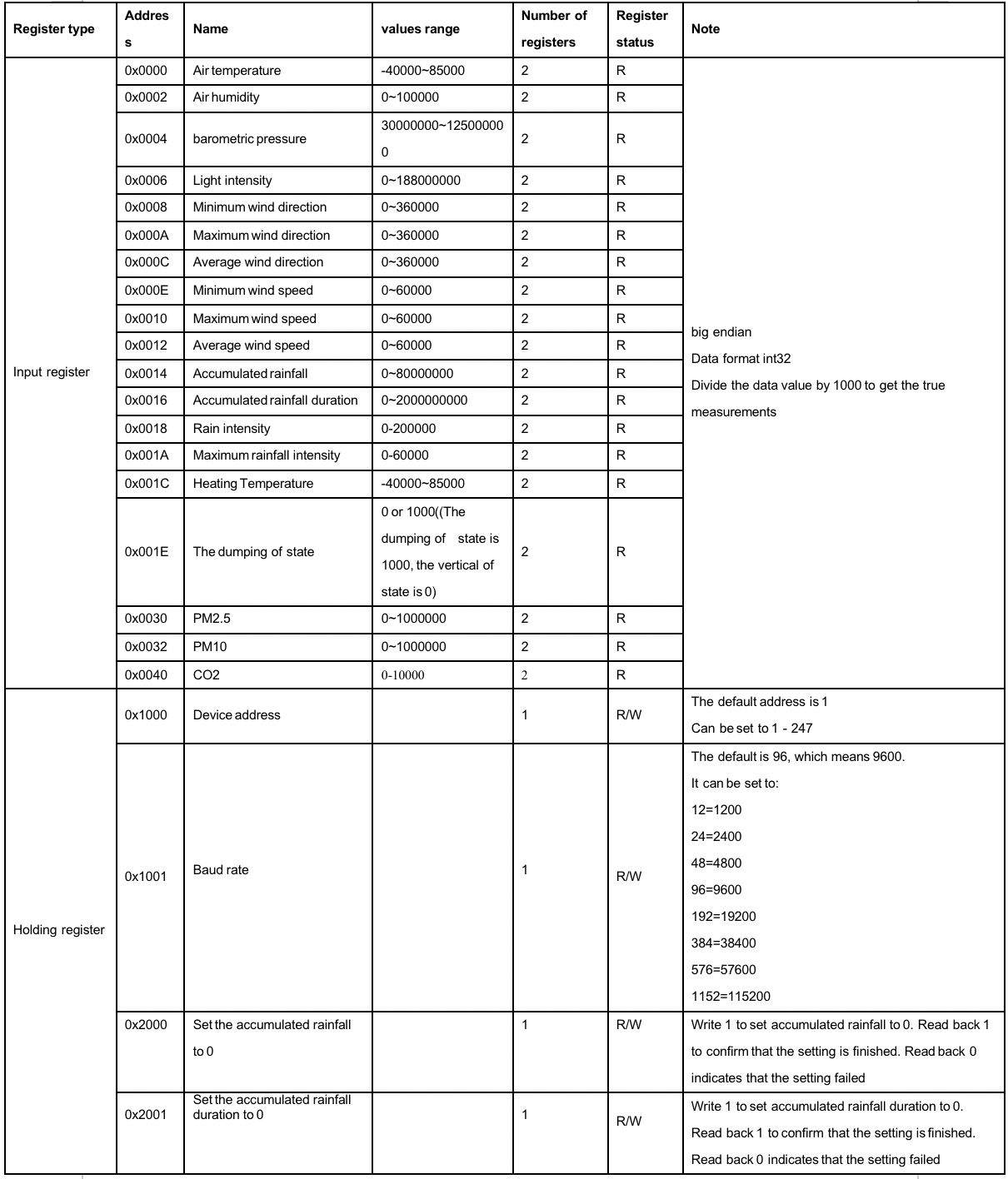
Modbus-RTU Read
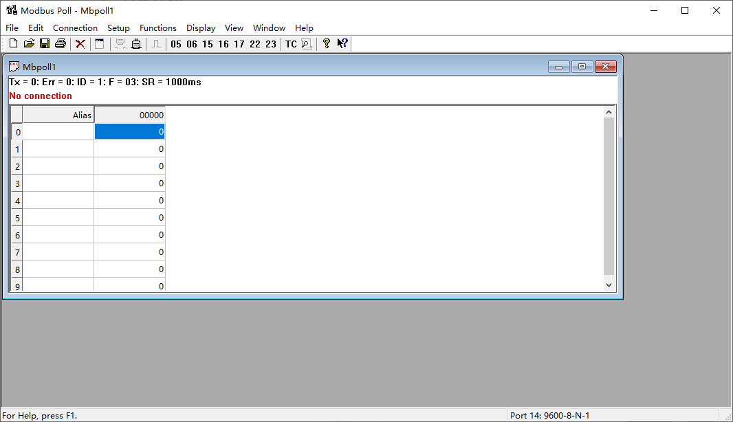
Here is an example of the Modbus Poll tool
(download from <https://www.modbustools.com/download.html>).
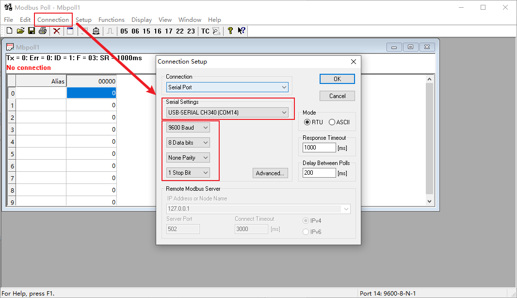
Configuration connection parameters: Baud rate 9600bps, 8 Data bits, None Parity, 1 Stop bits.
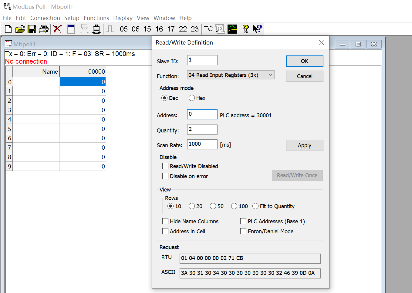
Read the air temperature register 0x0000 to 0x0001, click Setup, and select Read/Write Definition
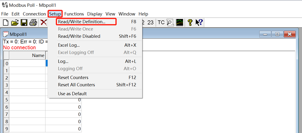
Set the default slave ID(5-in-1 is 10,7-in-1 is 20,9-in-1 is 38), function code 04, starting address 0, quantity (5-in-1 is 6,7-in-1 is 28,9-in-1 is 32);
Now the computer reads the sensor data every 1 second, and the measurement (line 0 and line 1) is shown below picture, after dividing the measurement by 1000, it is the true temperature value, 28300/1000 = 28.3 °C
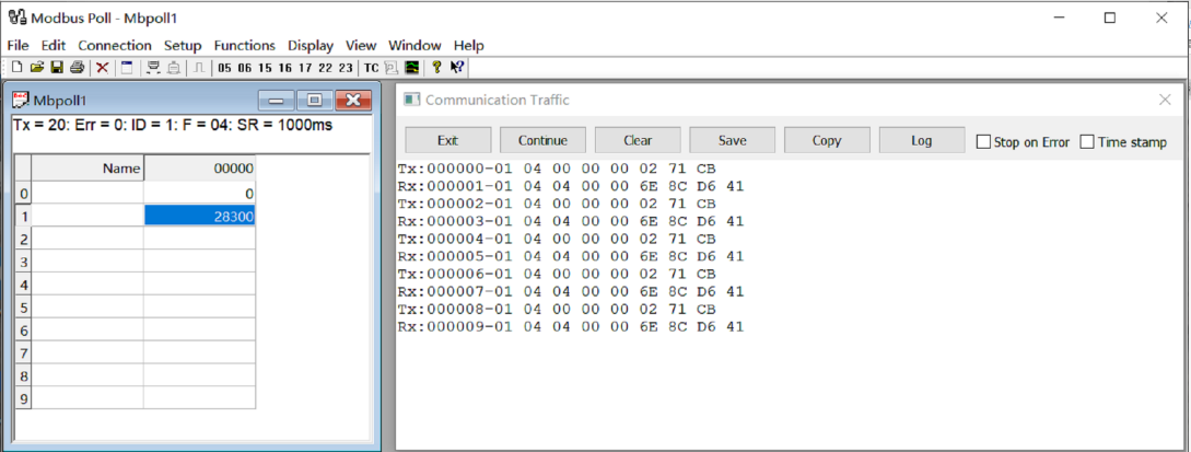
On the right, you can check the raw sent and received data packages.
When the temperature is positive:
-
Host sends 01 04 00 00 00 02 71 CB
-
Slave responses 01 04 04 00 00 6E 8C D6 41
-
Return temperature data 0x00006E8C (Hex), converted to decimal = 28300, get the corresponding air temperature by dividing it through 1000, air temperature = 28300/1000 = 28.3 °C
When the temperature is negative
The temperature needs to be obtained through a complement calculation.
-
Host sends 01 04 00 00 00 02 71 CB
-
Slave responses 01 04 04 FF FF FC 18 D6 41
-
Returned temperature data FFFFFC18H (Hex complement).
-
The original code is - (FF FF FC 18-1 = FF FF FC 17) = 80 00 03 E8(Hex) = -1000 (Decimal).
-
Then the temperature measurement is -1000/1000 = -1°
S500 decode
Read register 0x0000~0x0005.
Send command:0A 04 00 00 00 06 71 73(Check code);
Return:26 04 40 00 00 70 80(Temperature)00 00 95 10(Humidity) 06 07 94 40(Air pressure)99 09(Check code);Read register 0x0008~0x0013. Send commond:0A 04 00 08 00 0C 70 B6(Check code);
Return:0A 04 0C 00 00 00 00(Min wind direction)00 03 6E 84(Max wind direction)00 03 C8 C0(Avg wind direction)00 00 00 00(Min wind speed)00 00 04 BC(Max wind speed)00 00 02 10(Avg wind speed)BC 78(Check code)
S600 decode
Read register 0x0000~0x0013
Send command: 45 03 00 00 00 13 0B 43
Return: 45 04 40 00 00 70 80(Temperature) 00 00 95 10(Humidity) 06 07 94 40(Air pressure) 00 00 00 00(Light) 00 00 00 00(Min wind direction) 00 00 00 00(Max wind speed) 00 00 00 00(Avg wind direction) 00 00 00 00 (Min wind speed) 00 00 00 00(Max wind speed) 00 00 00 00(Avg wind speed)77FD(Check code)
S700 decode
Read register 0x0000-0x001F & 0x0030-0x0033.
Send command: 14 04 00 00 00 20 F3 06
Return: 14 04 40 00 00 70 80(Temperature) 00 00 95 10(Humidity) 06 07 94 40(Air pressure) 00 00 00 00(Light) 00 00 00 00(Min wind direction) 00 00 00 00(Max wind direction) 00 00 00 00(Avg wind direction) 00 00 00 00 (Min wind speed)00 00 00 00(Max wind speed) 00 00 00 00(Avg wind speed) 00 00 00 00(Accumulated rainfall) 00 00 00 00(Accumulated rainfall duration) 00 00 00 00(Rain intensity) 00 00 00 00(Maximum rainfall intensity) 00 00 6A 7C(Heating Temperature) 00 00 00 00(The dumping of state) 99 09(Check code)
S900 decode
Read register 0x0000-0x001F & 0x0030-0x0033.
Send command: 26 04 00 00 00 20 F7 05
Return: 26 04 40 00 00 70 80 (Temperature) 00 00 95 10(Humidity) 06 07 94 40(Air pressure) 00 00 00 00(Light) 00 00 00 00(Min wind direction) 00 00 00 00(Max wind direction) 00 00 00 00(Avg wind direction) 00 00 00 00 (Min wind speed) 00 00 00 00(Max wind speed) 00 00 00 00(Avg wind speed) 00 00 00 00(Accumulated rainfall) 00 00 00 00(Accumulated rainfall duration) 00 00 00 00(Rain intensity) 00 00 00 00(Maximum rainfall intensity)00 00 6A 7C(Heating Temperature) 00 00 00 00(The dumping of state) 99 09(Check code)
PM2.5 and PM10 need to be read separately:
Send command: 26 04 00 30 00 04 F7 11
Return: 26 04 08 00 00 90 88(PM2.5) 00 00 A4 10(PM10) 13 FA(Check code)
S1000 decode
Read register 0x0000-0x001F and 0x0030-0x0033.
Send command: 2B 04 00 00 00 20 F6 18
Return: 2B 04 40 00 00 70 80 (Temperature) 00 00 95 10(Humidity) 06 07 94 40(Air pressure) 00 00 00 00(Light) 00 00 00 00(Min wind direction) 00 00 00 00(Max wind direction) 00 00 00 00(Avg wind direction) 00 00 00 00 (Min wind speed) 00 00 00 00(Max wind speed) 00 00 00 00(Avg wind speed) 00 00 00 00(Accumulated rainfall) 00 00 00 00(Accumulated rainfall duration) 00 00 00 00(Rain intensity) 00 00 00 00(Maximum rainfall intensity)00 00 6A 7C(Heating Temperature) 00 00 00 00(The dumping of state) 99 09(Check code)
PM2.5, PM10, and CO2 need to be read separately:
Send command: 2B 04 00 30 00 04 F6 0C
Return: 2B 04 08 00 00 90 88(PM2.5) 00 00 A4 10(PM10) 13 FA(Check code)
Read register 0x0040~0x0041.
Send command:2B 04 00 40 00 02 77 D5
Return:2B 04 04 00 0C EC 98 (CO2) FD 2F (Check code);
Noise sensor
The noise sensor is used as an independent RS485 sensor, which is parallel with other measuring units on the same RS-485 bus, so it needs to be read and configured separately.
Specification:
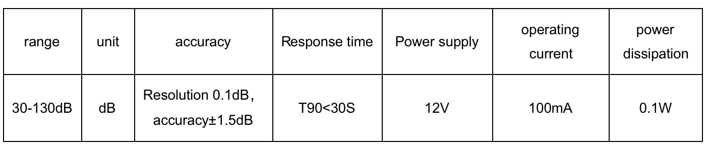
Data reading protocol and configuration:
The communication protocol adopts the standard RS485 Modbus-RTU protocol and the protocol communication parameters are as follows:

Querying the data of the noise sensor (address: 40, 0x28) :

If it is succeeded to query, the following information is returned:

Real DB = register value /100
The noise register value is 0x128E=4750, and the value is =4750/100=47.5dB
ASCII Protocol
Command definition
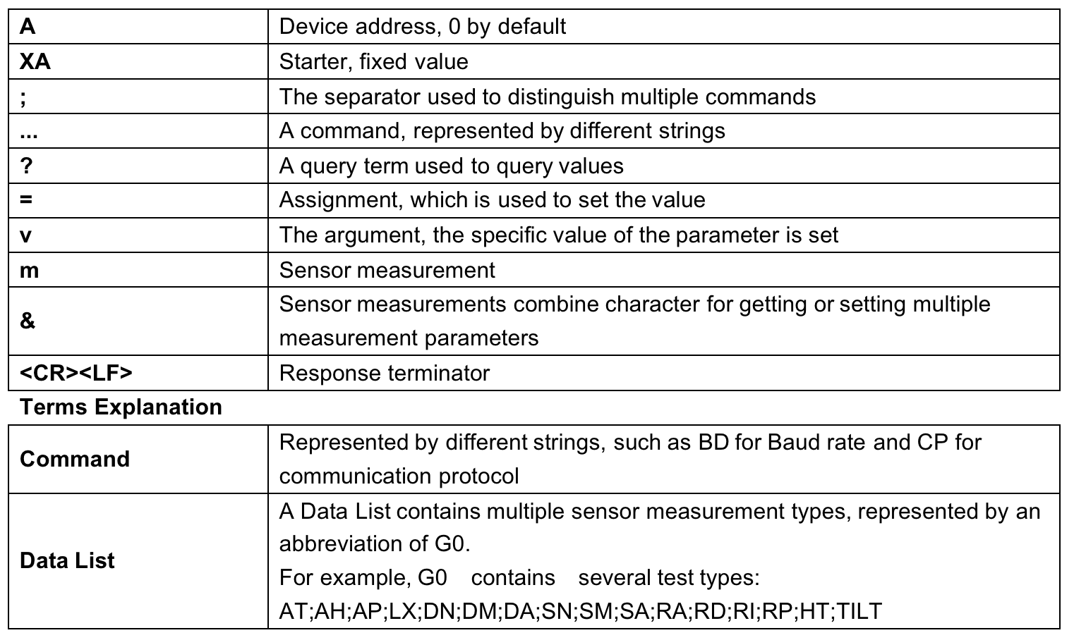
Query Command Format
Commands come in two formats:
1. A command without = refers to the basic query method.
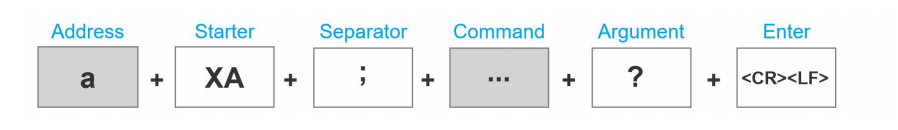
Example: ?<CR><LF> indicates query the device's address
2. A command with = refers to a query with an argument
Example: 0XA;BD=?<CR><LF> indicates query the device's baud rate
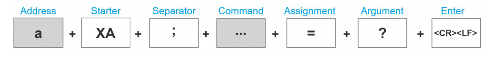
Setting Command Format
Set a specified parameter, such as setting a baud rate.

Example: 0XA;BD=96<CR><LF> indicates query the device's baud rate
Command List
Please refer to: SenseCAP ONE/SenseCAP ONE V3 Compact Weather Station User Guide
SDI-12
SDI-12 communication adopts three wires, two of which are sensor power supply wires and the other is SDI-12 signal wire.
Each sensor on the SDI-12 bus has a unique address, which can be set to '0', '1' ~ '9', 'A' ~ 'Z', 'A' ~ 'Z'. The SDI-12 address of the SenseCAP ONE defaults to '0'. The instructions supported by this sensor are shown in the next chapter, where each instruction conforms to the SDI-12 v1.4.
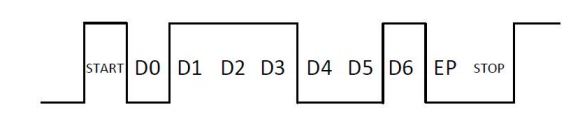
The sensor is powered by a DC power supply of 3.6~16V. After the sensor is powered on, it will go into sleep mode immediately and wait for the data acquisition equipment to give instructions. SDI-12 uses a baud rate of 9600bps, 1 start bit (high level), 7 data bits (high 0 and low 1, anti-logic), 1 even parity bit, and 1 stop bit.
The sequence of each byte sent is shown in the following figure:
SDI-12 command and response
Please refer to SenseCAP ONE/SenseCAP ONE V3 Compact Weather Station User Guide
SDI-12 Read
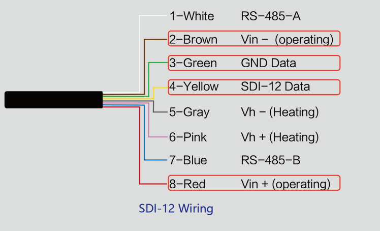
Wiring the SDI-12
Use USB to SDI-12 debugger to communicate with the device
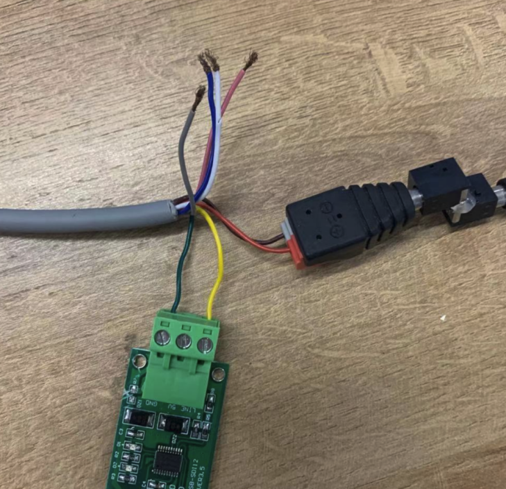
The communication settings:
Connect the green wire (GND Data) and yellow wire (SDI-12 Data) to the USB to SDI-12 debugger.
And connect the red wire (Vin+ power positive) and brown wire (Vin-power ground) to the 12V power supply.
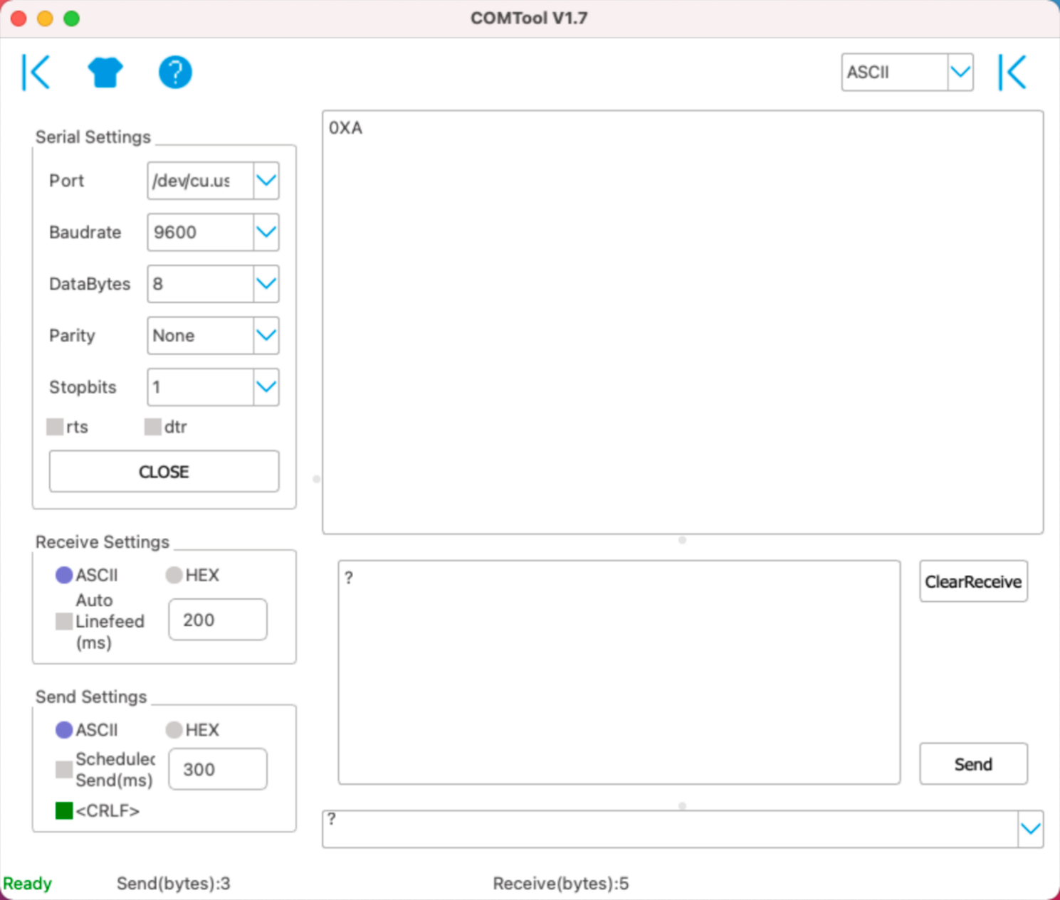
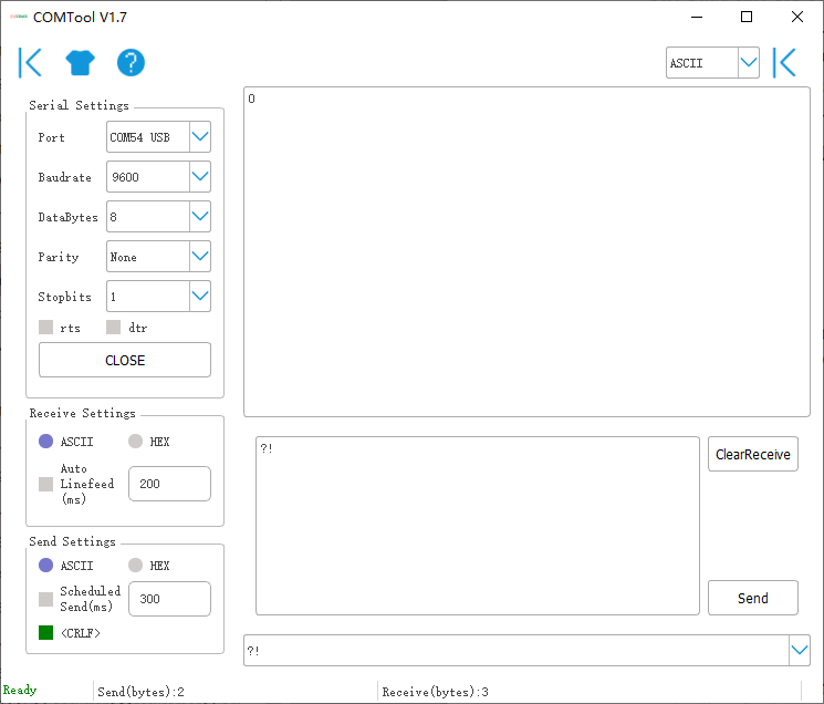
Download the serial port debugging assistant: <https://github.com/Neutree/COMTool>, and then open the serial port debugging tool.
-
Choose the correct port number
-
Set the baud rate to the baud rate of the USB to SDI-12 debugger (note that it is not the baud rate of the SDI-12 protocol)
-
Check the "CRLF"
-
Click to open the serial port.
-
Send the query device address command "?!", if you can see the response "0", it means the connection is OK.
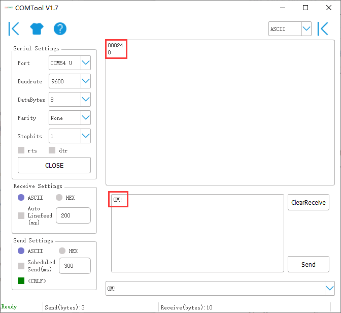
Start Measurement
Read air temperature, air humidity, barometric pressure, light intensity
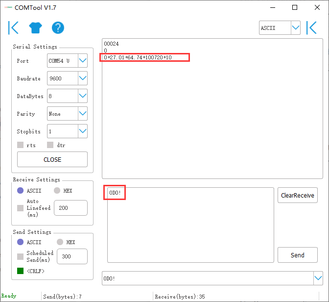
Send the "start measurement command 0M!", the sensor first responds with "00024", which means that the "0M!" command takes 2 seconds to measure and returns 4 measured values. After 2 seconds, the sensor responds with its own address "0", indicating that the measurement has been completed.
Then send " Read measurement value command 0D0!" to get the 4 measured values of this measurement, which are air temperature +27.01℃, air humidity 64.74%, barometric pressure 100720Pa, and light intensity 10Lux.
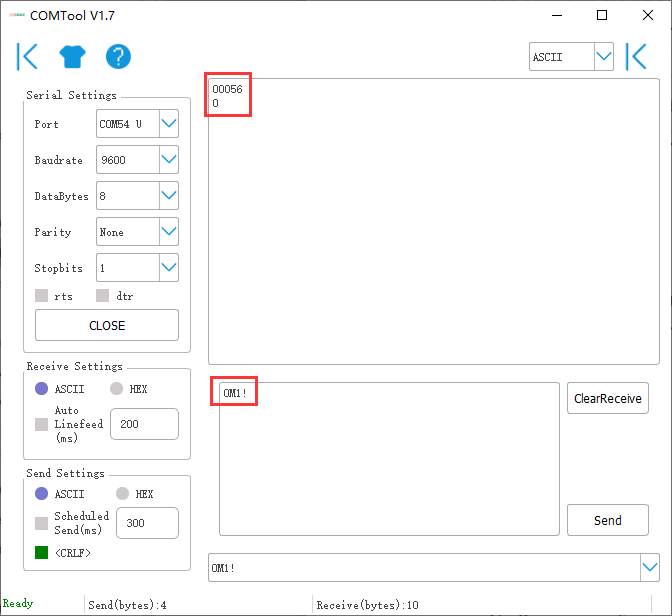
Use extended measurement command 0M1! to read minimum wind direction, maximum wind direction, average wind direction, minimum wind speed, maximum wind speed, and average wind speed. The device responds with "00056", which means that the "0M1!" command takes 5 seconds to measure and returns 6 measured values. After 5 seconds, the device responds with its own address "0", indicating that the measurement has been completed.
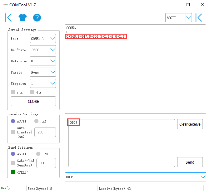
Then send "Read measurement value command 0D0!" to get the 6 measured values of this measurement, which are minimum wind direction 345.9 degrees, maximum wind direction 347.5 degrees, average wind direction 346.3 degrees, minimum wind speed 2.8m/s, and maximum wind speed 2.8m/s, average wind speed 2.8m/s.
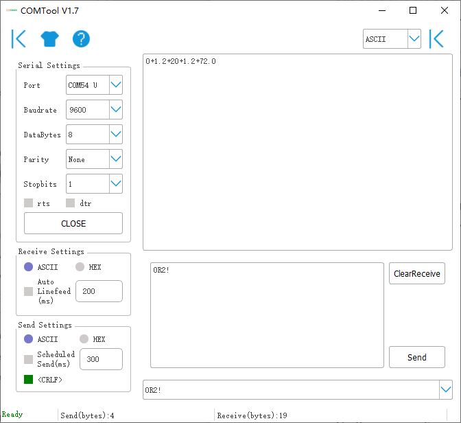
Then send "continuous measurement command 0R2! the device returns 4 measured values: cumulative rainfall 1.2mm, cumulative rainfall duration 20 seconds, rainfall intensity 1.2mm/h, maximum rainfall intensity 72.0mm/h.
Error code
Modbus error code

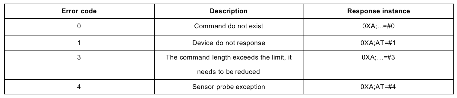
ASCII error code
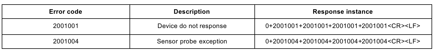
SDI-12 error code
Resource
SenseCAP ONE/SenseCAP ONE V3 Compact Weather Station User Guide
FAQ
How is the average wind speed and direction calculated?
The default average time window is 5s. Within this window, the device will collect wind speed and directiondatafive times and return an average value.