Grove 12 Channel Capacitive Touch Keypad (ATtiny1616)

The Grove 12 button Capacitive Touch Keypad is built around the ATtiny1616, an AVR® 8-bit processor running at up to 16 MHz. ATtiny1616 is a low-power, high-performance chip integrated QTouch® peripheral touch controller which supports capacitive touch interfaces with proximity sensing and driven shield. With this module, you can easily create an arduino password keypad or a DIY phone keypad.
We made this keypad into a 3x4 form, just like the layout of a mobile phone keyboard. The traditional keypad requires 3 vertical lines and 4 horizontal lines to scan, which will occupy 7 I/O pins of the microcontroller. With the help of ATtiny1616 and Grove connector, only RX and TX two pins are enough for Grove - 12-Channel Capacitive Touch Keypad. You can easily use this module with a microcontroller with a hardware UART interface, or you can use the software UART to read the button input with two normal I/O pins.
All in all, the Grove 12 button Capacitive Touch Keypad is an easy-to-use module that requires very little code, especially when you use it with Grove compatible mainboards, no soldering, just plug and play.
Features
- Low Power ATtiny1616 controller
- 3.3V / 5V compatible
- Capacitive touch, high sensitivity
- 12 button keypad
- 4 pin Grove UART connector
- On-board LED indicator
Applications
- Phone keypad
- Password access
- Extended input interface
Pinout
Specification
| Parameter | Value |
|---|---|
| Supply voltage | 3.3V / 5V |
| CPU | AVR® 8-bit CPU @ 16MHz |
| Sensor type | Capacitive Touch Keypad |
| Button Quantity | 12 |
| Operate temperature Range | -40°C to 105°C |
| Output Interface | UART |
| Firmware Download Interface | UPDI |
Platforms Supported
| Arduino | Raspberry Pi | |||
|---|---|---|---|---|
 |  |  |  |  |
Getting Started
Play With Arduino
Materials required
| Seeeduino V4.2 | Base Shield | Grove 12 button Capacitive Touch Keypad |
|---|---|---|
 |  |  |
| Get ONE Now | Get ONE Now | Get ONE Now |
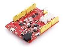
In addition, you can consider our new Seeeduino Lotus M0+, which is equivalent to the combination of Seeeduino V4.2 and Baseshield.
1 Please plug the USB cable gently, otherwise you may damage the port. Please use the USB cable with 4 wires inside, the 2 wires cable can't transfer data. If you are not sure about the wire you have, you can click here to buy
2 Each Grove module comes with a Grove cable when you buy. In case you lose the Grove cable, you can click here to buy.
Hardware Connection
- Step 1. Connect the Grove 12 Channel Capacitive Touch Keypad to the D2 port of the Base Shield.
If you are using a SAM board, then you should connect to the UART port. Please refer to table 1 for more detail
| Board | UART Type | Connect Port |
|---|---|---|
| AVR Board(like Seeeduino V4.2 | Soft UART | D2,D3 |
| SAM Board(like Seeeduino Lotus M0+ | Hardware UART | UART |
-
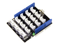
Step 2. Plug Grove - Base Shield into Seeeduino.
-
Step 3. Connect Seeeduino to PC via a USB cable.

Software
If this is the first time you work with Arduino, we strongly recommend you to see Getting Started with Arduino before the start.
-
Step 1. Download the 12_Channel_Keypad.ino from Github.
-
Step 2. Then open
12_Channel_Keypad.ino, or you can just copy the following code into a new Arduino sketch.
#include "SoftwareSerial.h"

#if defined(ARDUINO_ARCH_AVR)
#define SERIAL Serial
SoftwareSerial mySerial(2,3);
#define TRANS_SERIAL  mySerial
#elif defined(ARDUINO_ARCH_SAMD)
#define SERIAL SerialUSB
#define TRANS_SERIAL  Serial
#else

#endif


//RX=2,TX=3(D2) Software Serial Port

void setup() {
 TRANS_SERIAL.begin(9600);

    SERIAL.begin(9600);  // start serial for output
    SERIAL.println("Version:v1.0");
}

void loop() {
    printData();
}

/*
* data mapping:E1---1;E2---2;E3---3;E4---4;E5---5;E6---6;
*              E7---7;E8---8;E9---9;EA---*;EB---0;EC---#;
*/
void printData() {
    while(TRANS_SERIAL.available()) {
        uint8_t data = TRANS_SERIAL.read();
        switch(data) {
                case 0xE1 :
                    SERIAL.println("1");
                    break;
                case 0xE2 :
                    SERIAL.println("2");
                    break;
                case 0xE3 :
                    SERIAL.println("3");
                    break;
                case 0xE4 :
                    SERIAL.println("4");
                    break;
                case 0xE5 :
                    SERIAL.println("5");
                    break;
                case 0xE6 :
                    SERIAL.println("6");
                    break;
                case 0xE7 :
                    SERIAL.println("7");
                    break;
                case 0xE8 :
                    SERIAL.println("8");
                    break;
                case 0xE9 :
                    SERIAL.println("9");
                    break;
                case 0xEA :
                    SERIAL.println("*");
                    break;
                case 0xEB :
                    SERIAL.println("0");
                    break;
                case 0xEC :
                    SERIAL.println("#");
                    break;
                default:
                    break;
            }
    }

}
-
Step 3. Upload the demo. If you do not know how to upload the code, please check How to upload code.
-
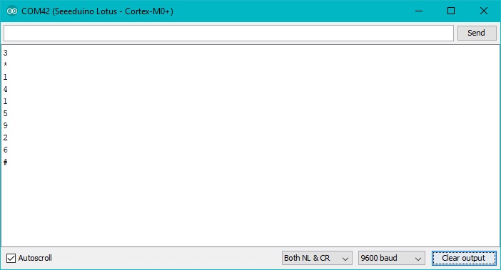
Step 4. Open the Serial Monitor of Arduino IDE by click Tool-> Serial Monitor. Or tap the
ctrl+shift+mkey at the same time. Set the baud rate to 9600.
Now, touch the keypad, then the monitor will output the corresponding key.

Play with Raspberry pi
Materials required
| Raspberry pi | Grove Base Hat for RasPi | Grove 12 button Capacitive Touch Keypad |
|---|---|---|
 |  |  |
| Get ONE Now | Get ONE Now | Get ONE Now |
-
Step 1. Plug the Grove Base Hat into Raspberry.
-
Step 2. Connect the Grove 12 button Capacitive Touch Keypad to UART port of the Base Hat.
-
Step 3. Power on the Raspberry Pi.

Software
If you are using Raspberry Pi with Raspberrypi OS >= Bullseye, you have to use this command line only with Python3.
UART Setting
Before start, we need to configure the Raspberry Pi UART.
- Step 1. Enable Raspberry Pi3 UART0.
sudo nano /boot/config.txt
Then add the content dtoverlay=pi3-disable-bt to the end of the config.txt
Tap ctrl+x to quit nano, and tap y to save the modification.
- Step 2. Disable the system serivce to use the UART0.
sudo systemctl disable hciuart
Pi3-disable-bt disables the Bluetooth device and restores UART0/ttyAMA0 to GPIOs 14 and 15. It is also necessary to disable the system service that initialises the modem so it doesn't use the UART: sudo systemctl disable hciuart.
- Step 3. Delete the
console=serial0,115200in cmdline.txt.
sudo nano /boot/cmdline.txt
Then delete console=serial0,115200 in this file.
If you can not find console=serial0,115200 in this txt file, just skip this step.
- Step 4. Reboot the Raspberry Pi
sudo reboot
For more detial, please check the official Raspberry Pi UART Config
Raspberry Pi Demo
- Step 1. Follow Setting Software to configure the development environment.
After the system environment is successfully configured, you can see a prompt like this:
Running setup.py install for grove.py ... done
Successfully installed grove.py-0.6
#######################################################
  Lastest Grove.py from github install complete   !!!!!
#######################################################
Now, tap 'ls', you can find the grove.py folder under the root directory.
pi@raspberrypi:~ $ ls
01_HelloRPi            Desktop    MagPi         rpi_apa102driver
01_HelloRPi.cpp        Documents  Music         Templates
4mics_hat              Downloads  ofxGPIO       Videos
apa102_led.c           env        Pictures      wiringpi_apa102
bcm2835-1.50           grove.py   Public        wiringpi_apa102.cpp
bcm2835-1.50.tar.gz    led        python_games
bcm2835-1.50.tar.gz.1  led1       respeaker
- Step 3. Excute the following commands to run the demo.
cd grove.py/grove
python grove_12_channel_touch_keypad.py
Then touch the keycap, the terminal will output the corresponding key.

Schematic Online Viewer
Resources
- [ZIP] Grove 12 Channel Capacitive Touch Keypad (ATtiny1616) Schematic file
- [PDF] ATtiny1616 Datasheet
Tech Support & Product Discussion
Thank you for choosing our products! We are here to provide you with different support to ensure that your experience with our products is as smooth as possible. We offer several communication channels to cater to different preferences and needs.

