Grove - 16 Channel PWM Driver (PCA9685)

The Grove - 16-Channel PWM Driver is based on NXP PCA9685, which is a 16-Channel, 12 bit I2C PWM driver. This board can drive up to 16 servos with the external power supply. You can control this board with Arduino easily via the I2C Grove interface. In addition, you can use this board as a LED controller.

Version
| Product Version | Changes | Released Date |
|---|---|---|
| Grove - 16-Channel PWM Driver (PCA9685) | Initial | Sep 2018 |
Feature
- 1 MHz Fast-mode Plus compatible I2C-bus
- 6 hardware address pins allow 62 PCA9685 devices to be connected to the same I2C-bus
- Low standby current
- Noise filter on SDA/SCL inputs
Specification
| Item | Value |
|---|---|
| MCU Operating Voltage | 3.3V / 5V |
| PWM Supply Voltage | 2.3V ~ 5.5V |
| Tolerant Inputs | 5.5V |
| Output Current on pin LEDn | 25mA |
| Ground Supply Current | 400mA |
| Operating temperature | -40~85℃ |
| Interface | I2C |
| I2C Address Range | 0x40 ~ 0x7f(default) |
| Size | L: 60mm W: 40mm H: 18mm |
| Weight | 14.3g |
| Package size | L: 135mm W: 85mm H: 19mm |
| Gross Weight | 21g |
Typical applications
- Servos driver
- RGB or RGBA LED driver
Hardware Overview
Pin Out

Hot swap is not supported, you may want to disconnect arduino from the power source before any replacement or change.
Hardware Detail
I2C Interface
This board uses the I2C interface to allow the on-board MCU to communicate with the host computer.
GND: connect this module to the system GND
VCC: you can use 5V or 3.3V for this module
SDA: I2C serial data
SCL: I2C serial clock

Power In
Provide 5V DC power for the servo.

PWM Out
There are 16 groups of Pins(1 - 16) on this board, each group of pins contains one PWM signal pin, one 5V power supply pin and one pin for ground.

I2C Address
you can click the following figure to view the origin file
The 6 selectable pads on the back of this board, all have 64 optional I2C addresses.
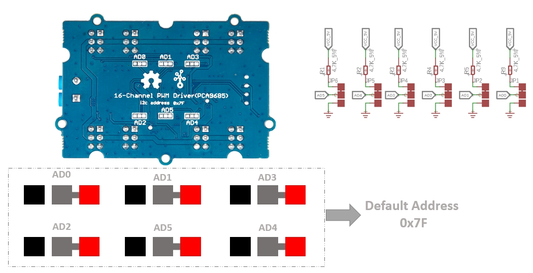
As shown in the figure above, all address pads are connected to the high level by default. The address rules are as shown below:

The address consists of 7 bits and the highest bit is fixed at 1. When we are converting the address to a hexadecimal number, we need to add a 0 to the left of the highest bit.
So the default address is 111 1111, when we add a 0, it becomes 0111 1111 which is 0x7f.
And if we connect all the address pads to the ground, it turns to be 100 0000, when we add a 0, it becomes 0100 0000. Which is 0x40.
Working Principle
Platforms Supported
| Arduino | Raspberry Pi | |||
|---|---|---|---|---|
Getting Started
Play With Arduino
Hardware
Materials required
| Seeeduino V4.2 | Base Shield | Grove - 16-Channel PWM Driver | LED |
|---|---|---|---|
 |  |  |  |
| Get ONE Now | Get ONE Now | Get ONE Now | Get ONE Now |
1 Please plug the USB cable gently, otherwise you may damage the port. Please use the USB cable with 4 wires inside, the 2 wires cable can't transfer data. If you are not sure about the wire you have, you can click here to buy
2 Each Grove module comes with a Grove cable when you buy. In case you lose the Grove cable, you can click here to buy.
3 You also need prepare at least 2 jumper wires, in case you do not have, you can click here to buy.
-
Step 1. Connect red LED to GND and P1 by using dual-female jumper wires.
-
Step 2. Connect the Grove - 16-Channel PWM Driver to port I^2^C of Grove-Base Shield.
-
Step 2. Plug Grove - Base Shield into Seeeduino.
-
Step 3. Connect Seeeduino to PC via a USB cable.

In this example for LED, as we are not using pin '5V' in output group we do not need to power up the power input port. If you want to use servo, you need to connect the 5V pin to the power pin of servo, and you need to offer external power for Power In port.
If you want to use servo, you can connect as shown below:

Software
If this is the first time you work with Arduino, we strongly recommend you to see Getting Started with Arduino before the start.
-
Step 1. Download the Grove-16-Channel_PWM_Driver-PCA9685 Library from Github.
-
Step 2. Refer to How to install library to install library for Arduino.
-
Step 3. Restart the Arduino IDE. Open the example, you can open it in the following three ways:
-
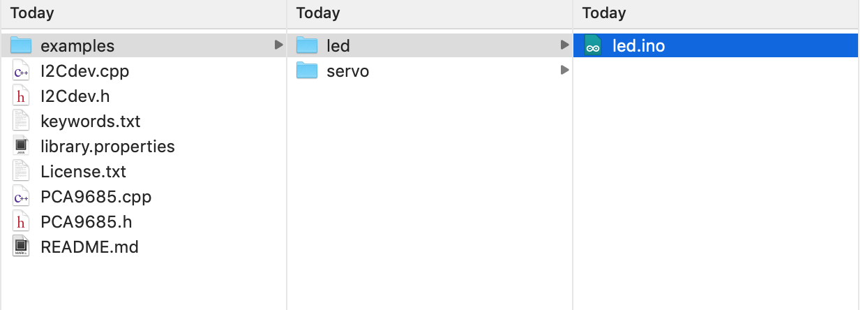
Open it directly in the Arduino IDE via the path: File --> Examples -->Seeed_PCA9685 --> led.

-
Open it in your computer by click the basic_demo.ino which you can find in the folder XXXX\Arduino\libraries\Seeed_PCA9685\examples\led\led.ino, XXXX is the location you installed the Arduino IDE.
-
Or, you can just click the icon
 in upper right corner of the code block to copy the following code into a new sketch in the Arduino IDE.
-
#include "PCA9685.h"
#include <Wire.h>

PCA9685 led;


void setup()
{
    // join I2C bus (I2Cdev library doesn't do this automatically)
    Wire.begin();
    Serial.begin(9600);
    led.init(0x7f);
    // Set freq to 100Hz, range from 24Hz~1526hz
    led.setFrequency(100);

    for (int i=1;i<17;i++){
        led.setPwm(i, 0, 1024);
    }
}

void loop()
{
}
The library file may be updated. This code may not be applicable to the updated library file, so we recommend that you use the first two methods.
If everything goes well, you will be able to see the LED goes on.
Schematic Online Viewer
Resources
-
[PDF] Datasheet PCA9685
Tech Support & Product Discussion
Thank you for choosing our products! We are here to provide you with different support to ensure that your experience with our products is as smooth as possible. We offer several communication channels to cater to different preferences and needs.