Grove - 4-Channel 16-bit ADC(ADS1115)

For microcontrollers without an analog-to-digital converter, or when you need a more accurate ADC. We provide Grove - 4-channel 16-bit ADC(ADS1115), a 4-channel ADC based on Texas Instrument ADS1115, which is a high-precision, low-power, 16-bit ADC chip. It supports 4 single ended inputs or 2 differential inputs. What’s more, it has a programmable data rate range from 8 SPS to 860 SPS with an internal programmable gain (up to x16) for small signals.
The module also contains a Grove port that is internally connected to its channel 0 and channel 1, of which makes it easier to use with Grove Ecosystem.
Feature
- Wide supply range: 2.0V ~ 5.5V, support 3.3 or 5V system
- 16-bit high resolution ADC
- Programmable Data Rate: 8 SPS to 860 SPS
- Internal Programmable Gain: x16 with Internal low-drift voltage reference and oscillator
- The built-in PGA is gain-adjustable and can be controlled by software
- 4 Single-Ended Inputs or 2 Differential Inputs
Specification
| Parameter | Value |
|---|---|
| Input voltage | 3.3V / 5V |
| ADC Resolution | 16 Bit |
| Programmable Data Rate | 8SPS - 860 SPS |
| Channels | 4-channel single-ended input or 2-channel differential input |
| Interface | I2C, Default Address: 0x48 |
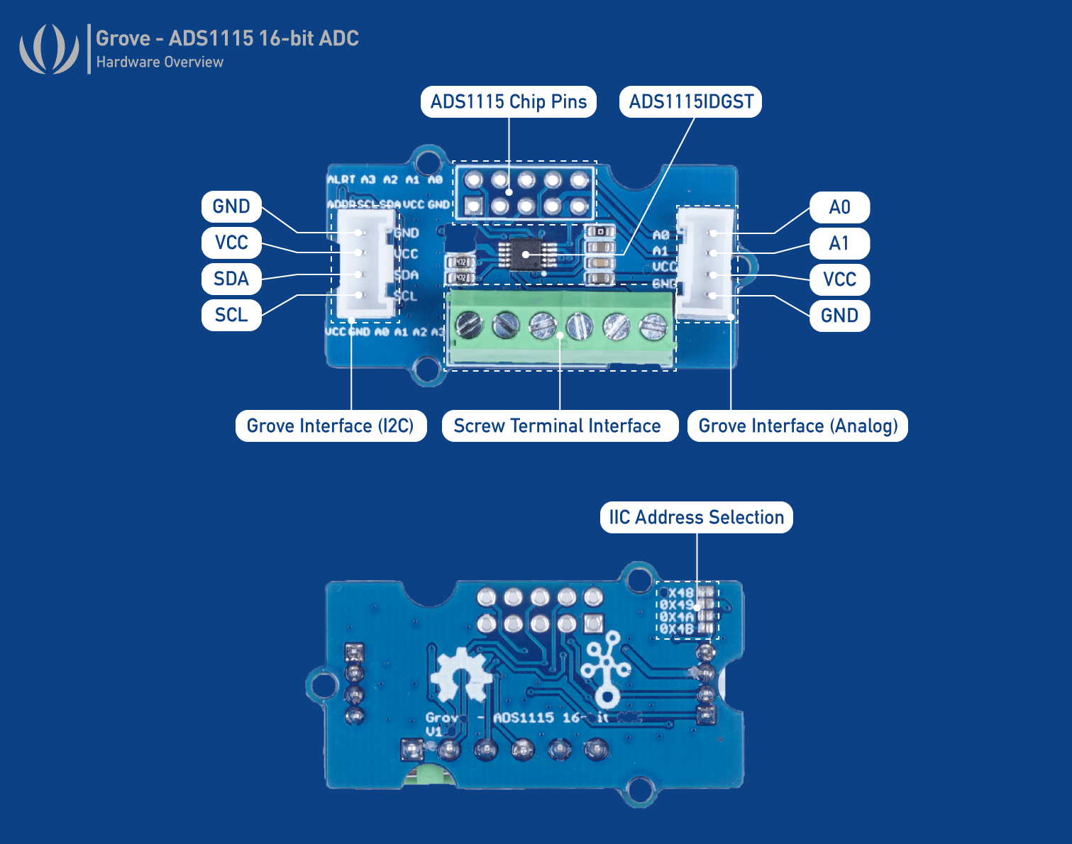
Hardware Overview
Platforms Supported
| Arduino | Raspberry | ArduPy |
|---|---|---|
The platforms mentioned above as supported is/are an indication of the module's software or theoritical compatibility. We only provide software library or code examples for Arduino platform in most cases. It is not possible to provide software library / demo code for all possible MCU platforms. Hence, users have to write their own software library.
Getting Started
Play With Arduino
Materials required
| Seeeduino V4.2 | Base Shield | Grove - 16Bit ADC (ADS1115) |
|---|---|---|
 |  |  |
| Get ONE Now | Get ONE Now | Get ONE Now |
In addition, you can consider our new Seeeduino Lotus M0+, which is equivalent to the combination of Seeeduino V4.2 and Baseshield.
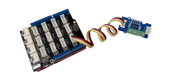
Hardware Connection
-
Step 1. Plug Grove - 16 Bit ADC(ADS1115) to the I2C port of Grove - Base Shield.
-
Step 2. Plug Grove - Base Shield into Seeeduino.
-
Step 3. Connect Seeeduino to a PC via a USB cable.
Software
If this is the first time you work with Arduino, we strongly recommend you to see Getting Started with Arduino before the start.
- Step 1. Download the Seeed Arduino ADS1115 Library from Github.
Refer How to install library to install library for Arduino.
- Step 2. Restart the Arduino IDE. Open Seeed_Arduino_ADS1115 example via the path: File → Examples → Grove - ADS1115 → single_ended.
The single_ended Example code is as follow:
#include "ADS1115.h"

#ifdef SOFTWAREWIRE
    #include <SoftwareWire.h>
    SoftwareWire myWire(3, 2);
    ADS1115<SoftwareWire> ads(myWire);//IIC
#else
    #include <Wire.h>
    ADS1115<TwoWire> ads(Wire);//IIC
#endif

void setup(void)
{
    Serial.begin(115200);
    while(!ads.begin(0x48)){
        Serial.print("ads1115 init failed!!!");
        delay(1000);
    }
    //ads.begin(0x49)
    //ads.begin(0x4A)
    //ads.begin(0x4B)

    ads.setOperateMode(ADS1115_OS_SINGLE);
    ads.setOperateStaus(ADS1115_MODE_SINGLE);

  ads.setPGAGain(ADS1115_PGA_6_144);    // 2/3x gain +/- 6.144V  1 bit =  0.1875mV (default)
    // ads.setPGAGain(ADS1115_PGA_4_096); // 1x gain   +/- 4.096V  1 bit =  0.125mV
    // ads.setPGAGain(ADS1115_PGA_2_048); // 2x gain   +/- 2.048V  1 bit =  0.0625mV
    // ads.setPGAGain(ADS1115_PGA_1_024); // 4x gain   +/- 1.024V  1 bit =  0.03125mV
    // ads.setPGAGain(ADS1115_PGA_0_512); // 8x gain   +/- 0.512V  1 bit =  0.015625mV
    // ads.setPGAGain(ADS1115_PGA_0_256); // 16x gain  +/- 0.256V  1 bit =  0.0078125mV

    ads.setSampleRate(ADS1115_DR_8); //8 SPS
    // ads.setSampleRate(ADS1115_DR_16); //16 SPS
    // ads.setSampleRate(ADS1115_DR_32); //32 SPS
    // ads.setSampleRate(ADS1115_DR_64); //64 SPS
    // ads.setSampleRate(ADS1115_DR_128); //128 SPS
    // ads.setSampleRate(ADS1115_DR_250); //250 SPS
    // ads.setSampleRate(ADS1115_DR_475); //475 SPS
    // ads.setSampleRate(ADS1115_DR_860); //860 SPS
}
void loop(void)
{
    int16_t adc0,adc1,adc2,adc3;
    adc0 = ads.getConversionResults(channel0); //P = AIN0, N = GND
    adc1 = ads.getConversionResults(channel1); //P = AIN1, N = GND
    adc2 = ads.getConversionResults(channel2); //P = AIN2, N = GND
    adc3 = ads.getConversionResults(channel3); //P = AIN3, N = GND
    Serial.print("AIN0: "); Serial.println(adc0);
    Serial.print("AIN1: "); Serial.println(adc1);
    Serial.print("AIN2: "); Serial.println(adc2);
    Serial.print("AIN3: "); Serial.println(adc3);
    Serial.println(" ");
    delay(1000);
}
-
Step 3. Upload the demo. If you do not know how to upload the code, please check How to upload code.
-
Step 4. Open the Serial Monitor of Arduino IDE by click Tool-> Serial Monitor. Or tap the ++ctrl+shift+m++ key at the same time. Set the baud rate to 115200.
-
Step 5. The result should be like this for 4 channels:
In this example, 2/3x gain is set so need to multiply value by 0.1875mV. For example, 10201 x 0.1875mV = 1.91V.
Play With Raspberry Pi
Hardware
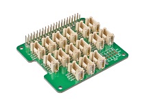
| Raspberry Pi | Grove Base Hat for RasPi | Grove - 16 Bit ADC(ADS1115) |
|---|---|---|
 |  | |
| Get ONE Now | Get ONE Now | Get ONE Now |
Software
The Grove - 16-bit ADC(ADS1115) have the same usage as 4-Channel 16-Bit ADC for Raspberry Pi (ADS1115) and so please follow tutorials here.
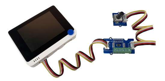
Play with Wio Terminal
Materials required
| Wio Terminal | Grove - 16Bit ADC (ADS1115) | Grove - Rotary Angle Sensor |
|---|---|---|
 | |  |
| Get ONE Now | Get ONE Now | Get ONE Now |
-
Step 1. Plug Grove - 16 Bit ADC(ADS1115) to the I2C port of Wio Terminal.
-
Step 2. Connect Wio Terminal to a PC via a USB cable.
Software
- Step 1. Download the Seeed Arduino ADS1115 Library from Github.
Follow Wio Terminal's get started before the following steps.
-
Step 2. Download the example code here.
-
Step 3. Upload the demo. If you do not know how to upload the code, please check How to upload code.
-
Step 4. Adjust the rotary sensor and you will see the corresponding voltage on Wio Terminal's LCD screen:
Play With Wio Terminal (ArduPy)
Hardware
- Step 1. Prepare the below stuffs:
| Wio Terminal | Grove - 16 Bit ADC(ADS1115) |
|---|---|
| |
| Get One Now | Get One Now |
-
Step 2. Connect Grove - 16 Bit ADC(ADS1115) to I2C port of Wio Terminal.
-
Step 3. Connect the Wio Terminal to PC through USB Type-C cable.
Software
-
Step 1. Follow ArduPy Getting Started to configure the ArduPy development environment on Wio Terminal.
-
Step 2. Make sure that the ArduPy firmware with ADS1115 library is flashed into Wio Terminal. For more information, please follow here.
aip install Seeed-Studio/seeed-ardupy-ads1115
aip build
aip flash
- Step 3. Copy the following code and save it as
ArduPy-ads1115.py:
Note: For more API, please check here.
from arduino import grove_ads1115
import time

ads = grove_ads1115()
ads.setPGAGain(0x0000)

while True:
    print ("The channel0 value is :", ads.channel0)
    print ("The channel1 value is :", ads.channel1)
    print ("The channel2 value is :", ads.channel2)
    print ("The channel3 value is :", ads.channel3)
    time.sleep(1)
- Step 4. Save the
ArduPy-ads1115.pyin a location that you know. Run the following command and replace<YourPythonFilePath>with yourArduPy-ads1115.pylocation.
aip shell -n -c "runfile <YourPythonFilePath>"
# Example:
# aip shell -n -c "runfile /Users/ansonhe/Desktop/ArduPy-ads1115.py"
- Step 5. We will see the ADC value display on terminal as below:
ansonhe@Ansons-Macbook-Pro ~:aip shell -n -c "runfile /Users/ansonhe/Desktop/ArduPy-ads1115.py"
Positional argument (/dev/cu.usbmodem1413101) takes precedence over --open.
Connected to ardupy
The channel0 value is : 17487.0
The channel1 value is : 3790.0
The channel2 value is : 3170.0
The channel3 value is : 3122.0
The channel0 value is : 17486.0
The channel1 value is : 3272.0
The channel2 value is : 3064.0
The channel3 value is : 3063.0
The channel0 value is : 17486.0
The channel1 value is : 3482.0
The channel2 value is : 3201.0
The channel3 value is : 3185.0
The channel0 value is : 17487.0
The channel1 value is : 17261.0
The channel2 value is : 5055.0
The channel3 value is : 4480.0
The channel0 value is : 11839.0
The channel1 value is : 3540.0
The channel2 value is : 1690.0
The channel3 value is : 1562.0
Precautions
When using multi-channel on A0 and A1 on screw terminal, please remember to not connect anything on the Grove Interface as they are also using A0 and A1. THIS MAY BE DANGEROUS WHEN DEALING WITH BATTERIES。
-
When in use, the maximum voltage must not exceed 5.5V.
-
When using the multi-channel acquisition, the sampling frequency must be set above 250SPS, otherwise the sampling frequency is too slow, and there is a possibility that the previous channel is not converted, the next channel is started, resulting in the failure to work
Schematic Online Viewer
Resources
Tech Support & Product Discussion
Thank you for choosing our products! We are here to provide you with different support to ensure that your experience with our products is as smooth as possible. We offer several communication channels to cater to different preferences and needs.