Grove - 3-Axis Digital Accelerometer 200g (ADXL372)

You can find a variety of 3-axis accelerometers on our website that can meet different scenarios and needs. This time, we bring you the industrial grade, high stability, high precision and low power ADI ADXL series three-axis accelerometers.
The Grove - 3-Axis Digital Accelerometer ±200g (ADXL372) is a ultralow power digital output MEMS Accelerometer, it can provide a 12-bit output at 100 mg/LSB scale factor. The most notable feature of this sensor is its ultra-low power consumption(only 22μA in measurment mode) and large measurement range(±200g). All the data output via the Grove I2C port, the I2C address is changeable. In order to meet a wider range of measurement needs, the sampling rate can be selected from 400Hz/800Hz/1600Hz/3200Hz/6400Hz, and the bandwidth can be selected from 200Hz/400Hz/800Hz/1600Hz/3200Hz. In addition to being used as an acceleration measurement, you can also use this module to do impact and shock detection.
The ADI ADXL Series Accelerometer includes four products that will meet your different range and output needs:
| Product | Measurement Range | Output Port | Power Consumption |
|---|---|---|---|
| Grove - 3-Axis Analog Accelerometer ±20g (ADXL356B) | ±10 / ±20g | Analog | measurement mode:150 μA / standby mode:21 μA |
| Grove - 3-Axis Analog Accelerometer ±40g (ADXL356C) | ±10g / ±40g | Analog | measurement mode:150 μA / standby mode:21 μA |
| Grove - 3-Axis Digital Accelerometer ±40g (ADXL357) | ±10g@51200 LSB/g / ±20g@25600 LSB/g / ±40g@12800 LSB/g | Digital I2C | measurement mode:200μA |
| Grove - 3-Axis Digital Accelerometer ±200g (ADXL372) | ±200g | Digital I2C | measurement mode:22μA |
Features
- Large measuring range: ±200g
- Ultralow power consumption: 22 μA at 3200 Hz ODR
- Selectable oversampling ratio and bandwidth
- Deep embedded FIFO to minimize host processor load
- Build-in 12-bit analog-to-digital converter (ADC)
APPLICATIONS
- Portable Internet of Things (IoT) edge nodes
- Concussion and head trauma detection
- Impact and shock detection
- Asset health assessment
Pinout


Specification
| Parameter | Value |
|---|---|
| Supply voltage | 3.3V / 5V |
| Operating ambient temperature | -40 – 125℃ |
| Sensitivity at XOUT, YOUT, ZOUT / (Ratiometric to V1P8ANA) | ±50mg/°C(Nowmal Operation.) / ±35mg/°C(Low Noise Mode.) |
| Sensitivity Change due to Temperature | ±0.01%/°C (TA = −40°C to +125°C) |
| 0g OFFSET | ±1g(.Typ) |
| Output interface | Digital |
Platforms Supported
| Arduino | Raspberry Pi |
|---|---|
|
|
Getting Started
Play With Arduino
Materials required
| Seeeduino V4.2 | Base Shield | Grove 3-aixs Accelermeter ADXL372 |
|---|---|---|
|
|
|
| Get ONE Now | Get ONE Now | Get ONE Now |
In addition, you can consider our new Seeeduino Lotus M0+, which is equivalent to the combination of Seeeduino V4.2 and Baseshield.
1 Please plug the USB cable gently, otherwise you may damage the port. Please use the USB cable with 4 wires inside, the 2 wires cable can't transfer data. If you are not sure about the wire you have, you can click here to buy
2 Each Grove module comes with a Grove cable when you buy. In case you lose the Grove cable, you can click here to buy.
Hardware Connection
-
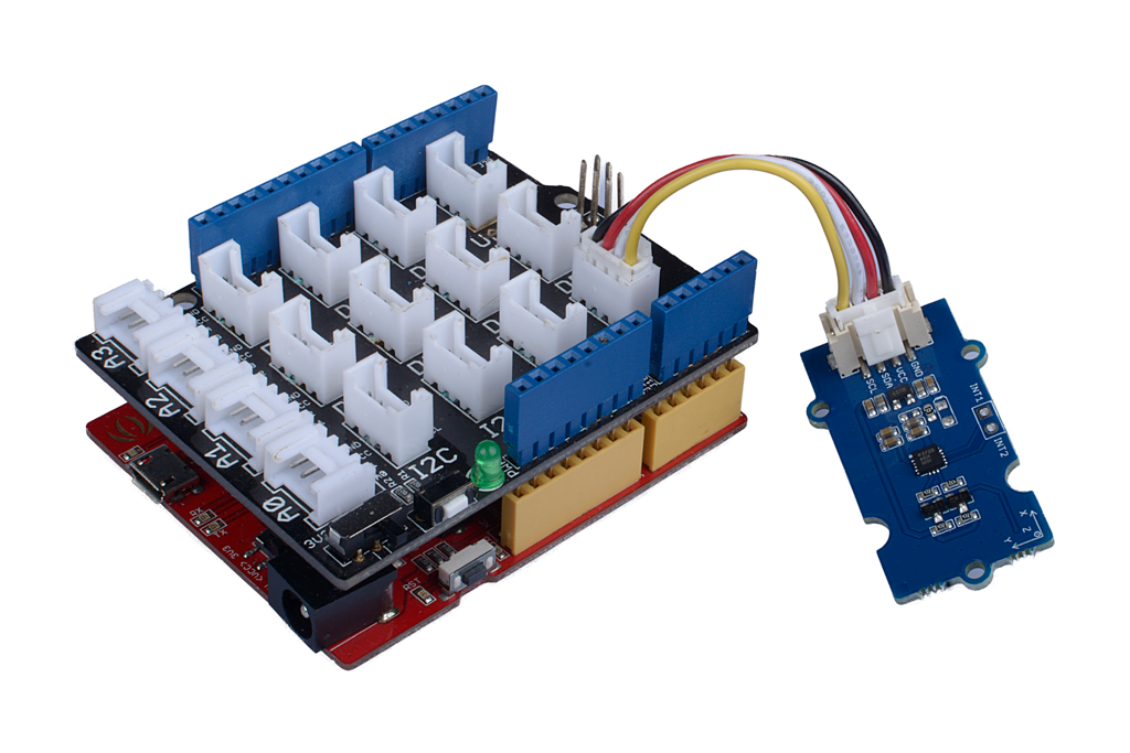
Step 1. Connect the Grove - 3-Axis Analog Accelerometer ±200g (ADXL372) to the I2c port of the Base Shield.
-
Step 2. Plug Grove - Base Shield into Seeeduino.
-
Step 3. Connect Seeeduino to PC via a USB cable.

Software
If this is the first time you work with Arduino, we strongly recommend you to see Getting Started with Arduino before the start.
-
Step 1. Download the Seeed_ADXL_372 library from Github.
-
Step 2. Refer to How to install library to install library for Arduino.
-
Step 3. Then open
example/ADXL_372/continuous_reading

//continuous_reading.ino

#include "Wire.h"
#include "adxl372.h"

#ifdef ARDUINO_SAMD_VARIANT_COMPLIANCE
  #define SERIAL SERIALUSB
  #define SYS_VOL   3.3
#else
  #define SERIAL Serial
  #define SYS_VOL   5
#endif


float cali_data[3];

#define CALI_BUF_LEN           15
#define CALI_INTERVAL_TIME     250

float cali_buf[3][CALI_BUF_LEN];


ADXL372 acc;
xyz_t xyz;

float deal_cali_buf(float *buf)
{
 float cali_val = 0;

 for(int i = 0;i < CALI_BUF_LEN;i++)
 {
  cali_val += buf[i];
 }
 cali_val = cali_val/CALI_BUF_LEN;
 return (float)cali_val;
}


void calibration(void)
{
 SERIAL.println("Please Place the module horizontally!");
 delay(1000);
 SERIAL.println("Start calibration........");


 for(int i=0;i<CALI_BUF_LEN;i++)
 {
  while (!(acc.status() & DATA_READY));
  acc.read(&xyz);
  cali_buf[0][i] = xyz.x;
  cali_buf[1][i] = xyz.y;
  cali_buf[2][i] = xyz.z;
  delay(CALI_INTERVAL_TIME);
  SERIAL.print('.');
 }
 SERIAL.println('.');
 for(int i=0;i<3;i++)
 {
  cali_data[i] =  deal_cali_buf(cali_buf[i]);
  if(2 == i){

   cali_data[i] -= 10;
  }
  SERIAL.println(cali_data[i]);
 }
 SERIAL.println("Calibration OK!!");
}


void setup() {
  SERIAL.begin(115200);

  acc.begin();

  SERIAL.println(acc.id(), HEX);
  acc.timing_ctrl(RATE_400);
  acc.measurement_ctrl(BW_200, true);
  acc.power_ctrl(MEASUREMENT_MODE);
  acc.setActiveTime(10);

  calibration();
}

void loop() {
  if (acc.status() & DATA_READY) {
    acc.read(&xyz);
    SERIAL.print("X position acc = ");
    SERIAL.print((xyz.x - cali_data[0]) / 10.0);
    SERIAL.println(" g ");
    SERIAL.print("Y position acc = ");
    SERIAL.print((xyz.y - cali_data[1]) / 10.0);
    SERIAL.println(" g ");
    SERIAL.print("Z position acc = ");
    SERIAL.print((xyz.z - cali_data[2]) / 10.0);
    SERIAL.println(" mg ");
  }
  SERIAL.println("   ");
  SERIAL.println("   ");
  delay(1000);
}
-
Step 4. Upload the demo. If you do not know how to upload the code, please check How to upload code.
-
Step 5. Open the Serial Monitor of Arduino IDE by click Tool-> Serial Monitor. Or tap the ++ctrl+shift+m++ key at the same time. Set the baud rate to 115200.
-
Step 6. Calibration wait for calibration, just few seconds the calibration will be finished
-
Step 7. Now you can use this sensor, and the output will be like this:
Please Place the module horizontally!
Start calibration........
................
18.07
-10.73
-40.13
Calibration OK!!
X position acc = 0.09 g
Y position acc = 0.17 g
Z position acc = 1.31 mg


X position acc = -0.11 g
Y position acc = -0.03 g
Z position acc = 1.31 mg
Schematic Online Viewer
Resources
Tech Support & Product Discussion
Thank you for choosing our products! We are here to provide you with different support to ensure that your experience with our products is as smooth as possible. We offer several communication channels to cater to different preferences and needs.


