Grove - 4-Channel Solid State Relay

Instead of using coil, packaged solid-state relays(SSR) use power semiconductor devices such as thyristors and transistors, which provide a much faster switching speed than the mechanical relays. The Grove - 4-Channel Solid State Relay is based on the high-quality G3MC202P module, which allows you to use a 5VDC to control MAX. 240VAC. With the help of Grove interface, it becomes very convenient to use the SSR with your arduino.
We use an on-board STM32F030F4P6 to control the channels separately. The command from Arduino or other boards is transmit via the I2C interface, the on-board STM32F030F4P6 will parse the command, so that you can control the switch you want.
According to different application scenarios, we have prepared a series of solid state relays for you.
Grove - 2-Channel Solid State Relay
Grove - 4-Channel Solid State Relay
Grove - 8-Channel Solid State Relay

Features
-
Low power consumption
-
Long lasting
-
Optional I2c address
-
Advantages over mechanical relays:
- Solid-state relays have much faster switching speeds compared with electromechanical relays, and have no physical contacts to wear out
- Totally silent operation
- No physical contacts means no sparking, allows it to be used in explosive environments, where it is critical that no spark is generated during switching
- Increased lifetime, even if it is activated many times, as there are no moving parts to wear and no contacts to pit or build up carbon
- Compact, thin-profile SSR of monoblock construction with an all-in-one lead frame incorporates a PCB, terminals and heat sink, which is much smaller than mechanical relays, and can integrate more channels
-
Disadvantages:
- When closed, higher resistance (generating heat), and increased electrical noise
- When open, lower resistance, and reverse leakage current
- Only works for AC laod
Specification
| Item | Value |
|---|---|
| Operating input voltage | 4~6V |
| Rated Input Voltage | 5V |
| Rated Load Voltage | 100 to 240 VAC 50/60 Hz |
| Load Voltage Range | 75 to 264 VAC 50/60 Hz |
| Load current | 0.1 to 2 A |
| Leakage current | 1.5 mA max. (at 200 VAC) |
| Insulation Resistance | 1,000 MΩ min. (at 500 VDC) |
| Operate Time | 1/2 of load power source cycle +1 ms max. |
| Release Time | 1/2 of load power source cycle + 1 ms max. |
| Storage Temperature | -30°C to 100°C (with no icing or condensation) |
| Operating Temperature | -30°C to 80°C (with no icing or condensation) |
| Operating Humidity | 45% to 85%RH |
| Input Interface | I^2^C |
| Default I^2^C Address | 0x11 or 0x12 |
| Available I^2^C Address | 0x00 ~ 0x7F |
| Output interface | DIP Female Blue 2 pin x4 |
| Zero Cross | support |
| Certification | UL / CSA |
You may pay attention to the Leakage current, 1.5mA is strong enough to drive Low power LED, so when the relay is off, the LED may still emits a faint light.
Applications
- Operations that require low-latency switching, e.g. stage light control
- Devices that require high stability, e.g. medical devices, traffic signals
- Situations that require explosion-proof, anticorrosion, moisture-proof, e.g. coal, chemical industries.
Hardware Overview
Pin Map


- The switch 1-4 have the same pin function, so for the other switches, you can refer to LOAD1/LOAD2.
- On the back of the PCB, there are two interfaces: SWD and I^2^C. The SWD interface is used by default when programming firmware, if you want to use the I^2^C(actually work as the boot UART), you should set the BOOT High.
Schematic
Relay control
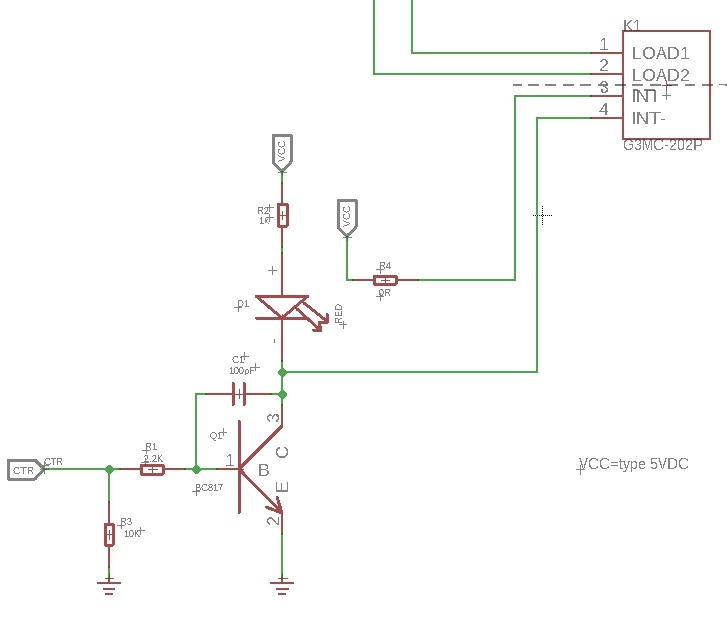
K1 is the Relay module, When a 5V voltage is applied between the INT+ and INT-, the relay will be turned on. Then the LOAD1 will connect to the LOAD2.We use a NPN transistors Q1(BC817-40) to control the voltage between the INT+ and INT-.
The CTR is the control signal from the Arduino or other board. It is pulled down by the 10k R2, if there is no signal, the 'Gate'(port 1) of Q1 will be 0v, and Q1 is turned off, so that the K1 will be turned off. If CTR becomes 5v, then the Q1 will be turned on. INT- of k1 will be connected to the GND of the system, for the K1 there will be 5V between INT+ and INT-, so the K1 will be turned on, and the LOAD1 will connect to LOAD2.
Bi-directional level shifter circuit

This is a typical Bi-directional level shifter circuit to connect two different voltage section of an I^2^C bus. The I2C bus of this sensor use 3.3V, if the I2C bus of the Arduino use 5V, this circuit will be needed. In the schematic above, Q17 and Q18 are N-Channel MOSFET 2N7002A, which act as a bidirectional switch. In order to better understand this part, you can refer to the AN10441
In this section we only show you part of the schematic, for the full document please refer to the Resources
Platforms Supported
| Arduino | Raspberry Pi | |||
|---|---|---|---|---|
The platforms mentioned above as supported is/are an indication of the module's software or theoritical compatibility. We only provide software library or code examples for Arduino platform in most cases. It is not possible to provide software library / demo code for all possible MCU platforms. Hence, users have to write their own software library.
Getting Started
Play With Arduino
Hardware
Materials required
| Seeeduino V4.2 | Base Shield | Grove - 4-Channel Solid State Relay |
|---|---|---|
 |  |  |
| Get One Now | Get One Now | Get One Now |
1 Please plug the USB cable gently, otherwise you may damage the port. Please use the USB cable with 4 wires inside, the 2 wires cable can't transfer data. If you are not sure about the wire you have, you can click here to buy
2 Each Grove module comes with a Grove cable when you buy. In case you lose the Grove cable, you can click here to buy.
-
Step 1. Connect the Grove - 4-Channel Solid State Relay to the I^2^C port of the Base Shield.
-
Step 2. Plug Grove - Base Shield into Seeeduino.
-
Step 3. Connect Seeeduino to PC via a USB cable.

If we don't have Grove Base Shield, We also can directly connect this module to Seeeduino as below.
| Seeeduino | Grove - 4-Channel Solid State Relay |
|---|---|
| 5V | Red |
| GND | Black |
| SDA | White |
| SCL | Yellow |
Software
If this is the first time you work with Arduino, we strongly recommend you to see Getting Started with Arduino before the start.
-
Step 1. Download the Multi_Channel_Relay_Arduino Library from Github.
-
Step 2. Refer to How to install library to install library for Arduino.
-
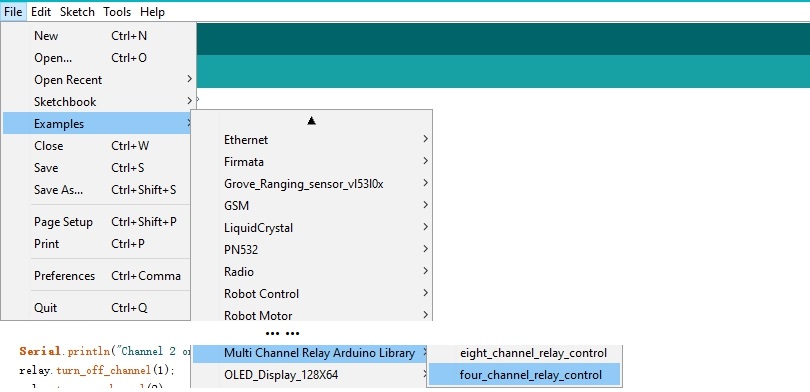
Step 3. Restart the Arduino IDE. Open example via the path: File --> Examples --> Multi Channel Relay Arduino Library --> four_channel_relay_control.
Or, you can just click the icon  in upper right corner of the code block to copy the following code into a new sketch in the Arduino IDE.
#include <multi_channel_relay.h>

Multi_Channel_Relay relay;

void setup()
{
  Serial.begin(9600);
  while(!Serial);

   /* Scan I2C device detect device address */
  uint8_t old_address = relay.scanI2CDevice();
  if((0x00 == old_address) || (0xff == old_address)) {
    while(1);
  }

  Serial.println("Start write address");
  relay.changeI2CAddress(old_address, 0x11);  /* Set I2C address and save to Flash */
  Serial.println("End write address");

  /* Read firmware  version */
  Serial.print("firmware version: ");
  Serial.print("0x");
  Serial.print(relay.getFirmwareVersion(), HEX);
  Serial.println();
}

void loop()
{

  /**
   *  channle: 8 7 6 5 4 3 2 1
   *  state: 0b00000000 -> 0x00  (all off)
   *  state: 0b11111111 -> 0xff  (all on)
  */

  /* Begin Controlling Relay */
  Serial.println("Channel 1 on");
  relay.turn_on_channel(1);
  delay(500);
  Serial.println("Channel 2 on");
  relay.turn_off_channel(1);
  relay.turn_on_channel(2);
  delay(500);
  Serial.println("Channel 3 on");
  relay.turn_off_channel(2);
  relay.turn_on_channel(3);
  delay(500);
  Serial.println("Channel 4 on");
  relay.turn_off_channel(3);
  relay.turn_on_channel(4);
  delay(500);
  relay.turn_off_channel(4);

  relay.channelCtrl(CHANNLE1_BIT |
                    CHANNLE2_BIT |
                    CHANNLE3_BIT |
                    CHANNLE4_BIT);
  Serial.print("Turn all channels on, State: ");
  Serial.println(relay.getChannelState(), BIN);

  delay(2000);

  relay.channelCtrl(CHANNLE1_BIT |
                    CHANNLE3_BIT);
  Serial.print("Turn 1 3 channels on, State: ");
  Serial.println(relay.getChannelState(), BIN);

  delay(2000);

  relay.channelCtrl(CHANNLE2_BIT |
                    CHANNLE4_BIT);
  Serial.print("Turn 2 4 channels on, State: ");
  Serial.println(relay.getChannelState(), BIN);

  delay(2000);


  relay.channelCtrl(0);
  Serial.print("Turn off all channels, State: ");
  Serial.println(relay.getChannelState(), BIN);

  delay(2000);
}
-
Step 4. Upload the demo. If you do not know how to upload the code, please check How to upload code.
-
Step 5. Open the Serial Monitor of Arduino IDE by click Tool-> Serial Monitor. Or tap the ++ctrl+shift+m++ key at the same time.
If every thing goes well, you will get the result. Meanwhile, you will see the on-board LEDs alternately lit and extinguished.
Scanning...
I2C device found at address 0x12 !
Found 1 I2C devices
Start write address
End write address
firmware version: 0x1
Channel 1 on
Channel 2 on
Channel 3 on
Channel 4 on
Turn all channels on, State: 1111
Turn 1 3 channels on, State: 101
Turn 2 4 channels on, State: 1010
Turn off all channels, State: 0
Channel 1 on
Channel 2 on

We do not add load in this demo, if you want to check how to add load, please check the Grove - 2-Channel Solid State Relay.
Function description
| Function | Description |
|---|---|
| changeI2CAddress(uint8_t old_addr, uint8_t new_addr) | change the device address,the old_addr is the current address; the new_addr is the address which you want to use. The new address can be successfully set only by entering the correct old address. |
| scanI2CDevice() | get the old_addr (current address) |
| getChannelState() | get the state of every channel, for instance "State: 1111", which means all the relay is turned on |
| getFirmwareVersion() | get the firmware version burn into the on board MCU |
| channelCtrl(uint8_t state) | to change all channels you picked immediately, the state parameter list: CHANNLE1_BITor 0x01 CHANNLE2_BIT or 0x02 CHANNLE3_BIT or 0x04 CHANNLE4_BIT or 0x08 e.g. channelCtrl(CHANNLE2_BIT|CHANNLE3_BIT),will turn on the channel 2,channel 3 channelCtrl(0x01|0x02|0x08), will turn on the channel 1,channel 2 and channel 4. channelCtrl(0), will turn off all the channels. |
| turn_on_channel(uint8_t channel) | to turn on the single channel. e.g. turn_on_channel(3), will turn on the channel 3 |
| turn_off_channel(uint8_t channel) | to turn off the single channel. e.g. turn_off_channel(3), will turn off the channel 3 |
In case you want to change the address, you need to set the address before use. For example, we want to change it into 0x2f. We can use the following code.
#include <multi_channel_relay.h>

Multi_Channel_Relay relay;

void setup()
{
  Serial.begin(9600);
  while(!Serial);

   /* Scan I2C device detect device address */
  uint8_t old_address = relay. ;
  if((0x00 == old_address) || (0xff == old_address)) {
    while(1);
  }

  Serial.println("Start write address");
  relay.changeI2CAddress(old_address,0x2f);  /* Set I2C address as 0x2f and save it to the EEPRom */
  Serial.println("End write address");

  /* Read firmware  version */
  Serial.print("firmware version: ");
  Serial.print("0x");
  Serial.print(relay.getFirmwareVersion(), HEX);
  Serial.println();
}
FAQ
Q1: How to burn the firmware?
A1: We recommend you use the J-Link burner and the WSD interface to burn the firmware.
You can download the firmware here:
We recommed you use the J-flash for the software:

Schematic Online Viewer
Resources
- [Zip] Grove-4-Channel SPDT Relay eagle files
- [Zip] Multi Channel Relay Arduino Library
- [Bin] Factory firmware
- [PDF] Datasheet of G3MC202P
- [PDF] Datasheet of STM32
Project
This is the introduction Video of this product, simple demos, you can have a try.
Tech Support & Product Discussion
Thank you for choosing our products! We are here to provide you with different support to ensure that your experience with our products is as smooth as possible. We offer several communication channels to cater to different preferences and needs.