Grove - ±5A DC/AC Current Sensor (ACS70331)
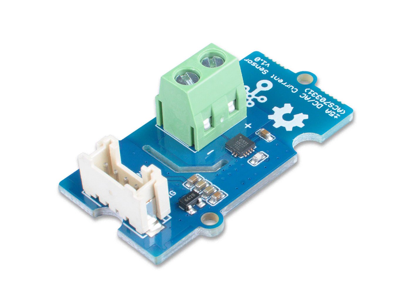
The Grove - ±5A DC/AC Current Sensor (ACS70331) is a high precision DC/AC current sensor based on ACS70331. The ACS70331EESATR-005B3 is Allegro's high sensitivity,current sensor IC for <5 A current sensing applications. It incorporates giant magneto-resistive (GMR) technology that is 25 times more sensitive than traditional Hall-effect sensors to sense the magnetic field generated by the current flowing through the low resistance, integrated primary conductor.
The Grove - ±5A DC/AC Current Sensor (ACS70331) can measure both the DC current and the AC current up to 5A with a base sensitivity of 200mV/A.
There is a measurement data table about current for your reference in Resources part below.

Feature
- Support DC and AC load
- 1 MHz bandwidth with response time <550 ns
- Low noise: 8 mA(rms) at 1 MHz
- 1.1 mΩ primary conductor resistance results in low power loss
- High DC PSRR enables use with low accuracy power supplies or batteries (3 to 4.5 V operation)
- Analog output
Specification
| Parameter | Value |
|---|---|
| Supply voltage | 3.3V / 5V |
| Operating ambient temperature | -40 – 85℃ |
| Storage temperature | - 65°C – 125°C |
| Working Voltage | <100V |
| Current sensing range | 0 – 5A |
| Sensitivity | 200mV/A(Typ.) |
| Output interface | Grove Analog |
| Input interface | Screw terminal |
Working Principle
There are two types of current sensing: direct and indirect. Classification is mainly based on the technology used to measure current.
Direct sensing:
- Ohm's Law
Indirect seneing:
- Faraday's Law of Induction
- Magnetic field sensors
- Faraday Effect
The Grove - ±5A DC/AC Current Sensor (ACS70331) uses magnetic field sensors technology. And there are three kinds of Magnetic field sensors technology:
- Hall effect
- Flux gate sensors
- Magneto-resistive current sensor
The Grove - ±5A DC/AC Current Sensor (ACS70331) is based on the Magneto-resistive current sensor priciple, which is also known as GMR. A magneto-resistor (MR) is a two terminal device which changes its resistance parabolically with applied magnetic field. This variation of the resistance of MR due to the magnetic field is known as the Magnetoresistive Effect.
The internal construction of the ACS70331 QFN package is shown in Figure 2. The die sits above the primary current path such that magnetic field is produced in plane with the GMR elements on the die. GMR elements 1 and 2 sense field in the +X direction for positive IP current flow, and GMR elements 3 and 4 sense field in the –X direction for positive IP current flow. This enables differential measurement of the current and rejection of external stray fields.

The four GMR elements are arranged in a Wheatstone bridge configuration as shown in Figure 2 such that the output of the bridge is proportional to the differential field sensed by the four elements, rejecting common fields.

Hardware Overview

Platforms Supported
| Arduino | Raspberry Pi | |||
|---|---|---|---|---|
Getting Started
The human body is forbidden to touch the module during the test, otherwise there is danger of electric shock.
Play With Arduino
Materials required
| Seeeduino V4.2 | Base Shield | ±5A DC/AC Current Sensor (ACS70331) |
|---|---|---|
 |  |  |
| Get ONE Now | Get ONE Now | Get ONE Now |
In addition, you can consider our new Seeeduino Lotus M0+, which is equivalent to the combination of Seeeduino V4.2 and Baseshield.
1 Please plug the USB cable gently, otherwise you may damage the port. Please use the USB cable with 4 wires inside, the 2 wires cable can't transfer data. If you are not sure about the wire you have, you can click here to buy
2 Each Grove module comes with a Grove cable when you buy. In case you lose the Grove cable, you can click here to buy.
DC Demo
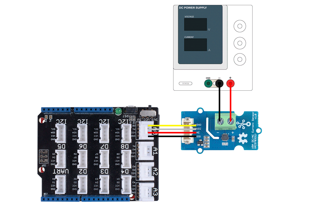
Hardware Connection
-
Step 1. Connect the Grove - ±5A DC/AC Current Sensor (ACS70331) to the A0 port of the Base Shield.
-
Step 2. Connect the positive and negative poles of the circuit to be tested to the corresponding positive and negative poles of the screw terminal.
If you reverse the positive and negative poles, the reading will be reversed. This sensor need calibration before use, so please do not power on the circuit first.
-
Step 3. Plug Grove - Base Shield into Seeeduino.
-
Step 4. Connect Seeeduino to PC via a USB cable.
Software
If this is the first time you work with Arduino, we strongly recommend you to see Getting Started with Arduino before the start.
-
Step 1. Download the Grove Current Sensor Library from Github.
-
Step 2. In the /example/ folder, you can find the demo code. Here we take the Grove - ±5A DC/AC Current Sensor (ACS70331) for instance. Just click the Grove_5A_DC_Current_Sensor.ino to open the demo. Or you can copy the following code:
#ifdef ARDUINO_SAMD_VARIANT_COMPLIANCE
  #define RefVal 3.3
  #define SERIAL SerialUSB
#else
  #define RefVal 5.0
  #define SERIAL Serial
#endif
//An OLED Display is required here
//use pin A0
#define Pin A5

// Take the average of 500 times

const int averageValue = 500;

long int sensorValue = 0;

float sensitivity = 1000.0 / 200.0; //1000mA per 200mV


float Vref = 1508;

void setup()
{
  SERIAL.begin(9600);
}

void loop()
{
  // Read the value 500 times:
  for (int i = 0; i < averageValue; i++)
  {
    sensorValue += analogRead(Pin);

    // wait 2 milliseconds before the next loop
    delay(2);

  }

  sensorValue = sensorValue / averageValue;


  // The on-board ADC is 10-bits
  // Different power supply will lead to different reference sources
  // example: 2^10 = 1024 -> 5V / 1024 ~= 4.88mV
  //          unitValue= 5.0 / 1024.0*1000 ;
  float unitValue= RefVal / 1024.0*1000 ;
  float voltage = unitValue * sensorValue;

  //When no load,Vref=initialValue
  SERIAL.print("initialValue: ");
  SERIAL.print(voltage);
  SERIAL.println("mV");

  // Calculate the corresponding current
  float current = (voltage - Vref) * sensitivity;

  // Print display voltage (mV)
  // This voltage is the pin voltage corresponding to the current
  /*
  voltage = unitValue * sensorValue-Vref;
  SERIAL.print(voltage);
  SERIAL.println("mV");
  */

  // Print display current (mA)
  SERIAL.print(current);
  SERIAL.println("mA");

  SERIAL.print("\n");

  // Reset the sensorValue for the next reading
  sensorValue = 0;
  // Read it once per second
  delay(1000);
}
-
Step 3. Upload the demo. If you do not know how to upload the code, please check How to upload code.
-
Step 4. Open the Serial Monitor of Arduino IDE by click Tool-> Serial Monitor. Or tap the
ctrl+shift+mkey at the same time. Set the baud rate to 9600. -
Step 5. Calibration
When there is no current flowing, the sensor will still have a small output value. We call this value zero offset.
Due to the presence of zero offset, the sensor will also have a reading when there is no current. So we set a parameter Vref to fix it, you can find it in the code block above.
Line 21:
float Vref = 1508;
//Vref is zero drift value, you need to change this value to the value you actually measured before using it.
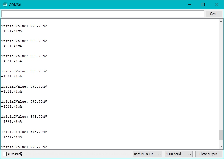
In the demo code, we set the Vref to 1508, however, the zero offset value varies from board to board. As you know, the board we use in this demo is 595.70. So let's modify the Line 21:
float Vref = 596;
//Vref is zero drift value, you need to change this value to the value you actually measured before using it.
Now let's upload the modified code and check the result:

When the current output becomes to 0mA or a small value, you have completed the calibration.
- Step 6. Now it's all yours, you can power up the current. Please feel free to use it, remember this is a 5A Current Sensor, current cannot exceed 5A!
If you want to know the calculation formula of the result, please refer to the FAQ Q1
AC Demo
When you use AC power, please pay attention to safety and avoid electric shock.
For the hardware connection and calibration part, please refer to the DC Demo, the only difference is the code. Please use the following code for AC load.
#ifdef ARDUINO_SAMD_VARIANT_COMPLIANCE
  #define RefVal 3.3
  #define SERIAL SerialUSB
#else
  #define RefVal 5.0
  #define SERIAL Serial
#endif
//An OLED Display is required here
//use pin A0
#define Pin A5

// Take the average of 500 times

const int averageValue = 500;

long int sensorValue = 0;

float sensitivity = 1000.0 / 200.0; //1000mA per 200mV


//float Vref = 244;
float Vref = 1494;

void setup()
{
  SERIAL.begin(9600);
}
static float tempval;
void loop()
{

  // Read the value 500 times:
  for(int i=0;i<20;i++)
  {

  for (int i = 0; i < averageValue; i++)
  {
    int temp;
    temp= analogRead(Pin);
    if(temp>sensorValue)
    {
        sensorValue=temp;
    }
    delayMicroseconds(40);
  }
  tempval+=sensorValue;
  }

  sensorValue=tempval/20.0;
  tempval=0;
  // The on-board ADC is 10-bits
  // Different power supply will lead to different reference sources
  // example: 2^10 = 1024 -> 5V / 1024 ~= 4.88mV
  //          unitValue= 5.0 / 1024.0*1000 ;
  float unitValue= RefVal / 1024.0*1000 ;
  float voltage = unitValue * sensorValue;

  //When no load,Vref=initialValue
  SERIAL.print("initialValue: ");
  SERIAL.print(voltage);
  SERIAL.println("mV");

  // Calculate the corresponding current
  float current = ((voltage - Vref) * sensitivity)*0.707;

  // Print display voltage (mV)
  // This voltage is the pin voltage corresponding to the current

  voltage = unitValue * sensorValue-Vref;
  SERIAL.print(voltage);
  SERIAL.println("mV");


  // Print display current (mA)
  SERIAL.print("current: ")
  SERIAL.print(current);
  SERIAL.println("mA");

  SERIAL.print("\n");


  // Reset the sensorValue for the next reading
  sensorValue = 0;

  // Read it once per second
  delay(1000);
}
FAQ
Q1# What's the current calculation formula?
A1: If you think the principle part is very complicated, let's put it in a easy way. The current in the circuit to be tested excites the magnetic field, which causes the resistance value of the GMR elements change. And the resistance change in the bridge causes a change in the voltage at the output of the chip. We call the voltage output as VIOUT.
VIOUT = Sens × Ip + VIOUT(Q)
Sens: Sens is the coefficient that converts the current into an output voltage. For this module it is 200mA/V.
Ip: Ip is the current value in the circuit to be tested, Unit mA.
VIOUT(Q): VIOUT(Q) is the voltage output when the Ip is 0mA(which means there is no current in the circuit to be tested), Unit mV.
Here comes the current value:
Ip = (VIOUT - VIOUT(Q)) / Sens
Now, Let's review the figure 5, we will explain why the current value of the output is not 0 when the actual current value in the circuit to be tested is 0. As you can see in the figure 5, the initialValue is 595.70mV, which is the VIOUT; the current is -4561.48mA, which is the Ip. As for the VIOUT(Q), it is the Vref we set in the code. In figure 5, it is 1508. And the Sens is 200mA/V, which is 200mA/1000mV. Now, just do some math:
{(595.70mV-1508mV ) / (200mA/1000mV)} = -4561.50mA
So, in the figure 6, when we set the Vref to 595.70, the Ip turns to 0mA.
Schematic Online Viewer
Resources
- [ZIP] Grove - ±5A DC/AC Current Sensor (ACS70331) Schematic file
- [PDF] ACS70331 Datasheet
- [PDF] Measurement Data
Tech Support & Product Discussion
Thank you for choosing our products! We are here to provide you with different support to ensure that your experience with our products is as smooth as possible. We offer several communication channels to cater to different preferences and needs.