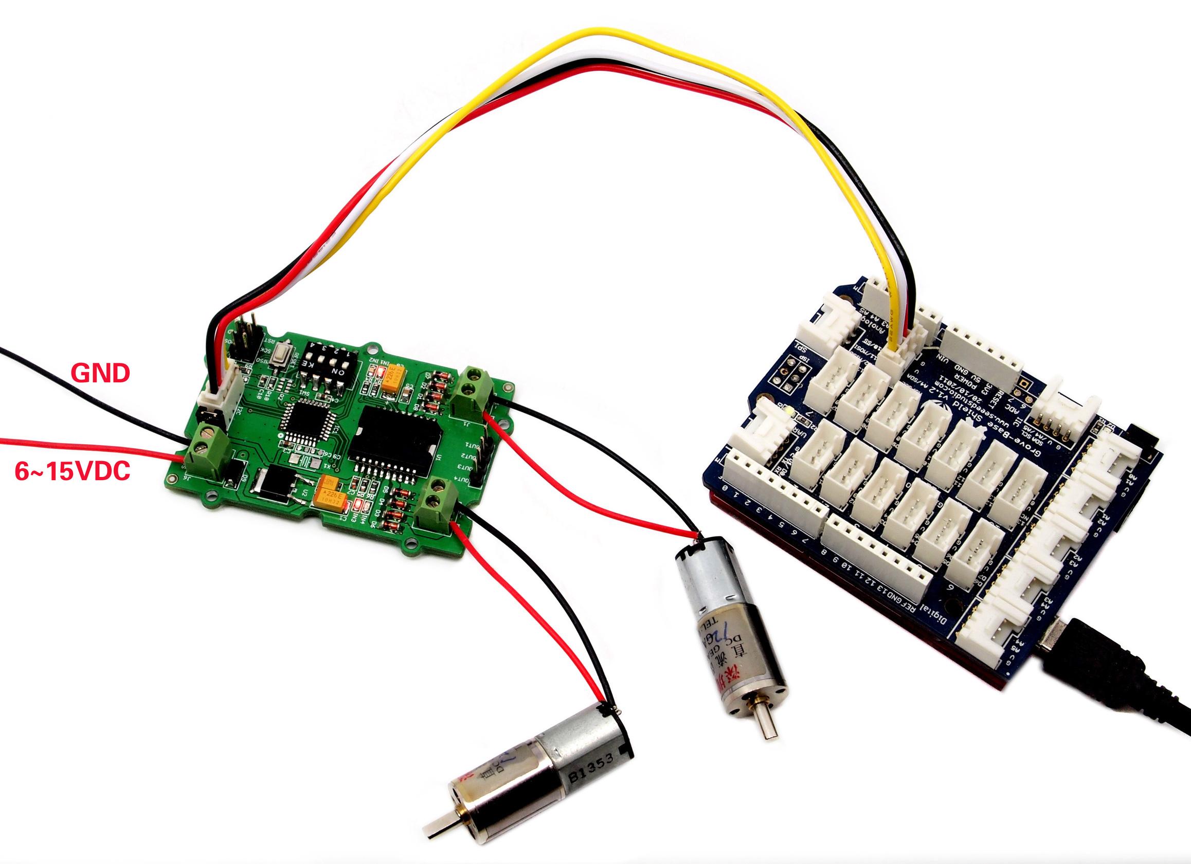
Grove - I2C Motor Driver (L298P)

Grove - I2C Motor Driver(L298P) is a common-use motor driver for stepping motor and servo motor. It embeds an STM32 chip for burning the code to control the motor driver. This is a 2-channel motor driver, each channel can support up to 1A current. You can also use the I2C interface to transmit data from the peripheral microcontroller. The default I2C address is 0x0f and you are able to change the address of Motor driver by connecting the I2C wire hat. The I2C address is selectable from 0x00 to 0x0f.
Features
- MCU: STM32f030f4P6 microcontroller for burning the code and control the Motor Driver.
- L298P Motor driver chip: common use for a motor driver and can drive stepping motor and servo motor.
- Selectable I2C address: change the connection of wire hat to get the I2C address from 0x00 to 0x0f, the default I2C address is 0x0f.
- 2-channel output: able to support 1A current on each channel, max 2A current; Need 6V-12V DC voltage input.
- User LED: green LED on for the clockwise direction and red LED on for the anti-clockwise direction for each channel.
Specification
| Item | Value |
|---|---|
| MCU | STM32f030f4P6 |
| Power Supply | 6-12V DC |
| Interface | Grove I2C |
| I2C address | Default 0x0f, can be changed by connecting the wire hat |
| Channel | 2 |
| Output current | MAX 2A, 1A for each channel |
| Output voltage | 5V |
Platform Supported
| Arduino | Raspberry Pi | |||
|---|---|---|---|---|
 |  |  |  |  |
Getting Started
Use Arduino platform
Materials Requied
| Seeeduino V4.2 | Base Shield | Grove - I2C Motor Driver (L298P) |
|---|---|---|
 |  |  |
| Get One Now | Get One Now | Get One Now |
Hardware connection

-
Step 1 Connect Grove - I2C Motor Driver (L298P) to port I2C of Grove-Base Shield.
-
Step 2 Plug Grove - Base Shield into Seeeduino.
-
Step 3 Connect Seeeduino to PC via a USB cable.
Software Code 1 - DC Motor
#include "Grove_I2C_Motor_Driver.h"

#define I2C_ADDRESS 0x0f /* default I2C address is 0x0f */

void setup() {
    Serial.begin(9600);
    Motor.begin(I2C_ADDRESS);
}

void loop() {
    // Set speed of MOTOR1, Clockwise, speed: -100~100
    Motor.speed(MOTOR1, 50);
    // Set speed of MOTOR2, Anticlockwise
    Motor.speed(MOTOR2, -70);
    delay(2000);
    // Change speed and direction of MOTOR1
    Motor.speed(MOTOR1, -100);
    // Change speed and direction of MOTOR2
    Motor.speed(MOTOR2, 100);
    delay(2000);
    // Stop MOTOR1 and MOTOR2
    Motor.stop(MOTOR1);
    Motor.stop(MOTOR2);
    delay(2000);
}
-
Step 1 Download the Grove_I2C_Motor_Driver_v1_3 Library from Github.
-
Step 2 Refer How to install library to install library for Arduino.
-
Step 3 Copy the code into Arduino IDE and upload. If you do not know how to upload the code, please check how to upload code.
With speed() function, you are able to drive one motor at the speed you want.
-
motor_id represents which motor to use. You can fill MOTOR1 or MOTOR2.
-
_speed represents the speed you set to the motor. You can fill -100~100 here. When _speed>0, DC motor runs clockwise, while_speed<0, DC motor runs anticlockwise. And the bigger the absolute value of _speed, the faster the speed of DC motor.
With stop() function, you are able to stop a running DC motor.
- motor_id represents which motor to use. You can fill MOTOR1 or MOTOR2.
Software Code 2 - Stepper Motor
#include <Grove_I2C_Motor_Driver.h>

#define I2C_ADDRESS 0x0f // default I2C address is 0x0f

void setup() {
    Serial.begin(9600);
    Motor.begin(I2C_ADDRESS);
    // Drive a stepper motor
    // \_step: -1024~1024, when \_step>0, stepper motor runs clockwise; \_step<0, stepper
// motor runs anticlockwise; when \_step is 512, the stepper motor will run a complete
    // turn; if step is 1024, the stepper motor will run 2 turns.
    Motor.StepperRun(-1024);
    Motor.StepperRun(512);
}

void loop() {
    // your code here
}
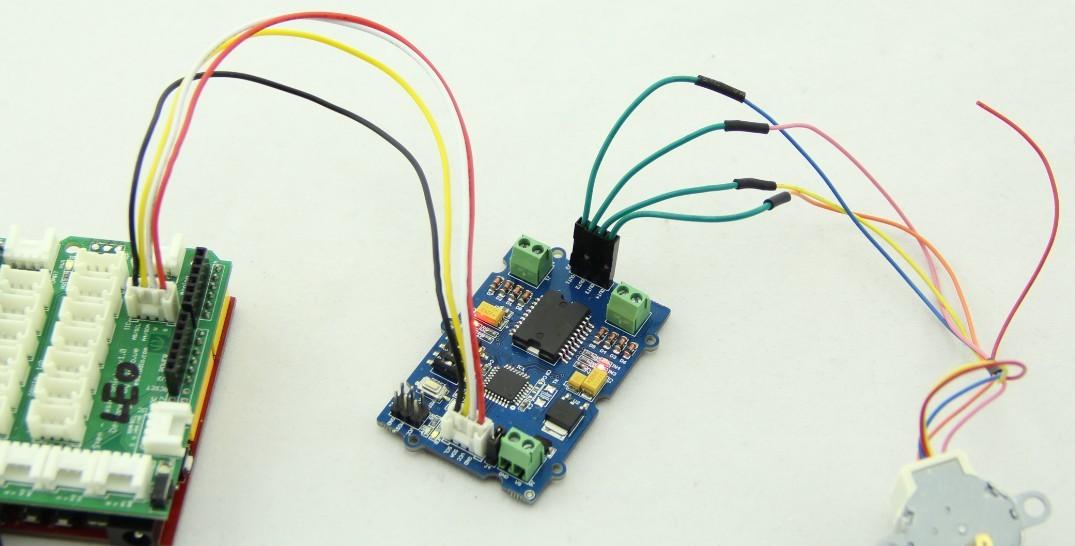
Take 24BYJ48 Stepper Motor as an example, The hardware installation as shown below:

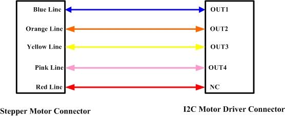
The connection between 24BYJ48 Stepper Motor and I2C Motor Driver is as shown below:

- _step represents the steps you set to the stepper motor to run. You can fill -1024~1024. When _step>0, stepper motor runs clockwise, while_step<0, stepper motor runs anticlockwise. When _step is 512/-512, the stepper motor will run a complete turn and if_step is 1024/-1024, the stepper motor will run 2 turns. The stepper motor will stop automatically after it finishes its steps.
If you encounter a situation where the PWM frequency cannot be changed and remains fixed at 24Hz, it is necessary to update the firmware using a Jlink or ST-link. You can find the new firmware here:
To change the PWM frequency, use Motor.frequence(50) where the value is the frequency, up to a maximum of 255Hz.
Schematic Online Viewer
Resources
-
[PDF] STM32f030f4P6 Datasheet
-
[PDF] L298P Datasheet
-
[PDF] Hardware schematic
-
[Zip] Motor Driver Library
Tech Support & Product Discussion
Thank you for choosing our products! We are here to provide you with different support to ensure that your experience with our products is as smooth as possible. We offer several communication channels to cater to different preferences and needs.