How to detect finger touch
How to Measure Capacitance
The complete capacitance measurement system is composed by sensing electrode pads connected to MPR121 sensing inputs, and the MPR121 communicating with the host processor via I2C bus and interrupt output.

The capacitance measured on each sensing channel is the total capacitance to ground which can be the combination of background parasitic capacitance to ground(Cb) and finger touch induced capacitance to ground(Cx). The MPR121 uses a constant DC charge current scheme for capacitance measurement. Each channel is charged and then discharged completely to ground periodically to measure the capacitance. All the channels are measured sequentially, when one channel is in the charge/discharge and measurement period the other channels are shorted to ground.

The amount of charge(Q)applied is programmable by setting the charge current(I), And the charge time(T). Once the electrode is charged, the peak voltage(V)at the end of chage is measured by internal 10 bit ADC. This voltage V is reverse proportional to the capatance(C)on the sensing channel.
C = Q/V = (I*T)/V
That is, If charge the outside cap with a some value of current(I) and time(T), and get the voltage(V), We can get the value of captance, using this way, the C measureble range can be calculated.
How to Touch Sensing
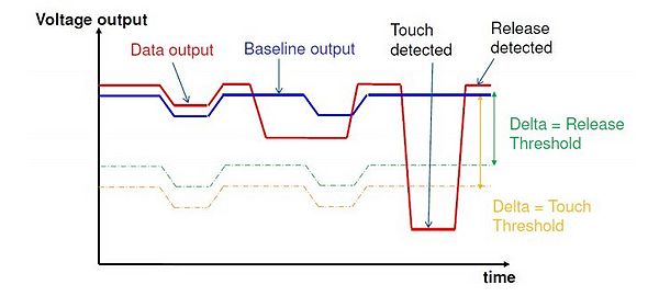
The ADC raw data outputs run through 3 levels of digital filtering to filter out the high frequency and low frequency noise encountered. The first level filter is a simple running average filter, the second level filter result is 10bit and stored in the output data registers as the immediate capacitance of each sensing input, the third level filter result is an even lower frequency content of signal change using the second level filter output, mainly used as the baseline value representing the capacitance variation over the long term and slow environment change such as atmospheric moisture and dirt for touch detection.

Touch and release is determined by comparing the immediate capacitance deviation that is the electrode second level filtered output data deviation to the baseline value. If the deviation passed the setting threshold, then a touch or release status is detected and reported in the status register. The touch and release threshold are independent and individually programmable for each electrode, providing hysteresis and electrode independence. Debounce setting can be used for further noise filtering to provide glitch free touch and release detection.

Tech Support & Product Discussion
Thank you for choosing our products! We are here to provide you with different support to ensure that your experience with our products is as smooth as possible. We offer several communication channels to cater to different preferences and needs.