Wio-E5 mini

LoRaWAN® is a mark used under license from the LoRa Alliance®. The LoRa® Mark is a trademark of Semtech Corporation or its subsidiaries.
Wio-E5 mini is a compacted-sized development board suitable for the rapid testing and building of small-size prototyping and helps you design your ideal LoRaWAN® wireless IoT device with a long-distance transmission range.
Wio-E5 mini is embedded with Wio-E5 STM32WLE5JC Module, which delivers the world-first combo of LoRa® RF and MCU chip into one single tiny chip and is FCC and CE certified. It is powered by ARM Cortex-M4 core and Semtech SX126X LoRa® chip and supports LoRaWAN® protocol on the worldwide frequency and (G)FSK, BPSK, (G)MSK, and LoRa® modulations.
Learn more about Wio-E5 here.
More comparison between the Wio-E5 and LoRa® RFM95 chip:

Wio-E5 mini leads out all GPIOs of Wio-E5, including UART, ADC, SPI, IIC, and etc. It contains RESET and BOOT buttons and is use-friendly. Supporting LoRaWAN® protocol, Wio-E5 mini features ultra-long-range transmission and ultra-low power consumption: it is able to achieve a transmission range of up to 10 km, and the sleep current of Wio-E5 modules on board is as low as 2.1 uA(WOR mode). It is designed with industrial standards with a wide working temperature at -40 ℃ ~ 85℃, high sensitivity between -116.5dBm ~ -136 dBm, and RF output power up to +20.8 dBm at 3.3V.
Other than the Wio-E5 mini, we also provide other choices including the Wio-E5 Development Board carrying more complex interfaces and features to unlock the more powerful performance of the Wio-E5 module. It provides a broader range of access protocols and superabundant types of interfaces. Thus you are able to test and prototype the module rapidly with RS-485, Grove interfaces, and rich GPIOs. (Learn more about Wio-E5 Development Board)
Since Wio-E5 is a LoRaWAN® chip with an MCU, there are three main ways to utilize the Wio-E5 mini:
1. Connect Wio-E5 mini to PC and control by AT commands
There is a built-in USB to UART function on board, you could connect the Wio-E5 mini to your PC with a USB type C cable, and use serial communication software to send AT commands and read data from the board.
2. Connect Wio-E5 mini to another mainboard via UART and control by AT commands
For example, connect Wio-E5 mini to Seeeduino XIAO and the Expansion Board via UART, and send AT commands and read data from Seeeduino XIAO through Arduino IDE serial monitor.
3. User Application Development by using SDK
Develop your own LoRa® development board with MCU function by using STM32Cube Programmer, which is the SDK officially provided by STMicroelectronics. To download this SDK resource, please find the resources in learning and document down below.
With all the outstanding features listed above, the Wio-E5 mini will be a superior choice for IoT device development, testing, prototyping, and applications in long-distance, ultra-low power consumption IoT scenarios like smart agriculture, smart office, and smart industry.
If you are unfamiliar with LoRa® and LoRaWAN® technology, please check out this blog LoRa®pedia in detail.
Features
-
Full GPIOs led out from the Wio-E5 STM32WLE5JC
-
Global LoRaWAN® and LoRa® frequency plan supported
-
Long-distance transmission range to 10km (ideal value in open area)
-
Mini and compact size, suitable for rapid testing and building small size prototype
-
Convenient RESET and BOOT buttons on board
Hardware Overview


Specifications
| Parameters | Specifications |
|---|---|
| size | 50*23mm |
| voltage - supply | 3.7V - 5V |
| power - output | up to +20.8 dBm at 3.3V |
| working frequency | 868/915MHz |
| protocol | LoRaWAN® |
| sensitivity | -116.5 dBm ~ -136 dBm |
| interfaces | USB Type C / 2P-2.54mm Hole / 112P-2.54mm Header2 / SMA-K / IPEX |
| modulation | LoRa®, (G)FSK, (G)MSK, BPSK |
| working temperature | -40℃ ~ 85℃ |
| current | Wio-E5 module sleep current as low as 2.1uA (WOR mode) |
| Part List: | |
|---|---|
| Wio-E5 mini *1 | |
| Antenna(EU868/US915)*1 | |
| USB TypeC (20cm) *1 | |
| Sticker*1 | |
| 1X12pin male pin headers *2 |
Applications
- Wio-E5 module Easy testing
- Rapid small-dimension prototyping of LoRa® devices with Wio-E5
- Any long-distance wireless communication application development
- LoRa® and LoRaWAN® application learn and research

Application Notes
1. Factory AT Firmare
wio-E5 series has a built-in AT command firmware, which supports LoRaWAN® Class A/B/C protocol and a wide frequency plan: EU868/US915/AU915/AS923/KR920/IN865. With this AT command firmware, developers can easily and quickly build their prototype or application.
The AT command firmware contains a bootloader for DFU and the AT application. The "PB13/SPI_SCK/BOOT" pin is used to control Wio-E5 to stay in the bootloader or jump to the AT application. When PB13 is HIGH, the module will jump to AT application after reset, with a default baud rate of 9600. When PB13 is LOW (press the "Boot" button on Wio-E5 mini), the module will stay in the bootloader, and keep transmitting "C" character every 1S at baud rate 115200.
- Factory AT Firmware is programmed with RDP(Read Protection) Level 1, developers need to remove RDP first with STM32Cube Programmer. Note that regression RDP to level 0 will cause a flash memory mass to erase and the Factory AT Firmware can't be restored again.
- The "PB13/SPI_SCK/BOOT" pin on the Wio-E5 module is just a normal GPIO, not the "BOOT0" pin of the MCU. This "PB13/SPI_SCK/BOOT" pin is used in the bootloader of the Factory AT firmware, to decide to jump to APP or stay in bootloader(for DFU). The real "BOOT0" pin doesn't pinout to the module, so users need to be careful when developing the low-power applications
2. Clock Configuration
2.1 HSE
-
32MHz TCXO
-
TCXO power supply: PB0-VDD_TCXO
2.2 LSE
- 32.768KHz crystal oscillator
3. RF Switch
Wio-E5 module ONLY transmits through RFO_HP:
-
Receive: PA4=1, PA5=0
-
Transmit(high output power, SMPS mode): PA4=0, PA5=1
Getting Started
Quick start of AT Commands
Preparation
-
Step 1. Connect Wio-E5 mini to PC via a Type-C cable
-
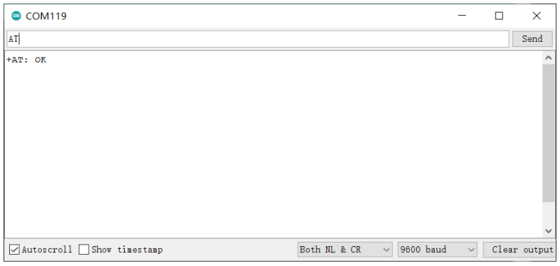
Step 2. Open a serial tool(eg. Arudino Serial Monitor), select the right COM port, set baudrate to 9600 and select Both NL & CR
-
Step 3. Try to send "AT" and you will see the response.
Basic AT Commands
| Command Format | Return | Description |
|---|---|---|
| AT | +AT: OK | Test command |
| AT+VER | +VER: $MAJOR.$MINOR.$PATCH +VER: 4.0.11 | Check Firmware version |
| AT+ID // Read all, DevAddr( ABP), DevEui( OTAA), AppEui( OTAA) AT+ID = DevAddr // Read Device Address AT+ID = DevEui // Read DevEui AT+ID = AppEui // Read AppEui | +ID: DevAddr, xx: xx: xx:xx +ID: DevEui, xx:xx:xx:xx:xx:xx:xx:xx +ID: AppEui13, xx:xx:xx:xx:xx:xx:xx | Use to check the ID of the LoRaWAN module. ID is treated as big endian numbers. |
| AT+ID = DevAddr, “01234567” // Set new DevAddr AT+ID = DevEui, “0123456789ABCDEF” // Set new DevEui AT+ID = AppEui, “0123456789ABCDEF” // Set new AppEui | +ID: DevAddr, 01:23:45:67 +ID: DevEui, 01:23:45:67:89:AB:CD:EF +ID: AppEui, 01:23:45:67:89:AB:CD:EF | Change the ID |
| AT+RESET | +RESET: OK | Reset the module |
| AT+MSG=”Data to send” | +MSG: Start +MSG: FPENDING // Downlink frame FPENDING flag is set +MSG: Link 20, 1 +MSG: ACK Received // LinkCheckAns received + MSG: MULTICAST // Downlink frame is multi cast message +MSG: PORT: 8; RX: "12345678" //Downlink message is received +MSG: RXWIN2, RSSI -106, SNR 4 //Downlink frame signal strength +MSG: Done | send string format frame which is no need to be confirmed by the server |
| AT+PORT = “port” eg: AT+PORT = 8 //Set port to 8 | + PORT: 8 | Set port number which will be used by MSG/CMSG/MSGHEX/CMSGHEX command to send message, port number should range from 1 to 255. |
| AT+ADR=" state" eg: AT+ADR=ON // Enable ADR function AT+ ADR= OFF // Disable ADR function AT+ADR=? // Check current ADR configuration | +ADR: ON // ADR query/ set return | Set ADR function of LoRaWAN module |
| AT+DR // Check current selected DataRate AT+DR=drx // "drx" should range 0~15 | +DR: DR0 +DR: US915 DR0 SF10 BW12 | Use LoRaWAN defined DRx to set datarate of LoRaWAN AT modem. |
| AT+ DR= band //" band" could be band names defined in Chapter3 Band Plans AT+ DR= SCHEME // Check current band | (EU868) +DR: EU868 +DR: EU868 DR0 SF12 BW125K +DR: EU868 DR1 SF11 BW125K +DR: EU868 DR2 SF10 BW125K +DR: EU868 DR3 SF9 BW125K +DR: EU868 DR4 SF8 BW125K +DR: EU868 DR5 SF7 BW125K +DR: EU868 DR6 SF7 BW125K +DR: EU868 DR7 FSK +DR: EU868 DR8 RFU +DR: EU868 DR9 RFU +DR: EU868 DR10 RFU +DR: EU868 DR11 RFU +DR: EU868 DR12 RFU +DR: EU868 DR13 RFU +DR: EU868 DR14 RFU +DR: EU868 DR15 RFU | Data rate scheme |
| AT + CH // query all channels AT + CH = ch // check single channel frequency | Query Channel Configuration | |
| AT+CH="chn", ["freq"], ["drmin"], ["drmax"] // Change the chn channel frequency to "Freq" // "freq" is in MHz. // Available "drmin"/"drmax" range DR0 ~ DR15 | +CH: 3,433700000,DR0:DR5 +CH: 3,433700000,DR | Set channel parameter of LoRaWAN modem, Set frequency zero to delete one channel. |
| AT+CH=chn,ON AT+CH=chn, OFF | Enable or Disable Channel | |
| AT+ KEY= NWKSKEY, “ 16 bytes length key” eg: AT+KEY=NWKSKEY, "2B7E151628AED2A6ABF7158809CF4F3C" eg: AT+KEY=NWKSKEY, "2B 7E 15 16 28 AE D2 A6 AB F7 15 88 09 CF 4F 3C” | + KEY: NWKSKEY 2B7E151628AED2A6ABF7158809CF4F3C | Change network session key (NWKSKEY) |
| AT+ KEY= APPSKEY, “ 16 bytes length key” eg: AT+KEY=APPSKEY, "2B7E151628AED2A6ABF7158809CF4F3C" eg: AT+KEY= APPSKEY, "2B 7E 15 16 28 AE D2 A6 AB F7 15 88 09 | + KEY: APPSKEY 2B7E151628AED2A6ABF7158809CF4F3C | Change application session key (APPSKEY) |
| AT+ FDEFAULT AT+ FDEFAULT= Seeed | +FDEFAULT: OK | Reset LoRaWAN AT modem to factory default configuration |
| T+ DFU=" New state" eg: AT+DFU=ON // Enable DFU function eg: AT+DFU=OFF //Disable DFU function AT+DFU=? // Check if DFU is enabled configuration | +DFU: ON +DFU: OFF | Use to enter DFU mode |
| T+MODE="mode" eg: AT+MODE=TEST // Enter TEST mode eg: AT+MODE= LWOTAA // Enter LWOTAA mode eg: AT+MODE= LWABP // Enter LWABP mode | +MODE: LWABP // Enter TEST mode successfully +MODE: LWOTAA // Enter LWOTAA mode successfully +MODE: TEST // Enter TEST mode successfully | Use to select work mode |
| AT + JOIN AT + JOIN = FORCE | a) Join successfully +JOIN: Starting + JOIN: NORMAL +JOIN: NetID 000024 DevAddr 48:00:00:01 +JOIN: Done b) Join failed +JOIN: Join failed c) Join process is ongoing + JOIN: LoRaWAN modem is busy | When OTAA mode is enabled, JOIN command could use to join a known network |
For more information, refer to the Command Specification.
Connect and send data to The Things Network
-
Step 1. Visit The Things Network website and sign up for a new account
-
Step 2. After logging in, click your profile and select Console

- Step 3. Select a cluster to start adding devices and gateways

- Step 4. Click Go to applications

- Step 5. Click + Add application

- Step 6. Fill Application ID and click Create application

Note: Here Application name and Description are not compulsory fields. If Application name is left blank, it will use the same name as Application ID by default
The following is the newly created application

- Step 7. Click + Add end device

- Step 8. Click Manually, to enter the registration credentials manually

- Step 9. Select the Frequency plan according to your region. Also make sure you use the same frequency as the gateway in which you will connect this device to. Select MAC V1.0.2 as the LoRaWAN® version and PHY V1.0.2 REV B as the Regional Parameters version. These settings are according to the LoraWAN® stack of Wio-E5.

-
Step 10. While the Wio-E5 module is still accessible over the serial console, send the following AT commands on the serial monitor:
AT+ID=DevEuito get your Device EUIAT+ID=AppEui, to get your App EUIAT+KEY=APPKEY,"2B7E151628AED2A6ABF7158809CF4F3C"to set the App Key
The output will be as follows:
Tx: AT+ID=DevEui
Rx: +ID: DevEui, 2C:F7:F1:20:24:90:03:63
Tx: AT+ID=AppEui
Rx: +ID: AppEui, 80:00:00:00:00:00:00:07
Tx: AT+KEY=APPKEY,"2B7E151628AED2A6ABF7158809CF4F3C"
Rx: +KEY: APPKEY 2B7E151628AED2A6ABF7158809CF4F3C
- Step 11. Copy and paste the above information into DevEUI, AppEUI and AppKey fields. End device ID field will be automatically filled when we fill DevEUI. Finally click Register end device

-
Step 12. Register your LoRaWAN® Gateway with TTN Console. Please refer to the instructions shown here
-
Step 13. Type the following AT commmands to connect to TTN
// If you are using US915
AT+DR=US915
AT+CH=NUM,8-15

// If you are using EU868
AT+DR=EU868
AT+CH=NUM,0-2

AT+MODE=LWOTAA
AT+JOIN
The output on serial monitor will be as follows:
Tx: AT+DR=US915
Rx: +DR: US915
Tx: AT+CH=NUM,8-15
Rx: +CH: NUM, 8-15

Tx: AT+MODE=LWOTAA
Rx: +MODE: LWOTAA

Tx: AT+JOIN
Rx: +JOIN: Start
+JOIN: NORMAL
+JOIN: Network joined
+JOIN: NetID 000013 DevAddr 26:01:5F:66
+JOIN: Done
If you see +JOIN: Network joined on your serial console, that means your device has successfully connected to TTN!
You can also check your device status on the End devices page

- Step 14. Type the following AT commands to send data to TTN
// send string "HELLO" to TTN
Tx: AT+MSG=HELLO
Rx: +MSG: Start
+MSG: FPENDING
+MSG: RXWIN2, RSSI -112, SNR -1.0
+MSG: Done
// send hex "00 11 22 33 44"
Tx: AT+MSGHEX="00 11 22 33 44"
Rx: +MSGHEX: Start
+MSGHEX: Done
For more information about AT Commands, please refer to Wio-E5 AT Command Specification
Develop with STM32Cube MCU Package
This section is for Wio-E5 mini, aiming at building several applications with STM32Cube MCU Package for STM32WL series(SDK).
Note: We have now updated the library to support v1.1.0 which is the latest version of STM32Cube MCU Package for STM32WL series.
Please read Erase Factory AT Firmware section first, as if we need to erase the Factory AT Firmware before we program with SDK. After erasing the Factory AT Firmware it CANNOT be recovered.
Preparations
Software:
-
STM32CubeIDE: for compilation and debugging
-
STM32CubeProgrammer: for programming STM32 devices
Hardware:
-
LoRaWAN® Gateway connected to LoRaWAN® Network Server (e.g. TTN)
-
A USB Type-C cable and a ST-LINK. Connect the Type-C cable to the Type-C port of the board for power and serial communication. Connect the ST-LINK to the SWD pins as follows

GPIO Configuration Overview
- As the hardware design of Wio-E5 series is a bit different with NUCLEO-WL55JC, the official STM32WL55JC development board from ST, developers need to reconfigure some gpios, to adapt the SDK example to Wio-E5 series. We have already reconfigured GPIOs, but we think it is nessary to point out the difference.
| SDK Example Label | GPIO of NUCLEO-WL55JC | GPIO of Wio-E5 mini |
|---|---|---|
| RF_CTRL1 | PC4 | PA4 |
| RF_CTRL2 | PC5 | PA5 |
| RF_CTRL3 | PC3 | None |
| BUT1 | PA0 | PB13 (Boot Button) |
| BUT2 | PA1 | None |
| BUT3 | PC6 | None |
| LED1 | PB15 | None |
| LED2 | PB9 | PB5 |
| LED3 | PB11 | None |
| PROB1 | PB12 | PA0 (D0 Button) |
| PROB2 | PB13 | PB10 |
| PROB3 | PB14 | PB3 |
| PROB4 | PB10 | PB4 |
| Usart | Usart2(PA2/PA3) | Usart1(PB6/PB7) |
The label PROB refers to the pin of Probe Line. These pins are able to set as the CM4_EVENTOUT additional function. As part of the CoreSight debugging components of Arm Cortex-M4 kernel, this feature enables non-intrusive debugging and hardware-level event tagging. It monitors CPU internal activities in real time without pausing the CPU or occupying communication interfaces (such as UART), converting “events” that are difficult to observe directly in software into measurable electrical signals.
Applications
Now we will explore several applications for Wio-E5 mini with STM32Cube MCU Package for STM32WL series(SDK).
LoRaWAN® End Node
This application will connect Wio-E5 mini with TTN (The Things Network) and send data after connecting with a LoRaWAN® gateway.
- Step 1. Click here to visit Seeed-Studio/LoRaWan-E5-Node repository and download it as a ZIP file

-
Step 2. Extract the ZIP file and navigate to
LoRaWan-E5-Node > Projects > Applications > LoRaWAN > LoRaWAN_End_Node > STM32CubeIDE -
Step 3. Double click the .project file
Note: For MAC, it should take one of the options below to open the project:
-
1. Navigate to
Wio-E5-Node > Projects > Applications > LoRaWAN > LoRaWAN_End_Node. Doulble click file "LoRaWAN_End_Node.ioc". -
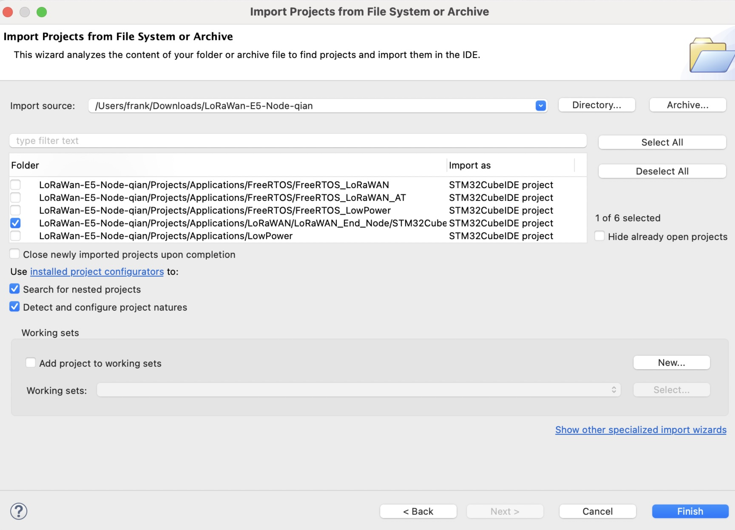
2. Use "Import Projects from File System or Archieve" like below images.
-
- Step 4. Right click on the project and click Properties

- Step 5. Navigate to
C/C++ Build > Settings > MCU Post build outputs, tick Convert to Intel Hex file (-O ihex) and click Apply and Close

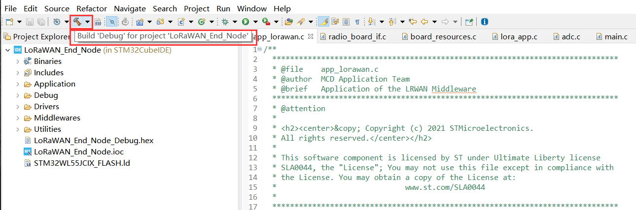
- Step 6. Click Build 'Debug', and it should compile without any errors

Now we will modify our Device EUI, Application EUI, Application KEY and LoRawan® Region
- Step 7. Please follow the guide here to setup your TTN application, get your Application EUI and copy it to the macro definition
LORAWAN_JOIN_EUIinLoRaWAN/App/se-identity.h, for example, the Application EUI here is80 00 00 00 00 00 00 0x07:
// LoRaWAN/App/se-identity.h

/*!
 * App/Join server IEEE EUI (big endian)
 */
#define LORAWAN_JOIN_EUI                                   { 0x80, 0x00, 0x00, 0x00, 0x00, 0x00, 0x00, 0x07 }
- Step 8. Also, you can modify your Device EUI and Application Key, by setting the macro definition
LORAWAN_DEVICE_EUIandLORAWAN_NWK_KEYinLoRaWAN/App/se-identity.h. Make sureLORAWAN_DEVICE_EUIandLORAWAN_NWK_KEYare the same as theDevice EUIandApp Keyin TTN console.
// LoRaWAN/App/se-identity.h

/*!
 * end-device IEEE EUI (big endian)
 */
#define LORAWAN_DEVICE_EUI                                 { 0x2C, 0xF7, 0xF1, 0x20, 0x24, 0x90, 0x03, 0x63 }

/*!
 * Network root key
 */
#define LORAWAN_NWK_KEY                                    2B,7E,15,16,28,AE,D2,A6,AB,F7,15,88,09,CF,4F,3C

- Step 9. The default LoRaWAN Region is
EU868, you can modify it, by setting the macro definitionACTIVE_REGIONinLoRaWAN/App/lora_app.h
// LoRaWAN/App/lora_app.h

/* LoraWAN application configuration (Mw is configured by lorawan_conf.h) */
/* Available: LORAMAC_REGION_AS923, LORAMAC_REGION_AU915, LORAMAC_REGION_EU868, LORAMAC_REGION_KR920, LORAMAC_REGION_IN865, LORAMAC_REGION_US915, LORAMAC_REGION_RU864 */
#define ACTIVE_REGION                               LORAMAC_REGION_US915

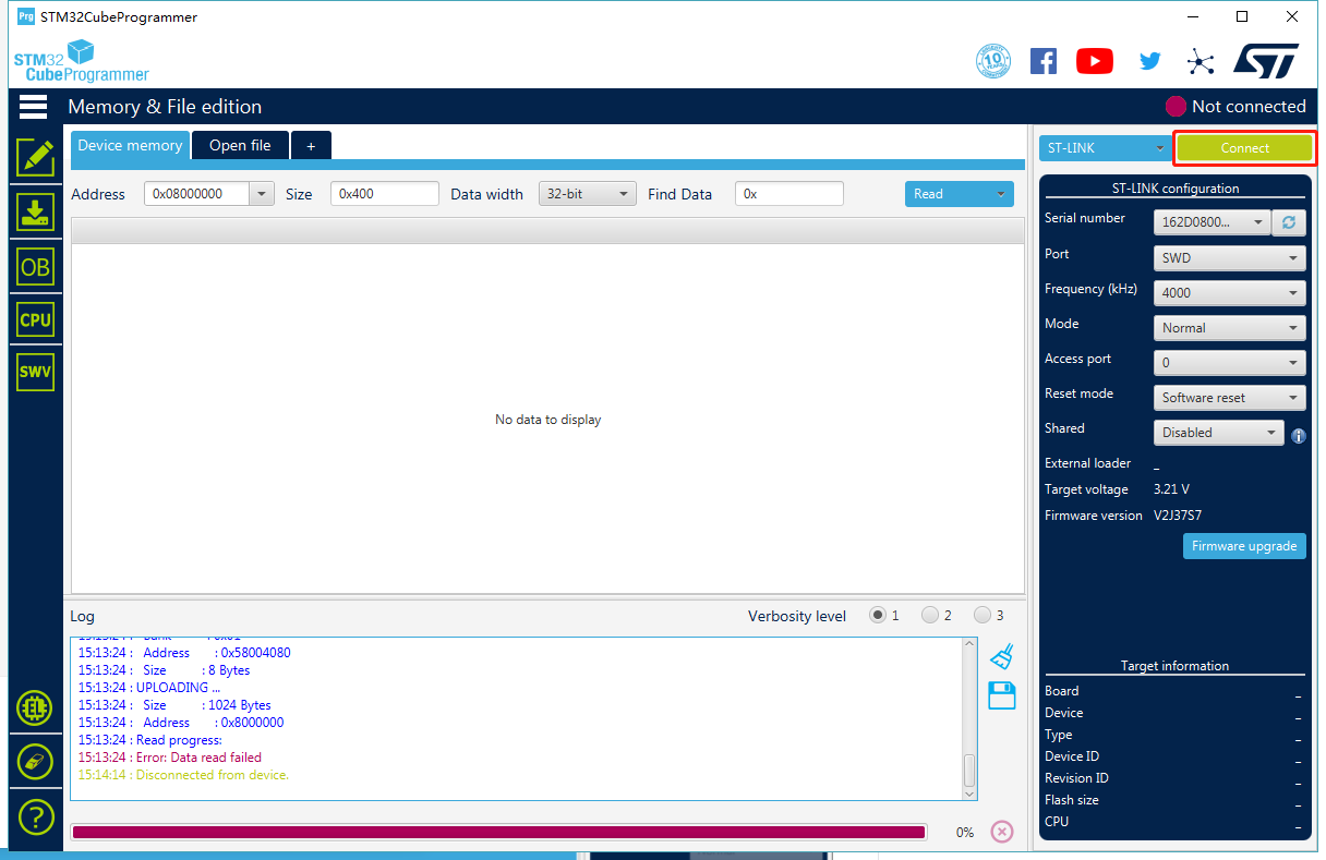
- Step 10. After the above modifications, rebuild the example and program to your Wio-E5. Open
STM32CubeProgrammer, connect ST-LINK to your PC, holdRESET Buttonof your Device, then clickConnectand releaseRESET Button:
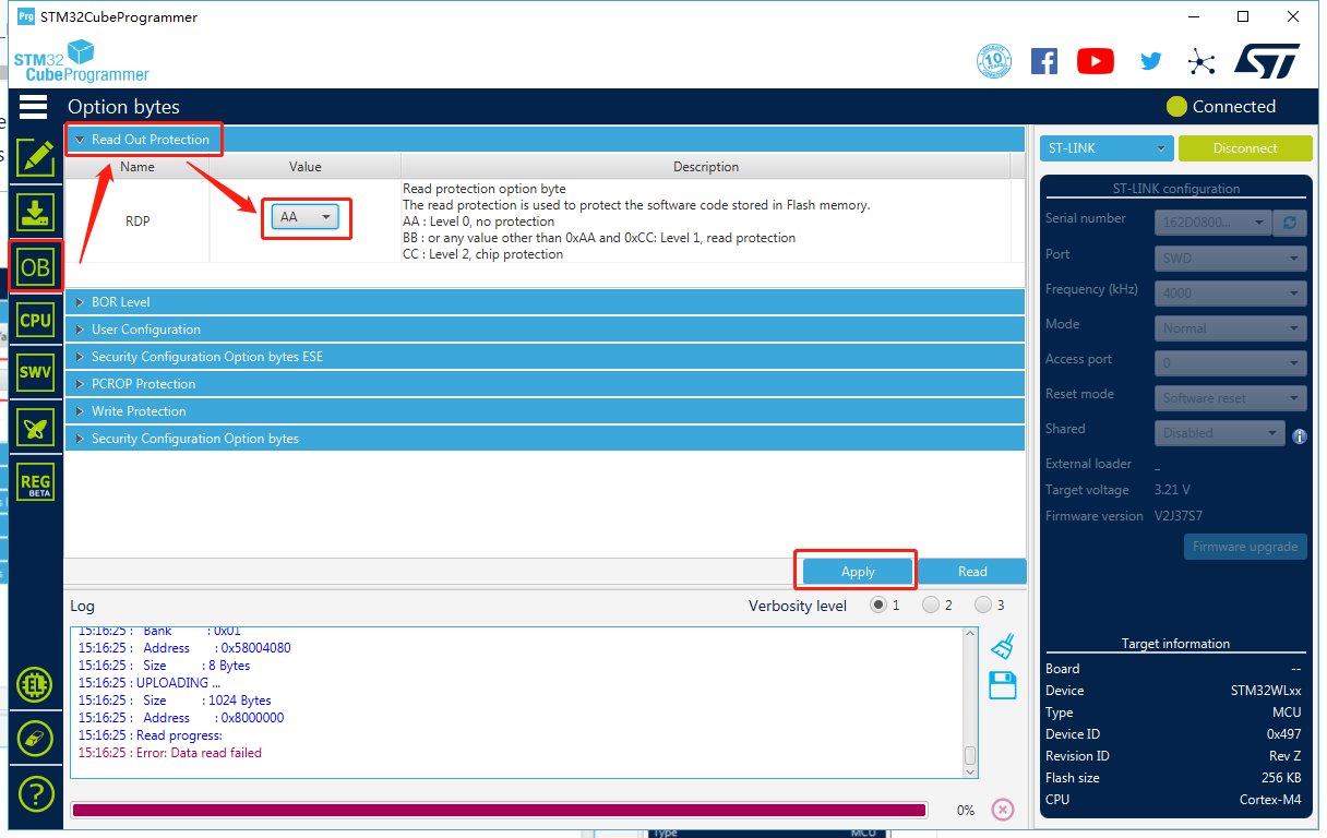
- Step 11. Make sure the Read Out Protection is
AA, if it is shown asBB, selectAAand clickApply:
- Step 12. Now, go to the
Erasing & Programmingpage, select your hex file path(for example:C:\Users\user\Downloads\LoRaWan-E5-Node\Projects\Applications\LoRaWAN\LoRaWAN_End_Node\STM32CubeIDE\Debug\LoRaWAN_End_Node.hex), select the programming options as the following picture, then clickStart Programming!
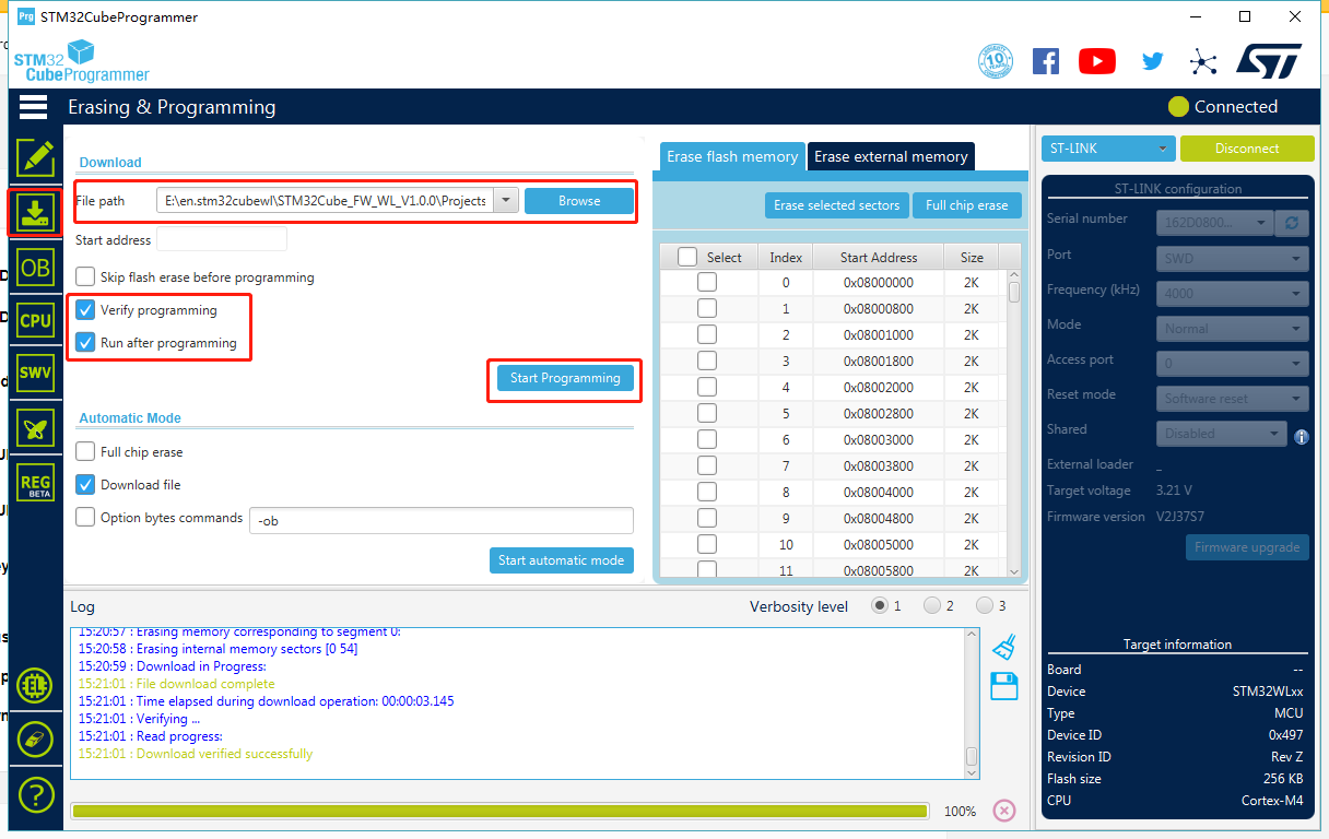
You will see the message Download verified successfully, once programming is finished.
- Step 13. If your LoRaWAN® Gateway and TTN are setup, Wio-E5 will join successfully after reset! A confirm LoRaWAN® package will be sent to TTN every 30 seconds. The following log will be printed on the serial monitor (Arduino Serial Monitor is used here) if the join is successful:

- Cheers! Now you have connected Wio-E5 to LoRaWAN® Network! You can now proceed to develop more exciting LoRaWAN® End Node applications!
Note: Wio-E5 only supports high power output mode, so you can't use these macro definitions in radio_board_if.h :
#define RBI_CONF_RFO     RBI_CONF_RFO_LP_HP
// or
#define RBI_CONF_RFO     RBI_CONF_RFO_LP
Eventhough RBI_CONF_RFO is defined as RBI_CONF_RFO_LP_HP in radio_board_if.h, it will not be used because USE_BSP_DRIVER is defined and BSP_RADIO_GetTxConfig() function returns RADIO_CONF_RFO_HP
FreeRTOS LoRaWAN®
This application will also connect Wio-E5 mini with TTN (The Things Network) and send data after connecting with a LoRaWAN® gateway. The difference between previous LoRaWAN® End Node application and this FreeRTOS LoRaWAN® application is that, the previous one runs on bare metal whereas this runs under FreeRTOS.
- Step 1. Click here to visit Seeed-Studio/LoRaWan-E5-Node repository and download it as a ZIP file
-
Step 2. Extract the ZIP file and navigate to
LoRaWan-E5-Node > Projects > Applications > FreeRTOS > FreeRTOS_LoRaWAN -
Step 3. Double click the .project file
-
Step 4. Refer to step 4 - step 13 from the previous LoRaWAN® End Node application to connect Wio-E5 mini with TTN!
FreeRTOS LoRaWAN® AT
This application will also connect Wio-E5 mini with TTN (The Things Network) and send data after connecting with a LoRaWAN® gateway. The difference between previous FreeRTOS LoRaWAN application and this application is that, you can use AT commands.
- Step 1. Click here to visit Seeed-Studio/LoRaWan-E5-Node repository and download it as a ZIP file
-
Step 2. Extract the ZIP file and navigate to
LoRaWan-E5-Node > Projects > Applications > FreeRTOS > FreeRTOS_LoRaWAN_AT -
Step 3. Double click the .project file
-
Step 4. Refer to step 4 - step 12 from the previous LoRaWAN End Node application
-
Step 5. Open a serial monitor such as Arduino Serial Monitor and you will see the following output

- Step 6. Type AT? and press ENTER to view all the available AT commands

-
Step 7. If you still want to change Device EUI, Application EUI, Application KEY and LoRawan® Region, you can change using AT commands. However, these parameters are already set in se-identity.h and lora_app.h in this example
-
Step 8. Type AT+JOIN=1 and you will see the following output once the join is successful!

Note: Here AT+JOIN=(Mode) format should be used. Mode corresponds to either 0 for ABP or 1 for OTAA
FreeRTOS LowPower
This application will enable low-power mode on Wio-E5 mini. Once the application is flashed, the board will consume power as normal for 2 seconds and enter low-power mode for 2 seconds and so on.
- Step 1. Click here to visit Seeed-Studio/LoRaWan-E5-Node repository and download it as a ZIP file
-
Step 2. Extract the ZIP file and navigate to
LoRaWan-E5-Node > Projects > Applications > FreeRTOS > FreeRTOS_LowPower -
Step 3. Double click the .project file
-
Step 4. Right click on the project and click Properties

- Step 5. Navigate to
C/C++ Build > Settings > MCU Post build outputs, tick Convert to Intel Hex file (-O ihex) and click Apply and Close

- Step 6. Click Build 'Debug', and it should compile without any errors


- Step 7. Open
STM32CubeProgrammer, connect ST-LINK to your PC, holdRESET Buttonof your Device, then clickConnectand releaseRESET Button:
- Step 8. Make sure the Read Out Protection is
AA, if it is shown asBB, selectAAand clickApply:
- Step 9. Now, go to the
Erasing & Programmingpage, select your hex file path(for example:C:\Users\user\Downloads\LoRaWan-E5-Node\Projects\Applications\FreeRTOS\FreeRTOS_LowPower\Debug\FreeRTOS_LowPower.hex), select the programming options as the following picture, then clickStart Programming!
You will see the message Download verified successfully, once programming is finished.
- Step 10. Connect the Wio-E5 mini to a PC by attaching a power meter. You will notice the red LED on the board blinks every second and the board switches between normal and low power states (The current on the power meter comes down for 1 second for lower power state and comes back up for 1 second for normal working state)

Low Power
This application will also enable low-power mode on Wio-E5 mini. The difference between previous FreeRTOS LowPower application and this Low Power application is that, the previous one runs under FreeRTOS whereas this runs on bare metal.
- Step 1. Click here to visit Seeed-Studio/LoRaWan-E5-Node repository and download it as a ZIP file
-
Step 2. Extract the ZIP file and navigate to
LoRaWan-E5-Node > Projects > Applications > LowPower -
Step 3. Double click the .project file
-
Step 4. Refer to step 4 - step 10 from the previous FreeRTOS LowPower application and you will see the same output at the end on the power meter!
Resources
Wio-E5 mini Datasheet:
Wio-E5 Datasheet:
Wio-E5 Certifications:
Relevant SDK:
Tech Support & Product Discussion
Please submit any technical issue into our forum.
Thank you for choosing our products! We are here to provide you with different support to ensure that your experience with our products is as smooth as possible. We offer several communication channels to cater to different preferences and needs.