ODYSSEY – STM32MP157C

The ODYSSEY – STM32MP157C is a single board computer that based on STM32MP157C, a dual-core Arm-Cortex-A7 core processor operating at 650Mhz. The processor also integrates an Arm Cortex-M4 coprocessor, which makes it suitable for real-time task. The ODYSSEY – STM32MP157C is created in a form of SoM(system on module) plus a Carrier board. The SoM has consisted of the MPU, PMIC, RAM and the carrier board is in Raspberry Pi form factor. The carries board includes all the necessary peripherals including Gigabytes Ethernet, WiFi/BLE, DC Power,USB Hosts, USB-C, MIPI-DSI, DVP for camera, audio, etc. With this board, customers can fast evaluate the SoM and deploy the SoM on their own carrier board easily and quickly.

Features
- Dual-core Arm-Cortex-A7 core processor with Cortex-M4 integrated
- SoM(system on module) includes MPU, PMIC, RAM.
- Raspberry Pi 40-Pin Compatible Carrier Board.
- Compact size and powerful
- open source hardware/SDK/API/BSP/OS
Specification
| Item | Values |
|---|---|
| Peripheral Interface | 2 x USB Host 1 x gigabit Ethernet interface 1 x 3.5mm audio interface 1 x MIPI DSI display interface 1 x DVP camera interface 2 x Grove (GPIO & I2C) 1 x SD card interface (on the back of the board) |
| WiFi/Bluetooth | WiFi 802.11 b/g/n 2.4GHz Bluetooth 4.1 |
| On-board LED | 1 x reset LED 3 x user-defined LED 1 x power LED |
| Power | 1 x DC interface (12V/2A power input is recommended) 1 x USB Type - C |
| Button | 1 x reset button 1 x user button 1 x dial code key |
| dimension | 56mm x 85mm |
| Operating temperature | 0 ~ 75 ℃ |
Application
- Industrial (CAN-Ethernet gateways etc )
- White goods(refrigerators,microwaves etc )
- Medical(data loggers etc)
- High-end wearables(VR device etc)
- Smart Home Devices
Hardware Overview
ODYSSEY – STM32MP157C consists of two parts: Carrier board and Seeed SoM - STM32MP157C.
Carrier board hardware details follow:


-
1.Carrier board : Install the Seeed SoM-STM32MP157C area, if the user wants to remove the core board, slowly tilt the core board up and then remove, never remove by hand.
-
2.DC Power Input Port : 12V~24V/2A (12V/2A power input is recommended)(5.5x2.1mm center-positive barrel).
-
3.ETH Interface : Network cable interface can be connected to gigabit level network.
-
4.USB Host: Two USB Host ports.
-
5.USB Device: USB 2.0 Type C. If Type C is used as board power input, a 5V/3A power adapter should be used.
-
6.Digital Grove Interface: Connect the Grove interface to the digital pin.
-
7.IIC Grove Interface: Connect the Grove interface to the IIC pin.
-
8.American Standard 3.5mm: Audio interface.
-
9.MIPI DSI Interface: Connect to a display with a MIPI DSI interface(FPC 20Pin 1.0mm).
-
10.40 PIN GPIO Interface: Compatible with Raspberry Pi's 40-PIN.
-
11.AP6236: 2.4G WiFi & BT 4.2 control chip.
-
12.Slide Switch: Can be used to select SD card or eMMC to start.
-
13.Debug UART: The system default debugging serial port can enter this serial port to access the system, we'll talk more about how to do that later.
-
14.JST 1.0mm: 3VRTC battery interface.
-
15.RST Key: system reset key.
-
16.PWR Button: Long press about 8S to shut down, short press to boot.
-
17.User Button: User programmable buttons.
-
18.PWR LED: Development board power led.
-
19.User LED: User programmable led.
-
20.ACA-5036-A2-CC-S: Onboard 2.4G ceramic antenna.
-
21.The IPEX 1 generation: External 2.4 G external antenna seat(When using an external antenna, need remove R49, R51 0Ω welding)
-
22. SD card slot: Is the area where a micro-sd card with the system is inserted.
-
23.DVP camera interface : Connect to camera with DVP interface (FPC 20Pin 1.0mm).
-
24.KSZ9031: 1000M Network cable drive network card.
-
25.STMPS2252MTR: Power switch chip.
-
26.MP9943: Buck DCDC Power chip.
-
27.WM8960: Audio codec chip.
-
28.MP2161: Buck DCDC Power chip.
Pin Function

ODYSSEY - STM32MP157C's 40-pin is fully compatible with Raspberry Pi's 40PIN, including GPIO, IIC, UART, SPI, IIS and PWM pins.
Introduction To Software
Preparatory Work
Materials Required
- ODYSSEY – STM32MP157C
- Wi-Fi network
- 4GB (or more memory) SD card and SD card reader
- PC or Mac
- USB To Uart Adapter (optional)
- 12V/2A DC interface adapter for power supply (optional)
- A USB type-c cable
Caution
Please plug the USB cable gently, otherwise you may damage the interface.Please use the USB cable with 4 wires inside, the 2 wires cable can't transfer data. If you are not sure about the wire you have, you can click here to buyMirror Installation
Like Raspberry Pi, you need to install the ODYSSEY – STM32MP157C image from your SD card to get it up and running. We offer two ways to start ODYSSEY – STM32MP157C. You can boot from an SD card or from eMMC.
A. Boot from SD card
-
Step 1. Select the firmware you want to download:
-
Step 2. Connect an SD card to a PC or MAC with an SD card reader, an SD card with more than 4G memory is required.
-
Step 3. Click here to download Etcher, then use the Etcher to write the
*.img.xzfile directly to the SD card. Or extract the*.img.xzfile into a*.imgfile, and then burn it to an SD card using another mirror write tool.
Click the plus icon to add the newly downloaded image file and the software will automatically select the SD card you inserted. Then click Flash! writing. It takes about 10 minutes to finish.

- Step 4. After writing the image to the SD card, insert the SD card into ODYSSEY – STM32MP157C. Use USB type-c port to power the Carrier board. Do not take out the SD card during writing. ODYSSEY – STM32MP157C will boot from the SD card, you can see the PWR and USER LED lighting on SOM. Now, go to the next section: the serial console.
Note
they mean to start up failed if the USER LED does not blink.Please check the boot switch whether it is SD_CARD.- Step 5. After writing the image to the SD card, insert the SD card into ODYSSEY – STM32MP157C. Use USB type-c port to power the Carrier board. Do not take out the SD card during writing. ODYSSEY – STM32MP157C will boot from the SD card, you can see the PWR and USER LED lighting on SOM. Now, go to the next section: the serial console.
B. Boot from eMMC
Note
If you want to Boot from eMMC, you have to access next section: the serial console first.-
Step 1. the process is the same as A. Boot from SD card if you first start up the ODYSSEY – STM32MP157C.
-
Step 2. Edit /boot/uEnv.txt to start eMMC boot then reboot.
sudo sh -c "echo cmdline=init=/opt/scripts/tools/eMMC/init-eMMC-flasher-v3-stm32mp1.sh >> /boot/uEnv.txt"
sudo reboot
-
Step 3. Wait for the USER LED bright continuously.that indicate the eMMC boot successfully if the USER LED bright continuously.
-
Step 4. Power off and unplug the SD card.
-
Step 5. Set the slide switch to EMMC and restart.
Serial Console
Now your ODYSSEY – STM32MP157C is up, you may want to access your Linux system through the console, then set up Network, and so on. A serial port access method is provided for Linux access:
- UART port - Used to debug low-level problems.(recommend)
Connect via UART port
In this section, we'll walk you through the use of the USB to TTL adapter, which connects to the ODYSSEY – STM32MP157C's Uart port(Located at the upper right of ODYSSEY – STM32MP157C), to establish a connection between your computer and ODYSSEY -STM32MP157C.

-
Step 1. Connect Uart port To PC/Mac using USB To TTL Adapter.If you don't have USB To TTL Adapter, click HERE to buy.(RX->TX,TX->RX)
-
Step 2. Using the following serial debugging tools, the baud rate is 115200:
- Windows : Use PUTTY, select
Serialprotocol, fill in the COM port corresponding to ODYSSEY -STM32MP157C,115200baud rate, 8 bit, no parity bits, a stop bit 1, no flow control. - Linux : Depending on the USB To TTL Adapter, should be
screen /dev/ttyACM0(,1, and so on) 115200orscreen /dev/ttyUSB0(,1, and so on) 115200. - Mac : Depending on the USB To TTL Adapter, should be
screen /dev/cu.usbserial1412(,1422, and so on) 115200orscreen /dev/cu.usbmodem1412(,1422, and so on) 115200.
- Windows : Use PUTTY, select
-
Step 3. The default user name is
debian, the password istemppwd -
Step 4. If you don't have USB to TTL Adapter, you can also use Arduino. If you use Arduino, connect one end of the jumper to the Arduino's RESET pin and the other end to the Arduino's GND pin. This will bypass your Arduino's ATMEGA MCU and turn your Arduino into a USB to TTL adapter. Please refer HERE Video tutorial. Now connect the GND pin of Arduino to the GND pin of ODYSSEY -STM32MP157C's Uart port. Connect Rx pins on Arduino to Rx pins on ODYSSEY -STM32MP157C's Uart port. Connect the Tx pin on the Arduino to the Tx pin on the ODYSSEY -STM32MP157C Uart port. Finally, connect the Arduino to the PC/Mac via the Arduino's USB cable. Now check to see if your PC/Mac has found your Arduino by typing the following command:
ls /dev/cu.usb* (Mac)
ls /dev/ttyACM* (Linux)
You should get feedback like this:
/dev/cu.usbmodem14XX where XX will vary depending on which USB port you used (on Mac)
/dev/ttyACMX where X will vary depending on which USB port you used  (on Linux)
Now follow the steps above to connect to ODYSSEY – STM32MP157C via a serial connection. This is usually what we need to do when we first boot up, as you will then set up ODYSSEY – STM32MP157C for Wi-Fi connection and then SSH connection.
Network Settings
A. Ethernet connection
You can connect to the network using an Ethernet cable. Just plug in the Ethernet cable to the Internet. Now, go to the next section: the Basic tool install.
B. Wi-Fi Settings
Note
If you want to using Wi-Fi, you have to access next section: Basic tool install first.- Step 1. Check the version of Linux kernel in the current environment and install the header file of kernel version.
sudo apt install linux-headers-$(uname -r) -y
- Step 2. Make and install driver of stm32p1 from
seeed-linux-dtverlaysin the GitHub.
git clone https://github.com/Seeed-Studio/seeed-linux-dtverlays
cd seeed-linux-dtverlays
make all_stm32mp1 CUSTOM_MOD_FILTER_OUT="jtsn-wm8960" && sudo make install_stm32mp1 CUSTOM_MOD_FILTER_OUT="jtsn-wm8960"
- Step 3. add dtbo package in
/boot/uEnv.txtto make it become effective after reboot.
sudo sh -c "echo uboot_overlay_addr0=/lib/firmware/stm32mp1-seeed-ap6236.dtbo >> /boot/uEnv.txt"
sudo reboot
- Step 4. Connect the wifi
Configure the ODYSSEY – STM32MP157C network through the network management tool connmanctl, which has been installed on the ODYSSEY -STM32MP157C image. Follow these instructions to easily complete the configuration.
robot@ev3dev:~$ sudo connmanctl
Error getting VPN connections: The name net.connman.vpn was not provided by any
connmanctl> enable wifi
Enabled wifi
connmanctl> scan wifi
Scan completed for wifi
connmanctl> services
*AO Wired                ethernet_b827ebbde13c_cable
                         wifi_e8de27077de3_hidden_managed_none
    AH04044914           wifi_e8de27077de3_41483034303434393134_managed_psk
    Frissie              wifi_e8de27077de3_46726973736965_managed_psk
    ruijgt gast          wifi_e8de27077de3_7275696a67742067617374_managed_psk
    schuur               wifi_e8de27077de3_736368757572_managed_psk
connmanctl> agent on
Agent registered
connmanctl> connect wifi_e8de27077de3_41      # You can use the TAB key at this point to autocomplete the name
connmanctl> connect wifi_e8de27077de3_41483034303434393134_managed_psk
Agent RequestInput wifi_e8de27077de3_41483034303434393134_managed_psk
  Passphrase = [ Type=psk, Requirement=mandatory ]
Passphrase? *************
Connected wifi_e8de27077de3_41483034303434393134_managed_psk
connmanctl> quit
Now use the following command to find ODYSSEY – STM32MP157C's IP address.
ifconfig
Basic tool install
1.SSH
SSH, short for Secure Shell, is formulated by the Network Working Group of IETF. SSH is a security protocol based on the application layer. SSH is a more reliable protocol that provides security for remote login sessions and other network services. There is no SSH protocol in the image provided by us, so we need to configure it through the serial port, so as to realize the communication between the device and the computer through SSH protocol. Enter the following command to install the SSH service in ODYSSEY -STM32MP157C.
sudo apt install ssh -y
Next, we'll use SSH to access ODYSSEY – STM32MP157C. Windows users can use third-party SSH clients. For Linux/Mac users, the SSH client is built in.
-
Windows users : Use PUTTY, select SSH protocol, fill in the correct IP address and click open. The user name is debian and the password is temppwd.
-
Linux/Mac users :
ssh debian@IP
// password: temppwd
Note
If the performance experience degrades while using SSH, please switch to a more accessible WiFi network.2.GIT
Git is a free and open source distributed version control system designed to handle everything from small to very large projects with speed and efficiency.
sudo apt install git -y
3.MAKE
sudo apt install make device-tree-compiler gcc -y
4.WGET
sudo apt install wget -y
Bluetooth Setting Up
- Step 1. Check the version of Linux kernel in the current environment and install the header file of kernel version.
sudo apt install linux-headers-$(uname -r) -y
- Step 2. Make and install driver of stm32p1 from
seeed-linux-dtverlaysin the GitHub.
git clone https://github.com/Seeed-Studio/seeed-linux-dtverlays
cd seeed-linux-dtverlays
make all_stm32mp1 CUSTOM_MOD_FILTER_OUT="jtsn-wm8960" && sudo make install_stm32mp1 CUSTOM_MOD_FILTER_OUT="jtsn-wm8960"
- Step 3. add dtbo package in
/boot/uEnv.txtto make it become effective after reboot.
sudo sh -c "echo uboot_overlay_addr0=/lib/firmware/stm32mp1-seeed-ap6236.dtbo >> /boot/uEnv.txt"
sudo reboot
Activate the bluetooth
Then activate the bluetooth by the command:
sudo apt -y install bluetooth bluez bluez-tools rfkill
systemctl is-enabled bluetooth.service
Connect the bluetooth
- Step 1. Scan the bluetooch by using bluetoothctl
the bluetoothctl is a tool that controls the Bluetooth to connect the other Bluetooth.
debian@npi:~$ bluetoothctl
[NEW] Controller 43:43:A0:12:1F:AC ReSpeaker-1FAC [default]
Agent registered
[bluetooth]# scan on
Discovery started
[CHG] Controller 43:43:A0:12:1F:AC Discovering: yes
[NEW] Device C8:69:CD:BB:9B:B3 C8-69-CD-BB-9B-B3
[NEW] Device E1:D9:68:0E:51:C0 MTKBTDEVICE
[NEW] Device 62:15:9C:3F:40:AA 62-15-9C-3F-40-AA
[NEW] Device 56:AF:DE:C0:34:25 56-AF-DE-C0-34-25
[NEW] Device B8:86:87:99:FB:10 SOLARRAIN
[CHG] Device B8:86:87:99:FB:10 Trusted: yes
[NEW] Device 04:5D:4B:81:35:84 MDR-1000X
[CHG] Device 04:5D:4B:81:35:84 Trusted: yes
[CHG] Device 4C:04:59:38:D3:25 ManufacturerData Key: 0x004c
[CHG] Device 4C:04:59:38:D3:25 ManufacturerData Value:
  10 05 0b 10 99 18 0a                             .......
[bluetooth]# scan off
[CHG] Device 04:5D:4B:81:35:84 RSSI is nil
[CHG] Device B8:86:87:99:FB:10 TxPower is nil
[CHG] Device B8:86:87:99:FB:10 RSSI is nil
[CHG] Device 4C:04:59:38:D3:25 RSSI is nil
[CHG] Device 58:44:98:93:35:24 RSSI is nil
Discovery stopped
[bluetooth]#
-
Step 2. Now using the command
pair + device IDto match bluetooth device with the ODYSSEY – STM32MP157C. -
Step 3. When you see the messega
Pairing successful, tapconnect + device ID.
[bluetooth]# pair 04:5D:4B:81:35:84
Attempting to pair with 04:5D:4B:81:35:84
[CHG] Device 04:5D:4B:81:35:84 Connected: yes
[CHG] Device 04:5D:4B:81:35:84 UUIDs: 00001108-0000-1000-8000-00805f9b34fb
[CHG] Device 04:5D:4B:81:35:84 UUIDs: 0000110b-0000-1000-8000-00805f9b34fb
[CHG] Device 04:5D:4B:81:35:84 UUIDs: 0000110c-0000-1000-8000-00805f9b34fb
[CHG] Device 04:5D:4B:81:35:84 UUIDs: 0000110e-0000-1000-8000-00805f9b34fb
[CHG] Device 04:5D:4B:81:35:84 UUIDs: 0000111e-0000-1000-8000-00805f9b34fb
[CHG] Device 04:5D:4B:81:35:84 ServicesResolved: yes
[CHG] Device 04:5D:4B:81:35:84 Paired: yes
Pairing successful
[CHG] Controller 43:43:A0:12:1F:AC Discoverable: no
[CHG] Device 04:5D:4B:81:35:84 ServicesResolved: no
[CHG] Device 04:5D:4B:81:35:84 Connected: no
[CHG] Controller 43:43:A0:12:1F:AC Discoverable: yes
[bluetooth]# connect 04:5D:4B:81:35:84
Attempting to connect to 04:5D:4B:81:35:84
[CHG] Device 04:5D:4B:81:35:84 Connected: yes
Connection successful
[CHG] Device 04:5D:4B:81:35:84 ServicesResolved: yes
[CHG] Controller 43:43:A0:12:1F:AC Discoverable: no
[MDR-1000X]#
If Connection successful pops up, configuration!
CANBUS Communication
The following is the process of CANBUS communication using 2 Channel CAN BUS FD Shield for Raspberry Pi based on ODYSSEY -- STM32MP157C, first use Seeeduino V4.2 to collect the environment temperature and humidity, and then through the Seeeduino V4.2 CAN - BUS shields V2 above and the ODYSSEY – STM32MP157C Channel 2 CAN BUS FD shields above for Raspberry Pi communication.
Preparation Work
Materials Required
- ODYSSEY - STM32MP157C
- Wi-Fi network
- 4GB (or more than 4GB) SD card and SD card reader
- PC or Mac
- USB To Uart Adapter(optional)
- 12V/2ADC interface adapter for power supply (optional)
- A USB type-c cable
- Two double-male dupont lines
- CAN-BUS Shield V2
- Seeeduino V4.2
- 2 Channel CAN BUS FD Shield for Raspberry Pi
- Grove - Light Sensor v1.2
- Grove - I2C High Accuracy Temp&Humi Sensor (SHT35)
Hardware Connection
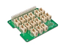
- Step 1. According to the installation guide insert 2 Channel CAN BUS FD Shield for Raspberry Pi onto ODYSSEY - STM32MP157C.
- Step 2. Insert CAN BUS Shield V2 into Seeeduino V4.2.
- Step 3. Connect Channel CAN BUS FD Shield for Raspberry Pi to can-bus Shield V2 using jumper wire.
| 2 Channel CAN BUS FD Shield for Raspberry Pi | CAN-BUS Shield V2 |
|---|---|
| CAN_0_L | CANL |
| CAN_0_H | CANH |
- Step 4. Power ODYSSEY STM32MP157C and Seeeduino V4.2
Dependency installation
- Step 1. Install the environment for
python.
sudo apt update
sudo apt install python3 python3-distutils python3-pyqt5  python3-pip python3-numpy -y
sudo pip3 install python-can pyqtgraph
- Step 2. Install
git.
sudo apt install git -y
- Step 3. Install the
makerelated environment.
sudo apt install make device-tree-compiler gcc -y
software installation
Install CAN-HAT and LCD drivers
- Step 1. Check the version of Linux kernel in the current environment and install the header file of kernel version.
sudo apt install linux-headers-$(uname -r) -y
- Step 2. Make and install driver of stm32p1 from
seeed-linux-dtverlaysin the GitHub.
git clone https://github.com/Seeed-Studio/seeed-linux-dtverlays
cd seeed-linux-dtverlays
make all_stm32mp1 CUSTOM_MOD_FILTER_OUT="jtsn-wm8960" && sudo make install_stm32mp1 CUSTOM_MOD_FILTER_OUT="jtsn-wm8960"
- Step 3. add dtbo package in
/boot/uEnv.txtto make it become effective after reboot.
sudo sh -c "echo uboot_overlay_addr7=/lib/firmware/stm32mp1-seeed-lcd-01.dtbo >> /boot/uEnv.txt"
sudo sh -c "echo uboot_overlay_addr8=/lib/firmware/stm32mp1-MCP2517FD-can0.dtbo >> /boot/uEnv.txt"
sudo reboot
- Step 4. Check the driver whether install successfully by using
dmesg, you will view the below information if it is successful.
debian@npi:~$ sudo insmod /lib/modules/$(uname -r)/extra/seeed/mcp25xxfd-can.ko
debian@npi:~$ dmesg | grep spi
[    1.057609] spi_stm32 44009000.spi: driver initialized
[    9.852726] mcp25xxfd spi0.0: Linked as a consumer to regulator.6
[    9.966510] mcp25xxfd spi0.0: MCP2517 successfully initialized.

debian@npi:~$ ifconfig -a
can0: flags=128<NOARP>  mtu 16
        unspec 00-00-00-00-00-00-00-00-00-00-00-00-00-00-00-00  txqueuelen 10  (UNSPEC)
        RX packets 0  bytes 0 (0.0 B)
        RX errors 0  dropped 0  overruns 0  frame 0
        TX packets 0  bytes 0 (0.0 B)
        TX errors 0  dropped 0 overruns 0  carrier 0  collisions 0
Config CAN-HAT and LCD
- Step 1. Configure
can-bus
sudo ip link set can0 up type can bitrate 500000 dbitrate 8000000 restart-ms 1000 berr-reporting on fd on
sudo ifconfig can0 txqueuelen 65536

debian@npi:~$ ip -details link show can0
3: can0: <NOARP,UP,LOWER_UP,ECHO> mtu 16 qdisc pfifo_fast state UNKNOWN mode DEFAULT group default qlen 10
    link/can  promiscuity 0 minmtu 0 maxmtu 0
    can state ERROR-ACTIVE (berr-counter tx 0 rx 0) restart-ms 0
          bitrate 500000 sample-point 0.875
          tq 25 prop-seg 34 phase-seg1 35 phase-seg2 10 sjw 1
          mcp25xxfd: tseg1 2..256 tseg2 1..128 sjw 1..128 brp 1..256 brp-inc 1
          mcp25xxfd: dtseg1 1..32 dtseg2 1..16 dsjw 1..16 dbrp 1..256 dbrp-inc 1
          clock 40000000numtxqueues 1 numrxqueues 1 gso_max_size 65536 /gso_max_segs 65535
- Step 2. Configure the
lcdenvironment
export QT_QPA_PLATFORM=linuxfb:fb=/dev/fb0
Run the Demo
Run the following code on 'ODYSSEY - STM32MP157C'
cd ~
git clone https://github.com/SeeedDocument/ODYSSEY-STM32MP157C.git
cd ~/ODYSSEY-STM32MP157C/examples
python3 QtViewerForStm32p1.py
Run CanBus_SendForArduino.ino on Seeeduino V4.2.

Play with GPIO
This part will introduce how to use grove.py to control GPIO and Grove Socket on ODYSSEY STM32MP157C.there exists two way to connect with the Grove Socket in this board. the one hand is using the Digital Grove Interface and IIC Grove Interface, the other is using ODYSSEY - STM32MP157C's 40-pin. The description of the PIN defines for the ODYSSEY - STM32MP157C's 40-pin please refer to [Pin Function](#Pin Function).It is convenient for you to use this ODYSSEY - STM32MP157C's 40-pin.So,Let's go.
Set to the gpio mode
- Step 1. Check the version of Linux kernel in the current environment and install the header file of kernel version.
sudo apt install linux-headers-$(uname -r) -y
- Step 2. Make and install driver of stm32p1 from
seeed-linux-dtverlaysin the GitHub.
git clone https://github.com/Seeed-Studio/seeed-linux-dtverlays
cd seeed-linux-dtverlays
make all_stm32mp1 CUSTOM_MOD_FILTER_OUT="jtsn-wm8960" && sudo make install_stm32mp1 CUSTOM_MOD_FILTER_OUT="jtsn-wm8960"
- Step 3. add dtbo package in
/boot/uEnv.txtto make it become effective after reboot.
sudo sh -c "echo uboot_overlay_addr1=/lib/firmware/stm32mp1-seeed-spi5.dtbo >> /boot/uEnv.txt"
sudo sh -c "echo uboot_overlay_addr2=/lib/firmware/stm32mp1-seeed-usart2.dtbo >> /boot/uEnv.txt"
sudo sh -c "echo uboot_overlay_addr3=/lib/firmware/stm32mp1-seeed-i2c4.dtbo >> /boot/uEnv.txt"
sudo reboot
- Step 4. Install the environment for
python3.
sudo apt install python3 python3-pip -y
Digital output on Basehat by using Grove.py
Hardware
- Step 1. Things used in this project:
| ODYSSEY – STM32MP157C | Grove - Buzzer | Grove Base Hat for Raspberry Pi |
|---|---|---|
 |  |  |
| Get ONE Now | Get ONE Now | Get ONE Now |
-
Step 2. Plug the Grove Base Hat into ODYSSEY - STM32MP157C.
-
Step 3. Connect the Grove Buzzer to D5 port of the Base Hat.
-
Step 4. Connect the ODYSSEY - STM32MP157C to PC through USB cable.
Software
- Step 1. Install the Grove.py
sudo pip3 install Seeed-grove.py
- Step 2. Download the source file by cloning the grove.py library.
cd ~
git clone https://github.com/Seeed-Studio/grove.py
- Step 3. Excute below command to run the code.
cd grove.py/grove
sudo python3 grove_gpio.py 5
Note
we will hear sound from the buzzer if everything has been well.Digital Input on Basehat by using Grove.py
Hardware
- Step 1. Things used in this project:
| ODYSSEY – STM32MP157C | Grove - Button | Grove Base Hat for Raspberry Pi |
|---|---|---|
|  | |
| Get ONE Now | Get ONE Now | Get ONE Now |
-
Step 2. Plug the Grove Base Hat into ODYSSEY - STM32MP157C.
-
Step 3. Connect the Grove Button to D5 port of the Base Hat.
-
Step 4. Connect the ODYSSEY - STM32MP157C to PC through USB cable.
Software
- Step 1. Install the Grove.py
sudo pip3 install Seeed-grove.py
- Step 2. Download the source file by cloning the grove.py library.
cd ~
git clone https://github.com/Seeed-Studio/grove.py
- Step 3. Excute below command to run the code.
cd grove.py/grove
sudo python3 grove_button.py 5
Note
we will view some information at the terminal if the button has been pressed.ADC on Basehat by using Grove.py
Hardware
- Step 1. Things used in this project:
| ODYSSEY – STM32MP157C | Grove - Temperature Sensor | Grove Base Hat for RasPi |
|---|---|---|
|  | |
| Get ONE Now | Get ONE Now | Get ONE Now |
-
Step 2. Plug the Grove Base Hat into ODYSSEY - STM32MP157C.
-
Step 3. Connect the temperature sensor to port A0 of the Base Hat.
-
Step 4. Connect the ODYSSEY - STM32MP157C to PC through USB cable.
Software
- Step 1. Install the Grove.py
sudo pip3 install Seeed-grove.py
- Step 2. Download the source file by cloning the grove.py library.
cd ~
git clone https://github.com/Seeed-Studio/grove.py
- Step 3. Excute below command to run the code.
cd grove.py/grove
sudo python3 grove_temperature_sensor.py 0
Note
we will view temperature data at the terminal if everything has been well.UART on Basehat by using Grove.py
Hardware
- Step 1. Things used in this project:
| ODYSSEY – STM32MP157C | Grove Base Hat for RasPi |
|---|---|
|  |
| Get ONE Now | Get ONE Now |
-
Step 2. Plug the Grove Base Hat into ODYSSEY - STM32MP157C.
-
Step 3. Connect RX To TX in Basehat using jumper
-
Step 4. Connect the ODYSSEY - STM32MP157C to PC through USB cable.
Software
- Step 1. Install the Grove.py
sudo pip3 install Seeed-grove.py
- Step 2. Download the source file by cloning the grove.py library.
cd ~
git clone https://github.com/Seeed-Studio/grove.py
- Step 3. Excute below command to run the code.
cd grove.py/grove
python uart.py
if we connect the TX to RX we will get hello seeder at terminal.and the location of TX and RX we can view Pin Function.
I2S on ODYSSEY-STM32MP157C
In this section, we will explain the control principle of the Linux I2S programming. Now we will use I2S and ReSpeaker 2-Mics Pi HAT to tell you how to use it.
Hardware
- Step 1. Things used in this project:
| ODYSSEY – STM32MP157C | ReSpeaker 2-Mics Pi HAT |
|---|---|
|  |
| Get ONE Now | Get ONE Now |
- Step 2. According to the installation hardware guide insert ReSpeaker 2-Mics Pi HAT onto ODYSSEY – STM32MP157C.
Software
- Step 1. Install alsa-utils by using
apt
sudo apt install alsa-utils -y
- Step 2. Go to the dtbs file location and download the stm32mp1 dtb file.
debian@npi:~$ cd /boot/dtbs/4.19.9-stm32-r1/
debian@npi:/boot/dtbs/4.19.9-stm32-r1$ sudo wget https://files.seeedstudio.com/wiki/ODYSSEY-STM32MP157C/res/stm32mp1-seeed-npi-full-rpi-exp.dtb
Note: You can also download the stm32mp1 .dtb file here
- Step 3. Config the
uEnv.txtas following:
debian@npi:~$ sudo vi /boot/uEnv.txt
Change the dtb settings to
dtb=stm32mp1-seeed-npi-full-rpi-exp.dtb
- Step 4. reboot
sudo reboot
- Step 5. Go into the
seeed-linux-dtverleysfolder and configure soundstate as follow:
debian@npi:~$ cd ~/seeed-linux-dtverlays/
debian@npi:~/seeed-linux-dtverlays$ sudo cp extras/wm8960_asound-stm32mp1 /var/lib/alsa/asound.state
debian@npi:~/seeed-linux-dtverlays$ sudo alsactl restore
- Step 6. Check the driver whether install successfully by using
aplayandarecord, you will view the below information if it is successful.
debian@npi:~/seeed-linux-dtverlays$ aplay -l
**** List of PLAYBACK Hardware Devices ****
card 0: seeed2micvoicec [seeed-2mic-voicecard], device 0: 4000b000.audio-controller-wm8960-hifi wm8960-hifi-0 []
  Subdevices: 1/1
  Subdevice #0: subdevice #0
card 1: STM32MP1SEEEDNP [STM32MP1-SEEEDNPi], device 0: 4400b004.audio-controller-wm8960-hifi0 wm8960-hifi0-0 []
  Subdevices: 1/1
  Subdevice #0: subdevice #0
debian@npi:~/seeed-linux-dtverlays$ arecord -l
**** List of CAPTURE Hardware Devices ****
card 0: seeed2micvoicec [seeed-2mic-voicecard], device 0: 4000b000.audio-controller-wm8960-hifi wm8960-hifi-0 []
  Subdevices: 1/1
  Subdevice #0: subdevice #0
card 1: STM32MP1SEEEDNP [STM32MP1-SEEEDNPi], device 1: 4400b024.audio-controller-wm8960-hifi1 wm8960-hifi1-1 []
  Subdevices: 1/1
  Subdevice #0: subdevice #0
- Step 7. Now you can start playing with ReSpeaker 2-Mics Pi Hat! For simple record and play testing, run the following command:
- To record an audio to
test.wav:
arecord -f cd -r 48000 -Dhw:0 test.wav
- To play the
test.wavaudio. Remember to plug in a headphone or speaker to output the audio.
aplay -Dhw:0 -r 48000 test.wav
Note
if you cannot get any sound maybe you can reboot again.For more information about the ReSpeaker 2-Mics Pi HAT you can visit wiki
Resourses
- [PDF] STM32MP157C Datasheet
- [SCH] Seeed SoM - STM32MP157C
- [SCH] ODYSSEY-STM32MP157C
- [3Dfile] ODYSSEY-STM32MP157C
- [OrCAD] ODYSSEY-STM32MP157C
- [OrCAD] Seeed SoM - STM32MP157C
- [PDF] ODYSSEY-STM32MP157C 2d file
- [PDF] STM32 Reference Guide
- [URL] Advanced system development
ODYSSEY-STM32MP157C Advanced system development
- Availability
- Vendor Documentation
- Basic Requirements
- ARM Cross Compiler: GCC
- Bootloader: U-Boot
- Linux Kernel
- Root File System
- Setup microSD card
- Install Kernel and Root File System
- Copy Root File System
- Set uname_r in /boot/uEnv.txt
- Device Tree Binary
- Copy Kernel Image
- Copy Kernel Device Tree Binaries
- Copy Kernel Modules
- File Systems Table (/etc/fstab)
- Remove microSD/SD card
- Comments
Tech Support & Product Discussion
Thank you for choosing our products! We are here to provide you with different support to ensure that your experience with our products is as smooth as possible. We offer several communication channels to cater to different preferences and needs.