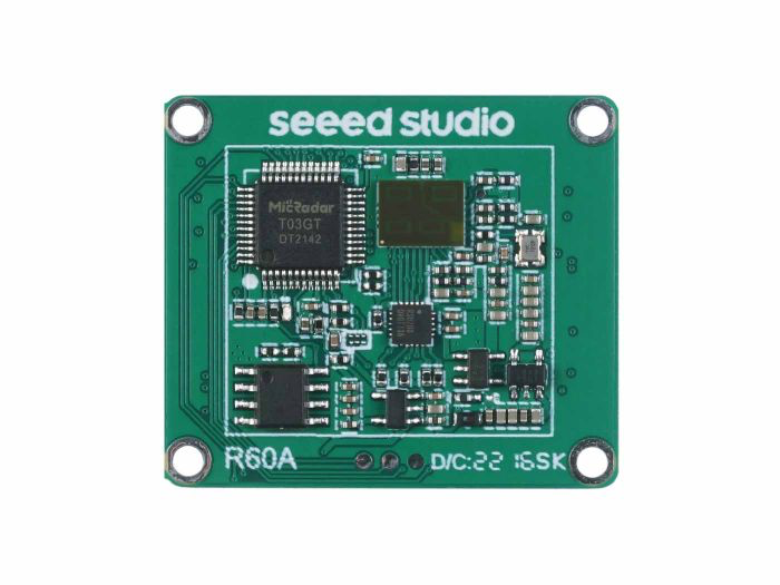
60GHz mmWave Sensor - Fall Detection Module Pro (MR60FDA1)
Introduction
60GHz mmWave Radar Sensor - Fall Detection Module Pro applies FMCW detected theory to implement simultaneous human activities detection including moving, falling, and stationary in high accuracy, providing a fully total private and secure environment, independently from other noisy influences. It is a standard biotic radar system in private property surveillance, falling caution, elderly health care, performing well in home, hotel, as well as hospital. In this wiki, we will introduce you how to utilize it.
Application
- Smart home
- Health care
- Fall detection
- Smart hotel
- Medical assistants
Feature
- Enabled theory: Implement radar detection based on 60GHz FM continuous wave signals
- Enhanced detecting algorithm: Sense and output simultaneously human activities including moving, falling, and stationary in the self-adaption environment
- Perfect privacy protection: Apply FMCW monitoring technology to provide surveillance capabilities without identification
- Health-friendly working status: Output power as low as harmless to the human body
- High stability: Independ from temperature, humidity, noise, airflow, dust, light, and other environmental influences
- High measured accuracy: Achieve fall detection accuracy up to 90% and achieve presence awareness function accuracy up to 90 %
- High flexibility hardware design radar: Support secondary development, adapt to various scenarios applications
Specification
| Detection angle and distance | Minimum | Typical | Maximum | Unit |
|---|---|---|---|---|
| Content Minimum Typical Maximum Units | ||||
| Radius of movement of people detection [1] | 6 | metre | ||
| Fall monitoring radius [2] | 3 | metre | ||
| Radar detection angle (horizontal) | 60 | degree | ||
| Radar detection angle (pitch) | 60 | degree | ||
| Note: [1][2] Radar hang height 2.8 m, radius of radar projection. | ||||
| Electrical characteristics | ||||
| Operating voltage (VCC) | 4.5 | 5 | 6 | V |
| Operating current (ICC) | 90 | 93 | 100 | mA |
| Operating temperature (TOP) | -20 | 60 | ℃ | |
| Storage temperature (TST) | -40 | 80 | ℃ | |
| RF performance | ||||
| Operating frequency (fTX) | 58 | 63.5 | GHz | |
| Transmitted power (Pout) | 6 | dBm |
Hardware Overview
Before everything starts, it is quite essential to have some basic parameters of the product. The following table provides information about the characteristics of 60GHz mmWave Sensor - Fall Detection Pro Module.
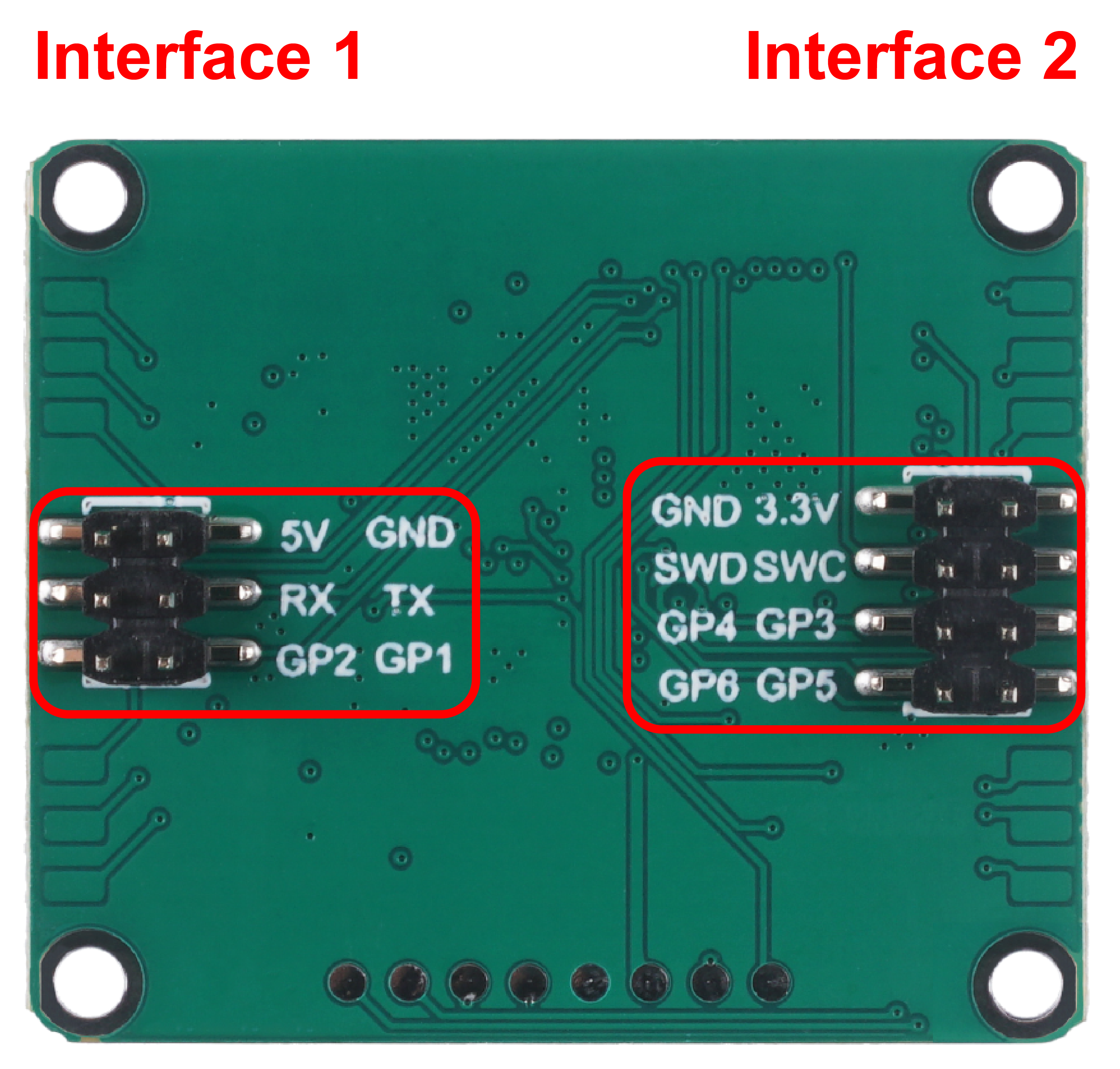
- Interface 1:
- The 5V pin is the power supply interface for the sensor.
- RX and TX are the data transmission interfaces for the sensor. RX means serial receive and TX means serial transmit.
- The human presence status output interface. You can use the level of these two pins to determine the current human movement in the environment.
- GP2 output: high level - occupied, low level - unoccupied.
- GP1 output: high level - active, low level - stationary.
- Interface 2:
- Flash firmware pinout: GND/3.3V/SWD/SWC.
- Overhead input/output pins: GP3~GP6.
Getting Started
Firmware Version Updates
The mmwave sensor has undergone a long period of technical precipitation and valuable suggestions provided by users, and we have been iterating on the original product to provide more accurate and reliable monitoring results and a better experience for our users.
Newly shipped sensors are shipped with the latest firmware by default to ensure the latest product experience. However, for the sake of the old user experience, we hereby provide the latest firmware and update method to ensure that you can use our latest technology.
Universal method - use J-link to burn firmware
If you encounter the wrong firmware or radar anomaly, firmware malfunction, etc., using this method to re-flash the firmware is the most effective way.
Download of the latest firmware
| Firmware Version | Download Address |
|---|---|
| Jlink_MR60FDA1-V0821.bin | Download |
| Jlink_MR60FDA1-V0728.bin | Download |
| Jlink_MR60FDA1-V114.bin | Download |
-
Please check the function of your product carefully, please do not mix with other mmwave sensors to brush this firmware, otherwise it may cause abnormal product function, the consequences need to be your own responsibility!
-
Please also note that different ways of updating the firmware use different firmware content, what you are downloading is the firmware burned via J-link.
To update your radar to the latest version
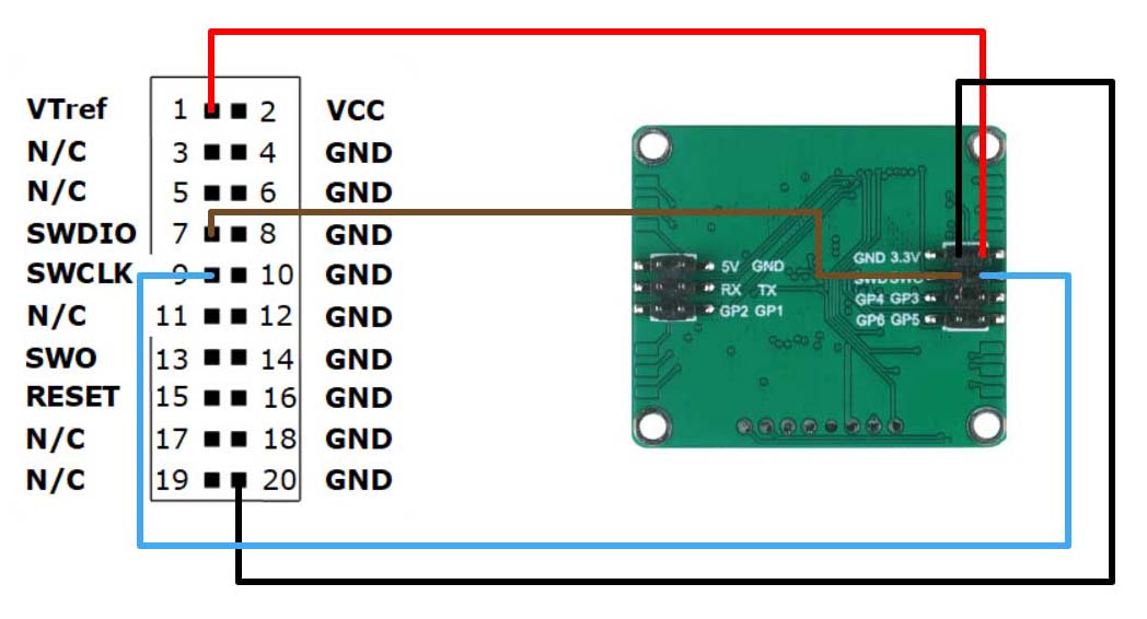
Step1. You will need to have a Jlink and MR60FDA1 60GHz mmWave Sensor.
Connect the radar and Jlink together via Dupont wire as shown in the diagram below.
Step2. Download the necessary software and firmware.
| File | Download Address |
|---|---|
| JlinkV644e.rar | Download |
| Pack_Segger_AT32F4xx_v1.3.3.zip | Download |
Step3. Unzip JlinkV644e.rar and open the JLink_Windows_V644e.exe file inside.
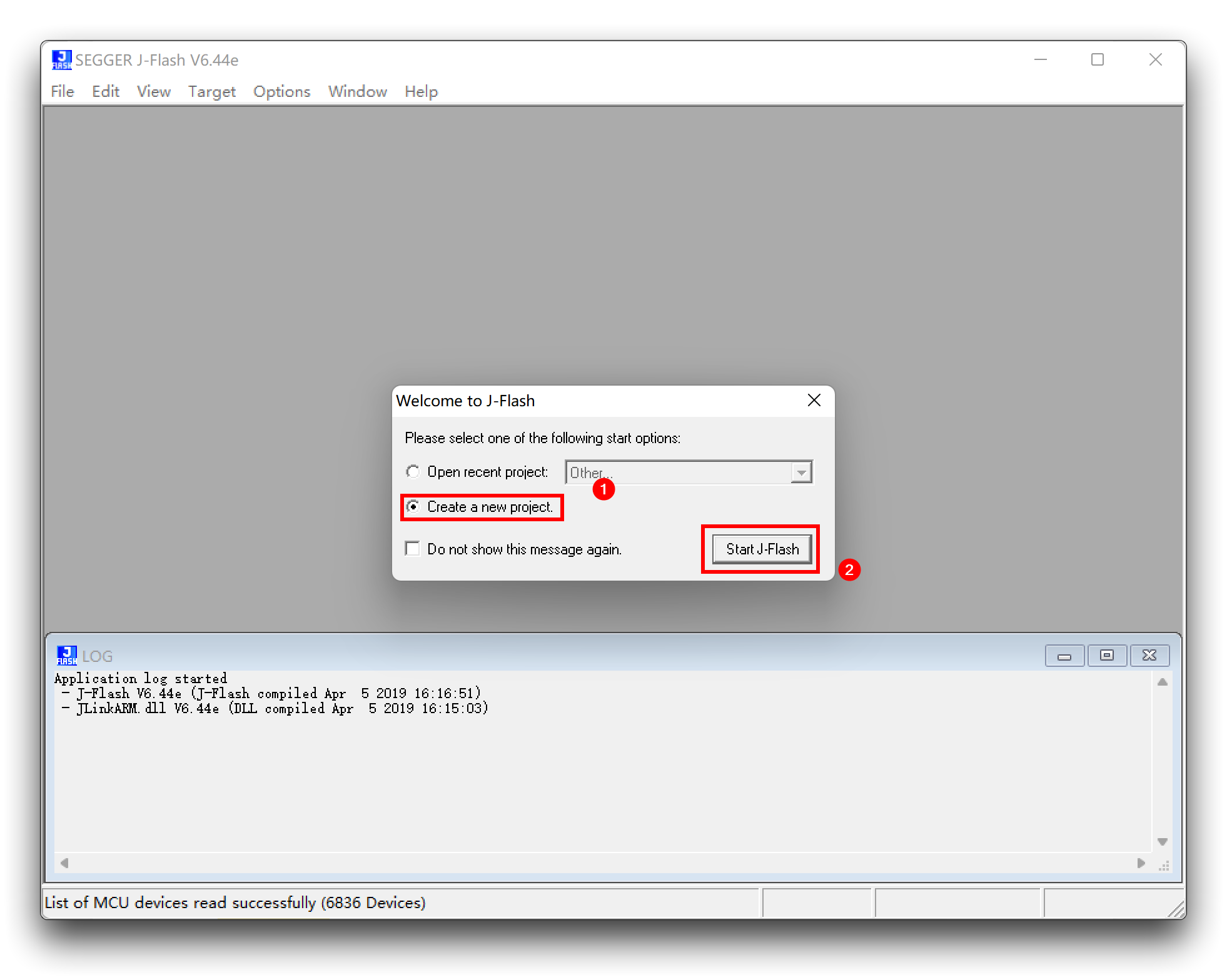
Just follow the default options to install. Once the installation is complete, start the J-Flash V6.44e software.
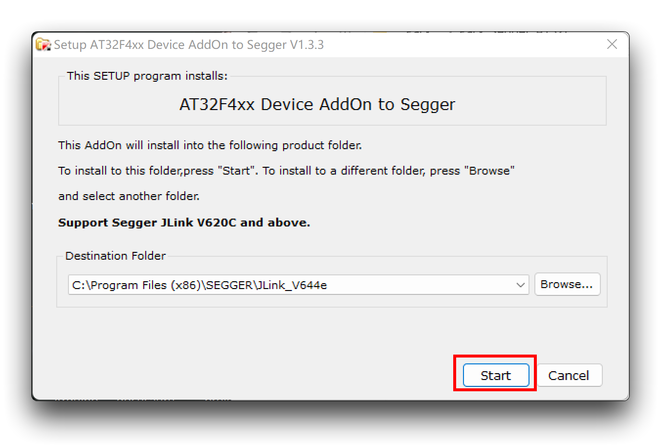
Step4. Install the chip package.
Unzip Pack_Segger_AT32F4xx_v1.3.3.zip and open Segger_AT32F4xx_AddOn.exe inside.
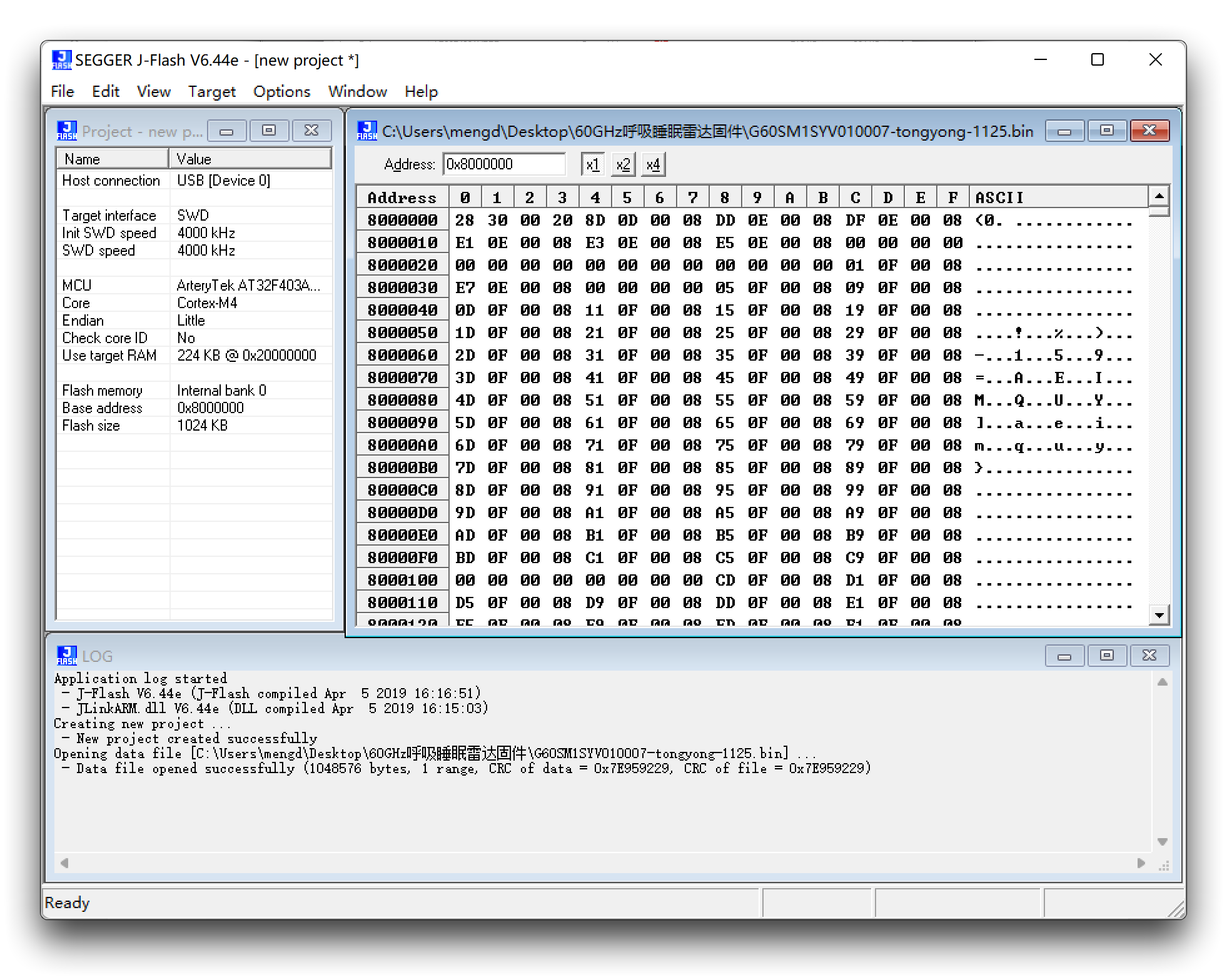
Step5. Create a new project.
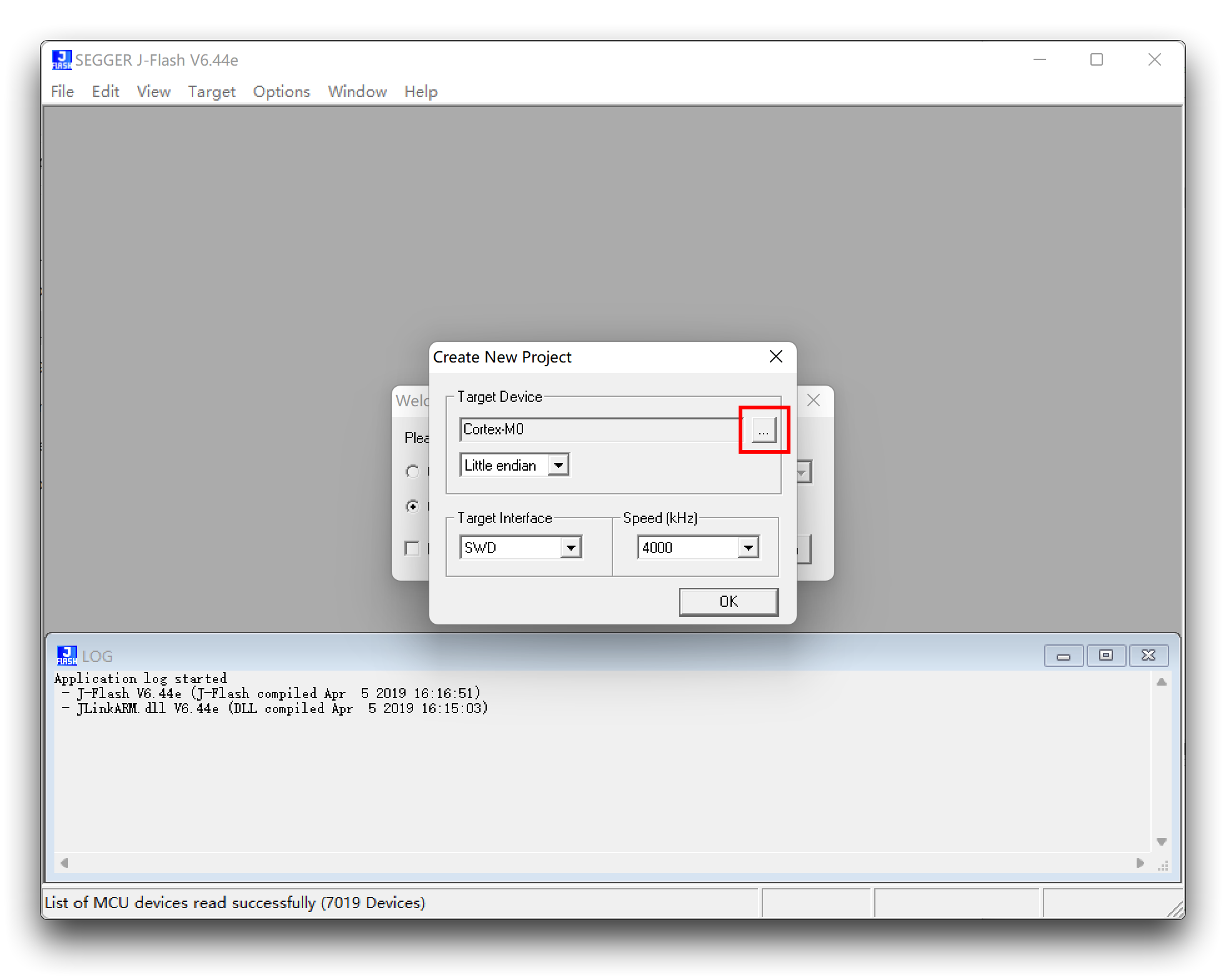
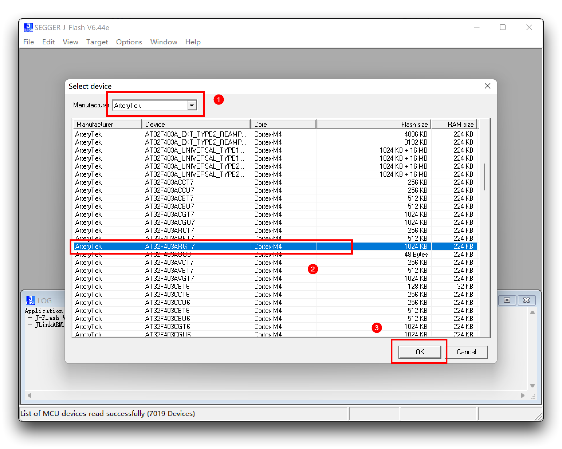
Find and choose AT32F403ARGT7.
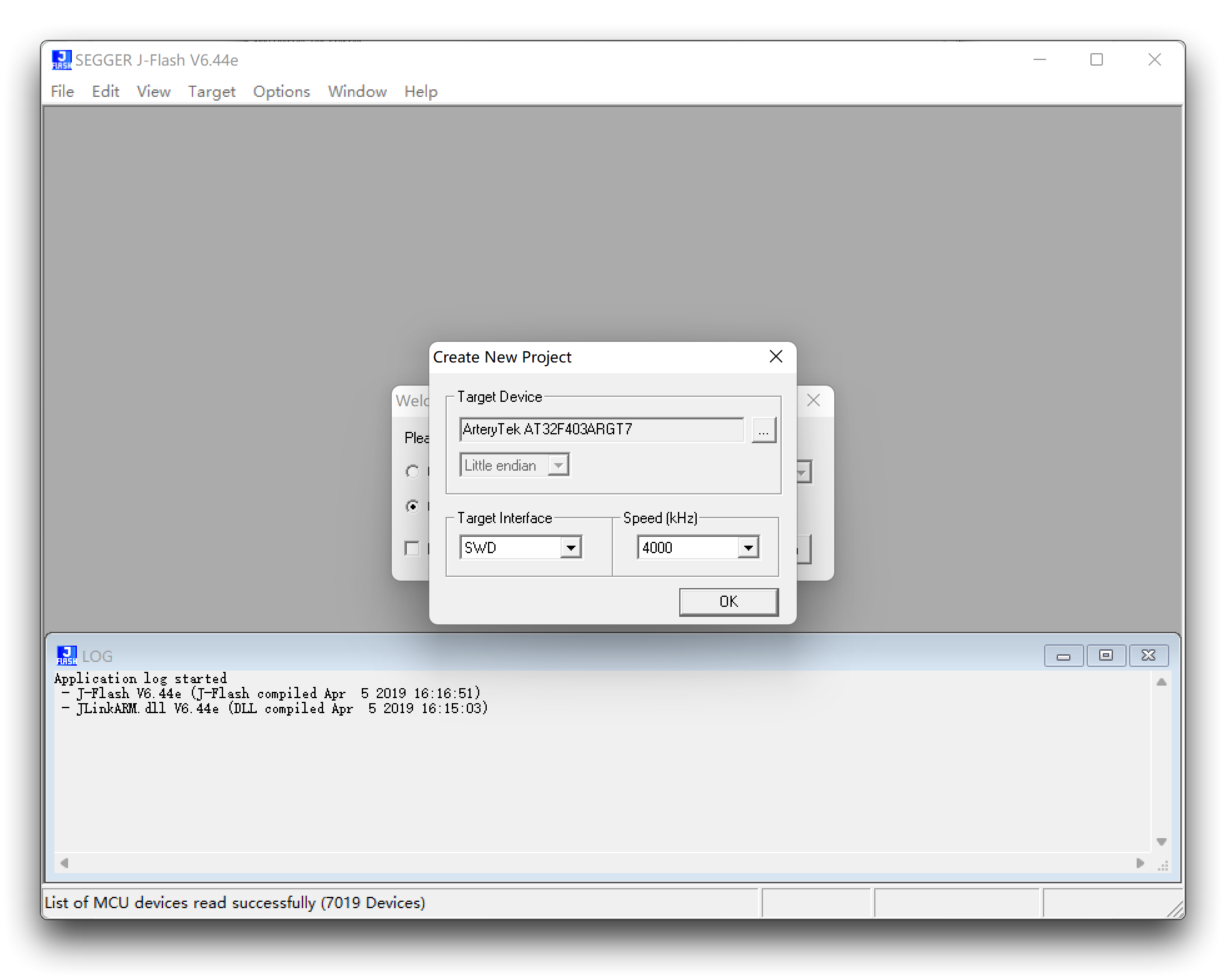
Step6. Drag and drop the radar firmware (.bin file) into this software and a window will pop up, we will just use its default starting address of 0x8000000.
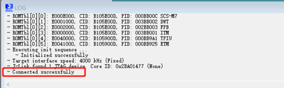
Step7. Clink Target -> Connect
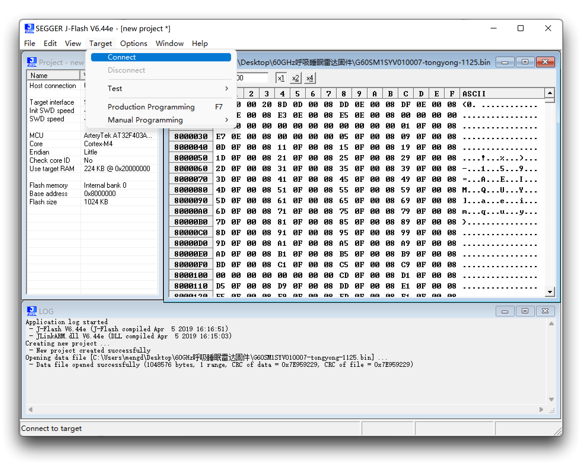
When the connection is successful it will show Connected successfully.
Erase firmware: Target -> manual Programming -> Erase Chip
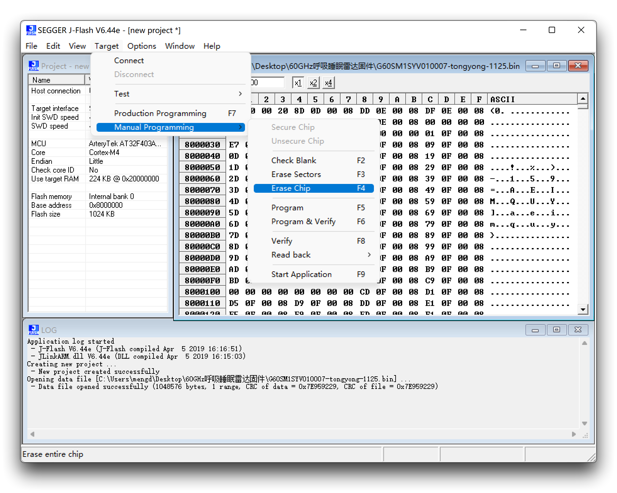
Upgrade firmware: Target -> manual Programming -> Program & Verify
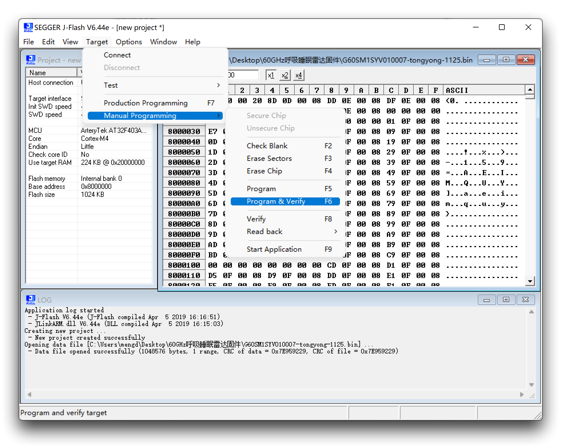
At this point, the firmware update is complete.
Update firmware via UART
Considering that J-link is expensive, it is too extravagant to buy a J-link for the vast majority of users who only need to update their radar firmware, so we offer an update method via UART.
Download of the latest firmware
| Firmware Version | Download Address |
|---|---|
| UART_MR60FDA1-230821.bin | Download |
| UART_MR60FDA1-230728.bin | Download |
| UART_MR60FDA1-230227.bin | Download |
| UART_MR60FDA1-230915.bin | Download |
-
Please check the function of your product carefully, please do not mix with other mmwave sensors to brush this firmware, otherwise it may cause abnormal product function, the consequences need to be your own responsibility!
-
Please also note that different ways of updating the firmware use different firmware content, what you are downloading is the firmware burned via UART.
-
Make sure your radar firmware version is at least version G60FD1SYv010102 before using the UART to upgrade the firmware, otherwise it may disable the radar, at which point you'll have to use J-link to burn the firmware to use it!
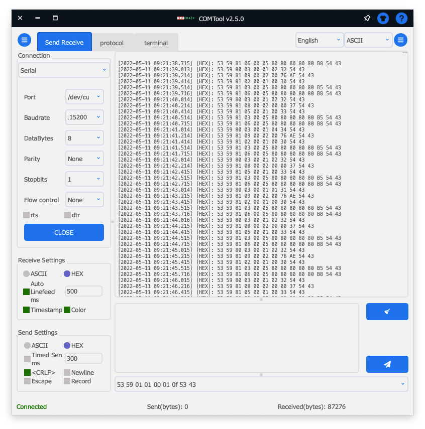
You can query the firmware version number information by sending the command 0x53 0x59 0x02 0xA4 0x00 0x01 0x0F 0x62 0x54 0x43 to Radar. The data reported by the radar is then displayed as a string, and you will see an effect similar to the one shown below.
G60FD1SYv010104 is the model number reported on the radar, where 010104 is the version number. This means that this sensor supports UART upgrade.

To update your radar to the latest version
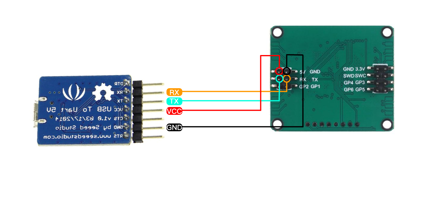
Step 1. You will need to have a UART to USB and MR60FDA1 60GHz mmWave Sensor.
Connect the radar and UART to USB together via Dupont wire as shown in the diagram below.
Step 2. Download the necessary software and firmware.
| File | Download Address |
|---|---|
| PackageMake-v1.1.1.zip | Download |
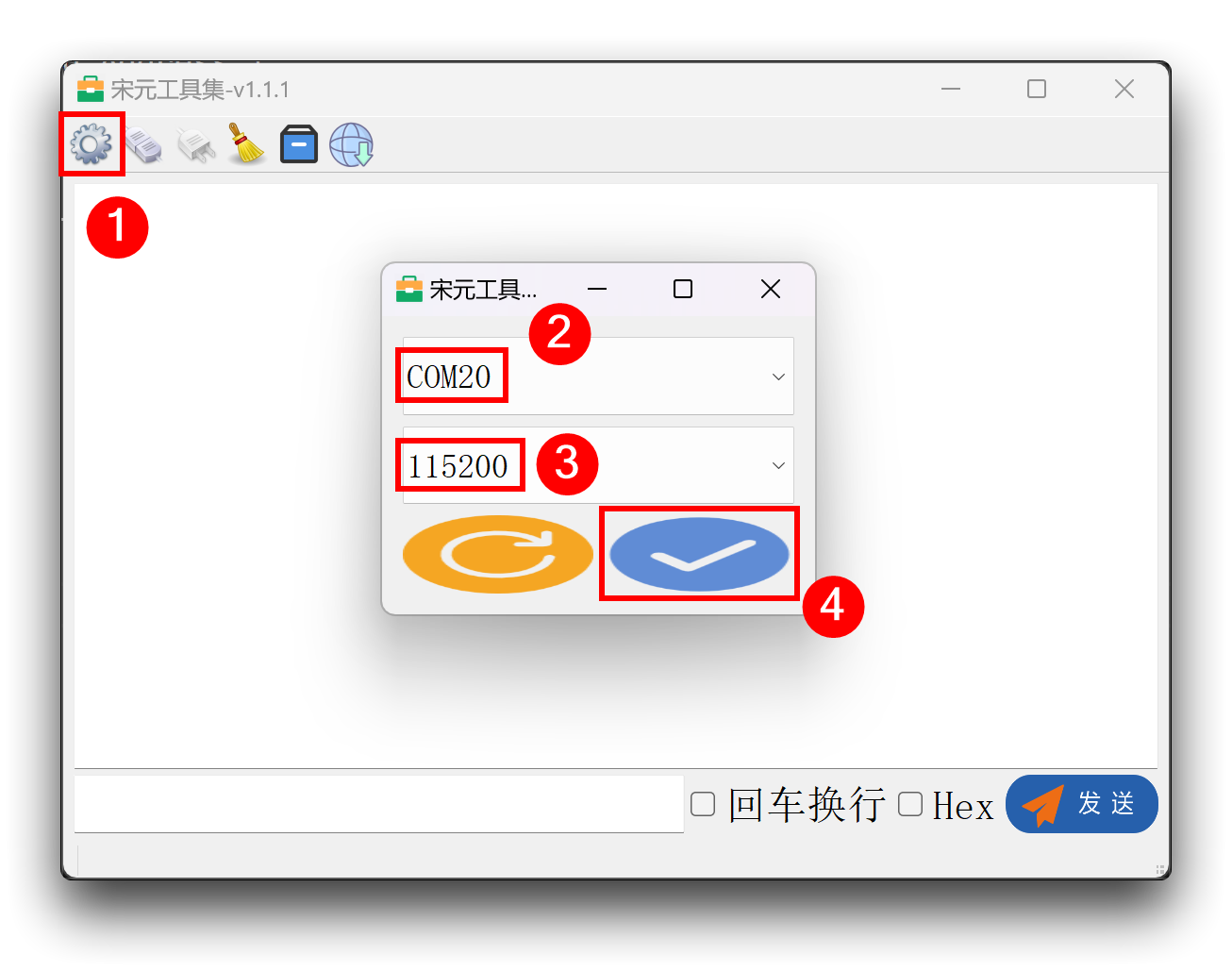
Step 3. Unzip the package PackageMake-v1.1.1.zip and open the PackageMake-v1.1.1.exe file inside.
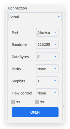
Connect the UART to USB with the sensor connected to the computer, click the gear pattern in the upper left corner of the software, select the port number, set the baud rate to 115200, and then click the bottom right corner to confirm. (If the port number is not found, check the connection and then click the refresh button in the lower left corner to retry)
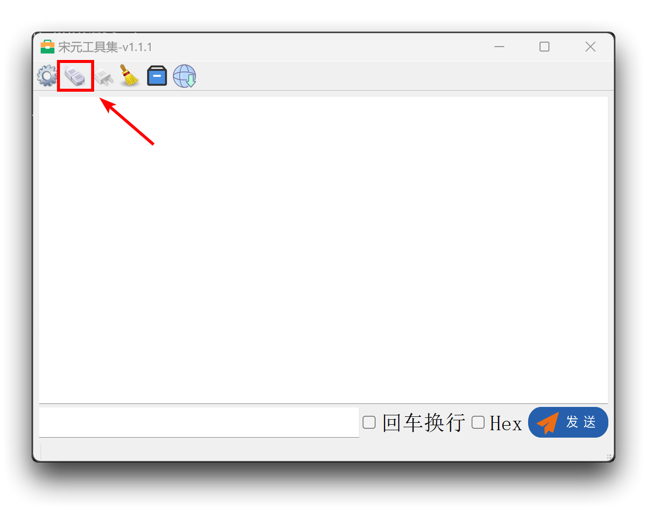
Step 4. Connecting the sensor
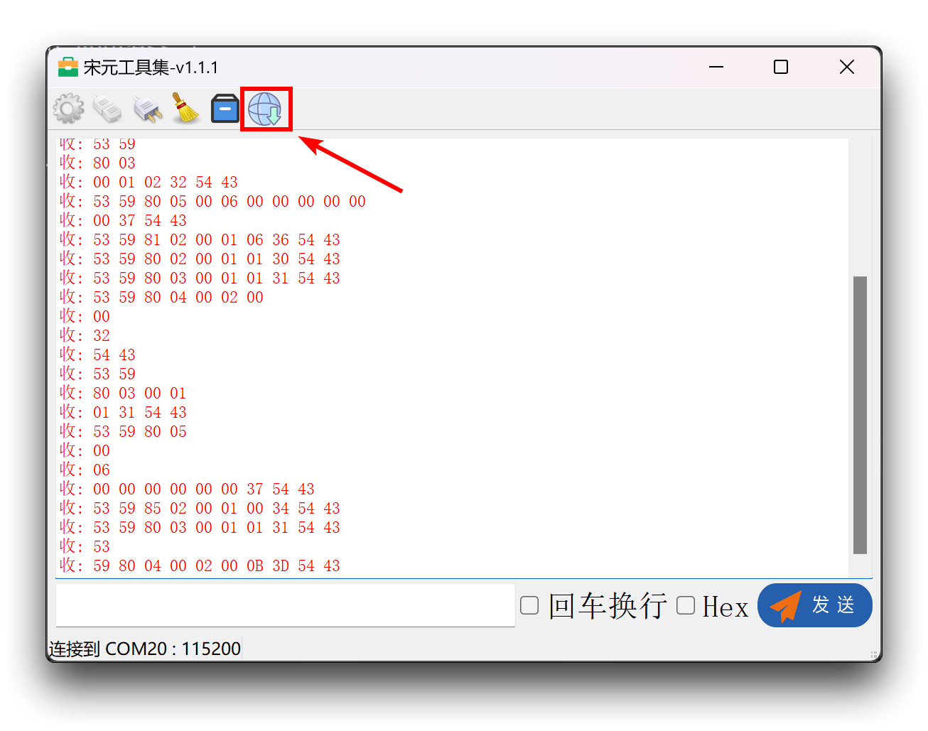
After you have finished setting up the serial port as described above, click on the second icon in the upper right corner and you will see the raw data from the radar printed out if the port is selected correctly.
Step 5. Update firmware
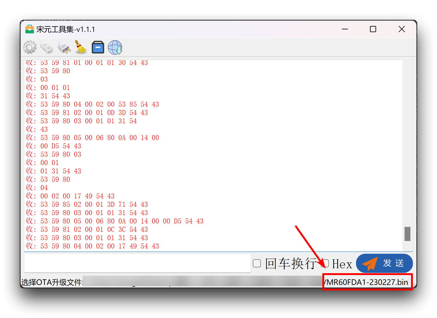
Click the last icon in the upper right corner of the left mouse button, this will bring up a window to select the firmware. Please select the firmware version you have downloaded.
After the selection is complete, the selected file path will appear under the software, please double check if the selected firmware version and model is consistent with the sensor you are using.
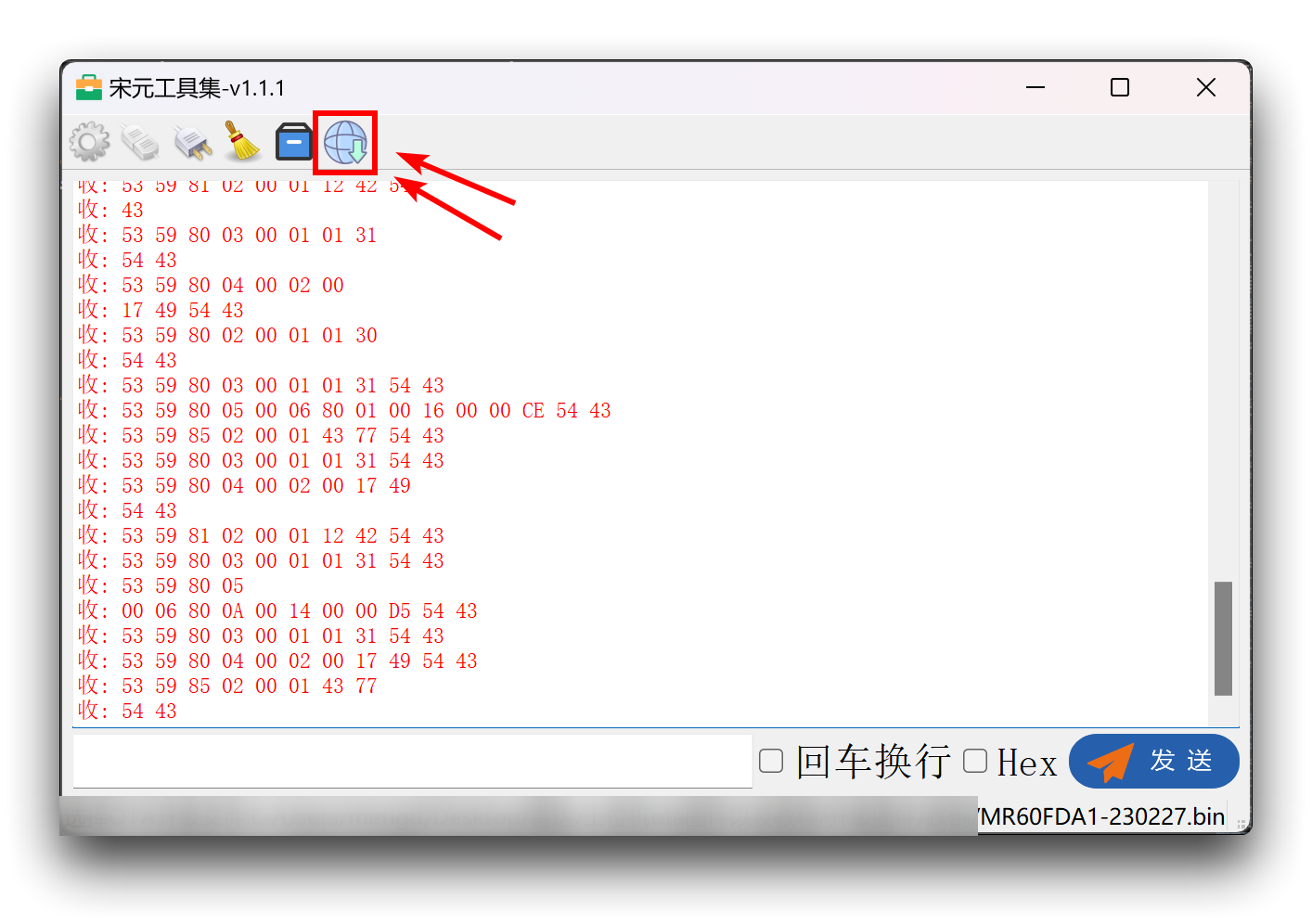
To upgrade the firmware, please double click the left mouse button to the last image on the top left of the software, then the firmware will start downloading to the sensor.
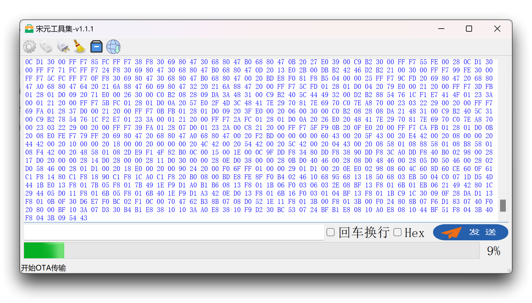
Wait for the progress bar to finish and the firmware update is complete.
Use of the upper computer
Connect the sensor directly to the computer's usb port via a UART to USB device. The wiring is shown in the table below.
| |||
| UART to USB | MR60FDA1 Sensor | ||
| 5V | --> | 5V | |
| GND | --> | GND | |
| RX | --> | TX | |
| TX | --> | RX | |
In addition to the serial software mentioned above, you can also use the upper computer software designed for radar directly.
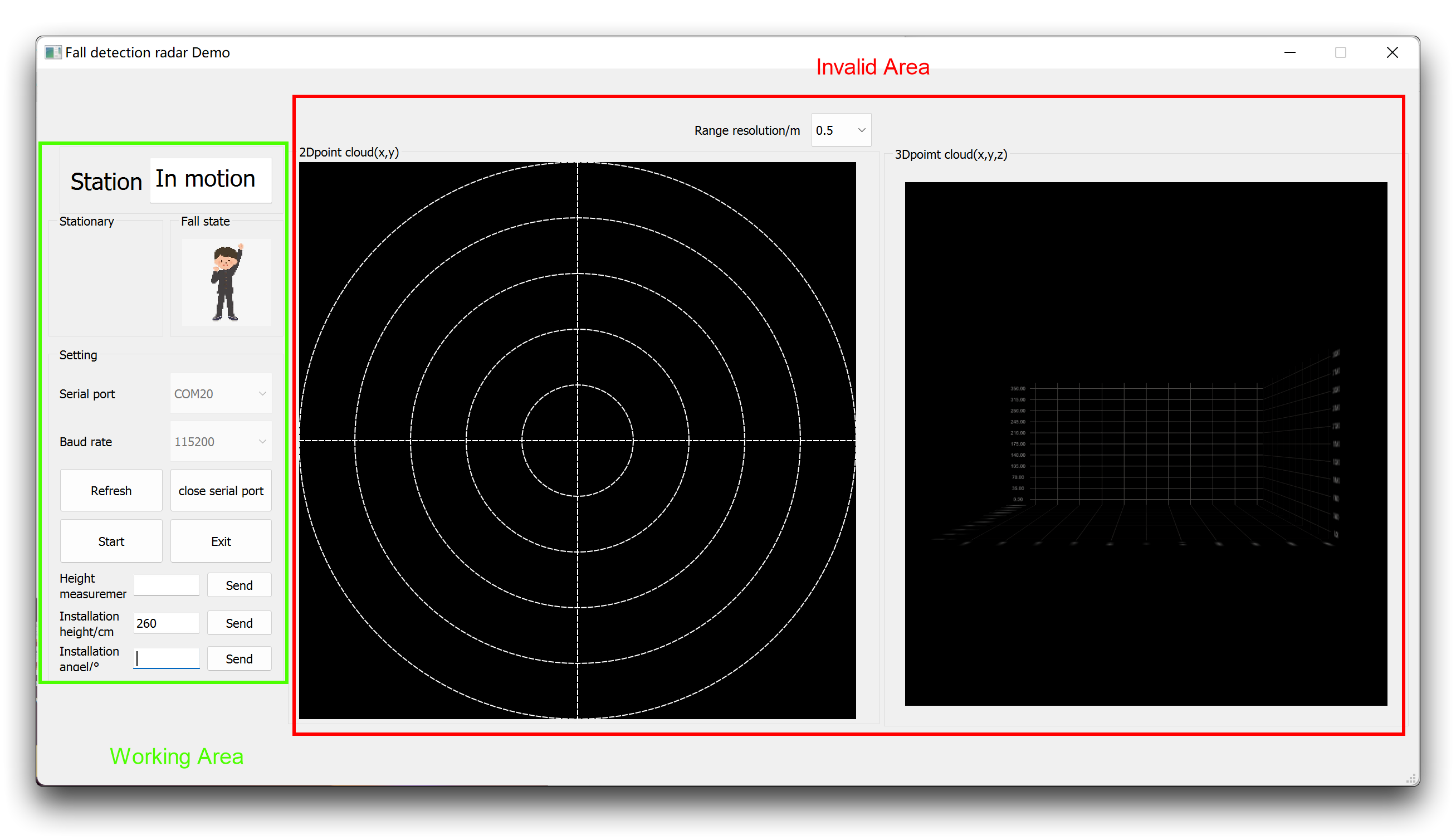
The following two sections explain the role of each part of the software.
-
Working Area
All functions of the upper computer are displayed in the work area only. The main content of the display is concentrated at the top of the workspace.
Station: Shows whether someone is present, moving or stationary.
Fall state: The state of the fall will be presented as an animation of the character. The state in the picture is no fall, and if someone falls, an animated picture of a person falling will be displayed.
Settings: Used to set the port number where the sensor is connected to the PC. Generally, when the sensor is connected to the computer via UART to USB, you need to click Refresh button to refresh the port, then select the newly appeared port number, then click Open button, and finally click Start button to enable the monitoring function.
Installing height/cm: Refers to the installation height. To ensure the accuracy of fall detection, please install the sensor accurately as follows. Please install it on top! The radar should be installed vertically with a horizontal deviation angle of ≤5° to ensure that the radar main beam covers the detection area; the radar installation height is recommended to be 2m≤H≤3m. No obvious obstructions and coverings in front of the radar. Affected by the radar installation height and radar beam range, the maximum radius of moving human detection in this installation mode is R3 ≈ 3 meters; the maximum radius of stationary human detection is R2 ≈ 2.25 meters; the radius of fall detection is R1 ≤ 2 meters.
For example, if my installation height is 2.6 meters, then I should fill in 260 and click the Send button.
-
Invalid Area
This area will not work at the moment, but only as a reserved interface.
This radar does not currently support range, speed, or point clouds!
Sensor development with Arduino
Arduino Library Overview
If this is your first time using Arduino, we highly recommend you to refer to Getting Started with Arduino.
The library code used in this example can be downloaded by clicking the icon below.
Function
Before we get started developing a sketch, let's look at the available functions of the library.
-
void recvRadarBytes()—— This function collects the data frames reported by the Sensor via the UART according to the frame headers and frame tails in the Sensor data protocol. Used in conjunction with theshowData()function, the collected data information can be printed out via the serial port.-
Input parameters: None
-
Return value: None
-
-
void showData()—— This function serves to print out the complete data frame reported by the Sensor at once via the serial port and needs to be used in conjunction with therecvRadarBytes()function.-
Input parameters: None
-
Return value: None
-
-
void HumanExis_Func()—— This function is responsible for parsing the data frames of the Sensor and outputting the relevant data on the state of the human presence.-
Input parameters: None
-
Return value:
-
unsigned int sensor_report—— The value returned indicates which status class the parsed data frame belongs to. The specific categories can be found in the Default Variables section. Human movement information is reported only when changes occur. -
int bodysign_val—— The value returned represents the value of the Human Movement Parameter. This value is reported once per second.
-
-
-
void Fall_Detection()—— This function is used to parse and return the detection of a fall. The detection is stored in the variable sensor_report.-
Input parameters: None
-
Return value: -
unsigned int sensor_report—— The value returned indicates which status class the parsed data frame belongs to. The specific categories can be found in the Default Variables section. Fall information is reported only when changes occur.
-
-
void send_func(const unsigned char* buff, int len, bool cyclic /*=false*/)—— The function is used for sending query frames and command frames.-
Input parameters:
-
buff—— The data frame you want to send to the Sensor. -
len—— The length of the data frame you want to send to the Sensor. -
cyclic—— Cyclic send switch. The default is false, which can be set to true if you wish to send this data frame cyclically.
-
-
Return value: None
-
-
void reset_func()—— The function serves to reset the Sensor.-
Input parameters: None
-
Return value: None
-
Default Variables
#define MESSAGE_HEAD1 0x53      //Data frame header1
#define MESSAGE_HEAD2 0x59      //Data frame header2

#define MESSAGE_END1  0x54      //End1 of data frame
#define MESSAGE_END2  0x43      //End2 of data frame

#define HUMAN_PSE_RADAR 0x80    //Human presence data

#define PRESENCE_INF 0x01       //Presence Information
#define SOMEONE_HERE 0x01       //Someone here
#define NOONE_HERE 0x00         //Noone here

#define MOVE_INF 0x02           //Campaign Information
#define PSE_NONE 0x00           //None
#define STATIONARY 0x01         //A person is stationary
#define MOVEMENT 0x02           //A person in motion

#define BODY_SIG 0x03           //Body movement information

#define MOVE_DIS 0x0E           //Determine the distance at which the movement occurs

#define FALL_DETECTION 0x83     //Fall data markers

#define FALL_STATE 0x01         //Fall status marker
#define NO_FALL 0x00            //No falls detected
#define FALLING 0x01            //Fall detected

#define RESIDENT_STATE 0x05     //Resident status
#define NO_RESIDENT 0x00        //No stationary residency
#define RESIDENT 0x01           //There is a stationary residency

#define reset_frame_len 10      //Reset data frame length
//Reset data frame
const unsigned char fall_reset_frame[10] = {0x53, 0x59, 0x01, 0x02, 0x00, 0x01, 0x0F, 0xBF, 0x54, 0x43};

//Return status, Use in arduino
#define NOONE 0x01
#define SOMEONE 0x02
#define NONEPSE 0x03
#define STATION 0x04
#define MOVE 0x05
#define BODYVAL 0x06
#define MOVEDIS 0x07

#define NOFALL 0x08
#define FALL 0x09
#define NORESIDENT 0x10
#define RESIDENCY 0x11

unsigned int sensor_report = 0, bodysign_val = 0, total_detect = 0, height_0005 = 0, height_0510 = 0, height_1015 = 0, height_1520 = 0;
Installation
Step 1. You need to Install an Arduino Software.

Step 2. Launch the Arduino application.
Step 3. Select your development board model and add it to the Arduino IDE.
-
If you want to use Seeeduino V4.2 for the later routines, please refer to this tutorial to finish adding.
-
If you want to use Seeeduino XIAO for the later routines, please refer to this tutorial to finish adding.
-
If you want to use XIAO RP2040 for the later routines, please refer to this tutorial to finish adding.
-
If you want to use XIAO BLE for the later routines, please refer to this tutorial to finish adding.
-
If you want to use XIAO ESP32C3 for the later routines, please refer to this tutorial to finish adding.
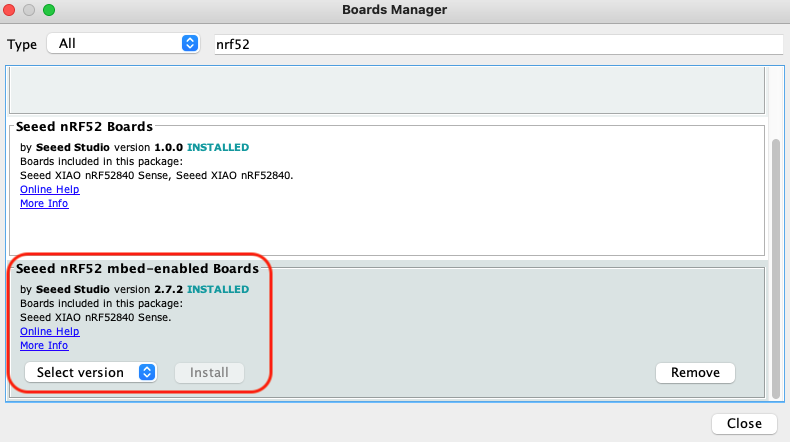
For XIAO nRF52840, please select Seeed nRF52 mbed-enabled Boards, otherwise an error may be reported when running programs.
Step 4. Install the Arduino code library.
Start by getting the code base from GitHub and downloading it to your local computer.
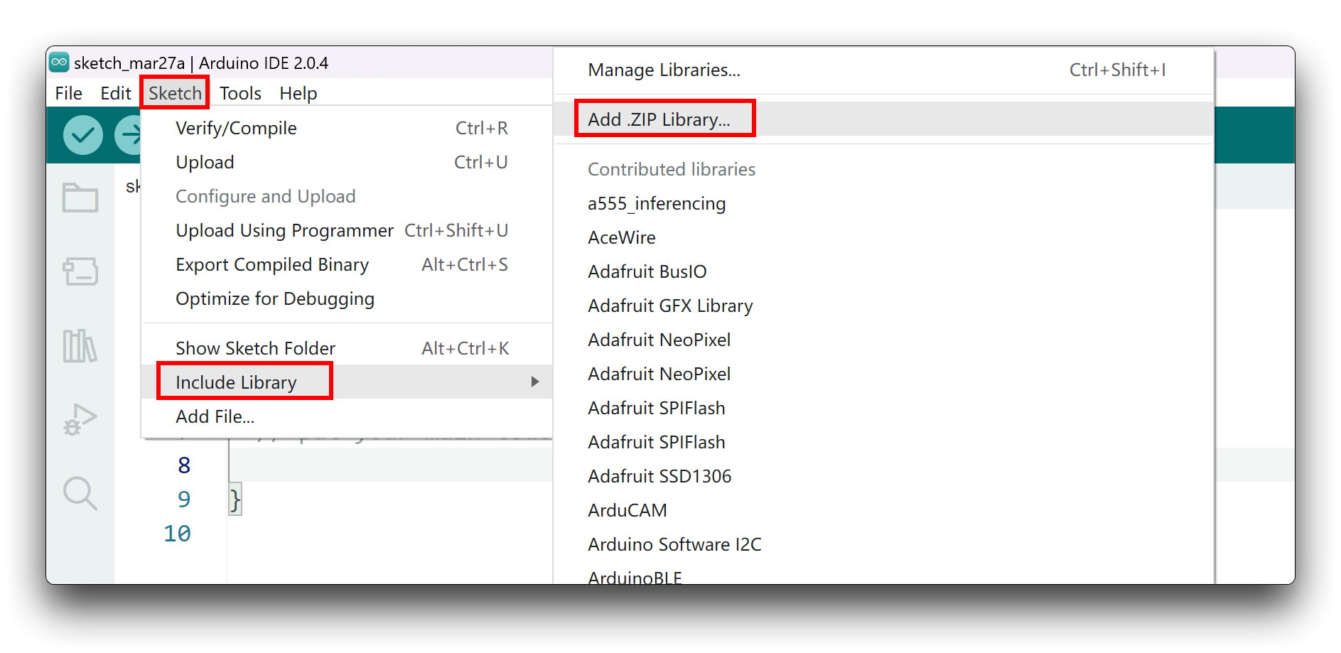
Since you have downloaded the zip Library, open your Arduino IDE, click on Sketch > Include Library > Add .ZIP Library. Choose the zip file you just downloaded,and if the library install correct, you will see Library added to your libraries in the notice window. Which means the library is installed successfully.
Arduino Example
Now that we have our library installed and we understand the basic functions, let's run some examples for our XIAO BLE to see how it behaves.
Materials Required
Before completing the following examples, you will need to prepare the following materials.
|  |  |
| 60GHz mmWave Radar Sensor | Seeed XIAO BLE nRF52840 Sense | 2mm to 2.54mm Pitch Ribbon Cable |
Step 1. Connect the device to the computer through the main board. The wiring diagram is shown in the table below.
 | |||
| Seeed Studio XIAO nRF52840 | MR60FDA1 Sensor | ||
| 5V | --> | 5V | |
| GND | --> | GND | |
| RX | --> | D6 | |
| TX | --> | D7 | |
Step 2. In the menu bar in the upper left corner of the Arduino IDE, select tool, choose the type of development board you are using, and select the corresponding serial port.
If you are using MacOS, the serial port name of the device will often start with /dev/cu.usbmodem xxx, ending with the name of the device. If you are using Windows, the device's serial port name will often begin with COM, again ending with the device's name.

In this example, we will demonstrate how the radar works with our popular product XIAO BLE.
Demo1 Raw data export
This example will guide you through the process of printing out the raw data reported by the Sensor via the serial port.
The following example program is in the examples folder of the library called MR60FDA1_print_rawdata.
#include "Arduino.h"
#include <60ghzfalldetection.h>

//#include <SoftwareSerial.h>
// Choose any two pins that can be used with SoftwareSerial to RX & TX
//#define RX_Pin A2
//#define TX_Pin A3

//SoftwareSerial mySerial = SoftwareSerial(RX_Pin, TX_Pin);

// we'll be using software serial
//FallDetection_60GHz radar = FallDetection_60GHz(&mySerial);

// can also try hardware serial with
FallDetection_60GHz radar = FallDetection_60GHz(&Serial1);

void setup() {
  // put your setup code here, to run once:
  Serial.begin(115200);
  Serial1.begin(115200);

  //  mySerial.begin(115200);

  while(!Serial);   //When the serial port is opened, the program starts to execute.

  Serial.println("Readly");
}

void loop()
{
  // put your main code here, to run repeatedly:
  radar.recvRadarBytes();           //Receive radar data and start processing
  radar.showData();                 //Serial port prints a set of received data frames
  delay(200);                       //Add time delay to avoid program jam
}
If you are using XIAO ESP32 series and there is no data feedback from mmwave radar. You can try to change the code above from Serial1.begin(115200); to Serial1.begin(115200, SERIAL_8N1, D7, D6);.
In this program, we are using the XIAO nRF52840's hardware Serial1 port to connect to the Sensor and use the hardware Serial port Serial to output data, so we need to initialise this serial port separately in the initialisation function Setup().
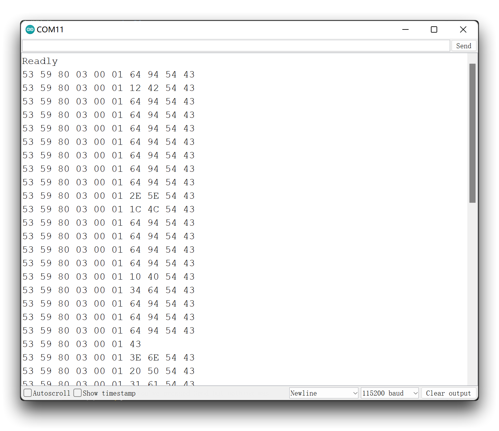
In the main loop() function we use the function recvRadarBytes() to receive data frames from the Sensor and then use the showData() function to print out the received data frames via the serial port.
In this program, it is important to note that there is an interval between the reception and output of every two data frames to avoid a jam on the main board. This time should be no less than 150ms.
This means that there is no way for the main board to receive all the data frames reported by the Sensor, but as the number of frames reported by the Sensor is very large and frequent, this does not affect the accuracy of using the Sensor to determine the environment.
Upload program. Opening your serial monitor to a baud rate of 115200 should show the result. The output should look something like the below image.
Demo2: Use of human presence detection function
In this example, we will explain how to use the function of human presence detection and print out all the values of this function in the function through the serial monitor.
The following example program is in the examples folder of the library called MR60FDA1_human_existence_inf_output.
#include "Arduino.h"
#include <60ghzfalldetection.h>
//#include <SoftwareSerial.h>
// Choose any two pins that can be used with SoftwareSerial to RX & TX
//#define RX_Pin A2
//#define TX_Pin A3
//SoftwareSerial mySerial = SoftwareSerial(RX_Pin, TX_Pin);
// we'll be using software serial
//FallDetection_60GHz radar = FallDetection_60GHz(&mySerial);
// can also try hardware serial with
FallDetection_60GHz radar = FallDetection_60GHz(&Serial1);
void setup() {
// put your setup code here, to run once:
Serial.begin(115200);
Serial1.begin(115200);
// mySerial.begin(115200);
while(!Serial); //When the serial port is opened, the program starts to execute.
Serial.println("Readly");
}
void loop()
{
// put your main code here, to run repeatedly:
radar.HumanExis_Func(); //Human existence information output
if(radar.sensor_report != 0x00){
switch(radar.sensor_report){
case NOONE:
Serial.println("Nobody here.");
Serial.println("----------------------------");
break;
case SOMEONE:
Serial.println("Someone is here.");
Serial.println("----------------------------");
break;
case NONEPSE:
Serial.println("No human activity messages.");
Serial.println("----------------------------");
break;
case STATION:
Serial.println("Someone stop");
Serial.println("----------------------------");
break;
case MOVE:
Serial.println("Someone moving");
Serial.println("----------------------------");
break;
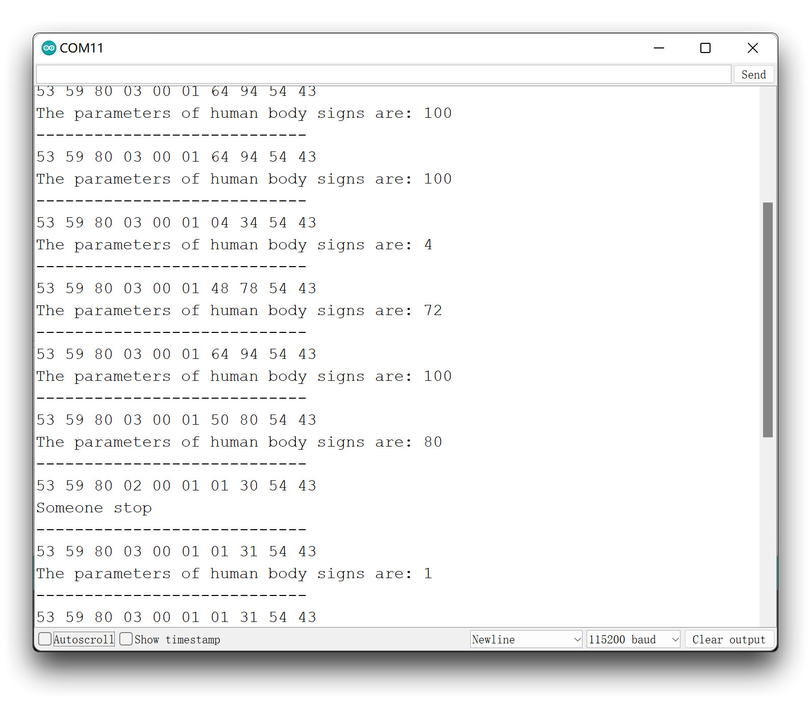
case BODYVAL:
Serial.print("The parameters of human body signs are: ");
Serial.println(radar.bodysign_val, DEC);
Serial.println("----------------------------");
break;
}
}
delay(200); //Add time delay to avoid program jam
}
If you are using XIAO ESP32 series and there is no data feedback from mmwave radar. You can try to change the code above from Serial1.begin(115200); to Serial1.begin(115200, SERIAL_8N1, D7, D6);.
In this example, the function to detect the presence of a human body is implemented by the HumanExis_Func() function. The basic logic of the program implementation is that the HumanExis_Func() function assigns the status information reported by the sensor to the sensor_report variable. Based on the value of sensor_report, we then print out all the values in that state through the serial port.
Note that the sensor_report corresponds to the data output from the serial port under indentation. For example, the bodysign_val variable representing the sign parameter is only valid when sensor_report is BODYVAL, and is not present in other sensor_reports reported by the sensor.
Upload program. Opening your serial monitor to a baud rate of 115200 should show the result. The output should look something like the below image.
Demo3: Detection of human falls
In this example, we will use the Fall_Detection() function to detect the human falls.
The principle of state output for falls is that there is content output only when the sensor detects a change in the state of the fall.
The following example program is in the examples folder of the library called MR60FDA1_Fall_detection.
#include "Arduino.h"
#include <60ghzfalldetection.h>

//#include <SoftwareSerial.h>
// Choose any two pins that can be used with SoftwareSerial to RX & TX
//#define RX_Pin A2
//#define TX_Pin A3

//SoftwareSerial mySerial = SoftwareSerial(RX_Pin, TX_Pin);

// we'll be using software serial
//FallDetection_60GHz radar = FallDetection_60GHz(&mySerial);

// can also try hardware serial with
FallDetection_60GHz radar = FallDetection_60GHz(&Serial1);

void setup() {
  // put your setup code here, to run once:
  Serial.begin(115200);
  Serial1.begin(115200);

  //  mySerial.begin(115200);

  while(!Serial);   //When the serial port is opened, the program starts to execute.

  Serial.println("Readly");
}

void loop()
{
  // put your main code here, to run repeatedly:
  radar.Fall_Detection();           //Receive radar data and start processing
  if(radar.sensor_report != 0x00){
    switch(radar.sensor_report){
        case NOFALL:
            Serial.println("The sensor detects this movement is not a fall.");
            Serial.println("----------------------------");
            break;
        case FALL:
            Serial.println("The sensor detects a fall.");
            Serial.println("----------------------------");
            break;
        case NORESIDENT:
            Serial.println("The sensors did not detect anyone staying in place.");
            Serial.println("----------------------------");
            break;
        case RESIDENCY:
            Serial.println("The sensor detects someone staying in place.");
            Serial.println("----------------------------");
            break;
    }
  }
  delay(200); //Add time delay to avoid program jam
}
If you are using XIAO ESP32 series and there is no data feedback from mmwave radar. You can try to change the code above from Serial1.begin(115200); to Serial1.begin(115200, SERIAL_8N1, D7, D6);.
Among the fall detection functions, there is also a function for dwell detection. The main function of this function is to assist the user or the sensor to determine whether the human body has fallen or not. When there is no human activity for a period of time after a dramatic change in acceleration in the vertical direction (i.e., staying in place), there is a high probability that the sensor will determine that someone has fallen and is unconscious.
Demo4: Send data to Sensor
Based on the details provided in the user manual, the user can send command frames to the sensor to query or set certain states or modes of the sensor according to the actual needs.
The .ino file named MR60FDA1_Send_frame in the examples folder of the sensor library shows us how to send a program that queries the device ID to the sensor.
#include "Arduino.h"
#include <60ghzfalldetection.h>

//#include <SoftwareSerial.h>
// Choose any two pins that can be used with SoftwareSerial to RX & TX
//#define RX_Pin A2
//#define TX_Pin A3

//SoftwareSerial mySerial = SoftwareSerial(RX_Pin, TX_Pin);

// we'll be using software serial
//FallDetection_60GHz radar = FallDetection_60GHz(&mySerial);

// can also try hardware serial with
FallDetection_60GHz radar = FallDetection_60GHz(&Serial1);

const unsigned char DevID_buff[10] = {0x53, 0x59, 0x02, 0xA1, 0x00, 0x01, 0x0F, 0x5F, 0x54, 0x43};

void setup() {
  // put your setup code here, to run once:
  Serial.begin(115200);
  Serial1.begin(115200);

  //  mySerial.begin(115200);

  while(!Serial);   //When the serial port is opened, the program starts to execute.

  Serial.println("Readly");
}

void loop()
{
  // put your main code here, to run repeatedly:
  radar.send_func(DevID_buff, 10, false);
  delay(50);                       //Do not set the delay time too long, as this may affect the reception of the data frames returned by the radar.
}
If you are using XIAO ESP32 series and there is no data feedback from mmwave radar. You can try to change the code above from Serial1.begin(115200); to Serial1.begin(115200, SERIAL_8N1, D7, D6);.
In the program of this example, you can see that an array DevID_buff[10] is defined, which stores the hexadecimal number of your query device ID, one location per byte.
And the sending is done by send_func(). The parameters passed in are the array of frames to be sent, the length of the array, and whether to send in a loop.
If you need to send your own command frames, then you need to define the correct array according to the frame format provided in the user manual.
Regarding the calculation of the check digit "sum".
All data frames have a checksum bit to ensure that the data is sent or received accurately. The checksum bit is usually in the penultimate bit of the data frame. It is calculated by adding up all the bits preceding the check bit and taking the lower two bits in hexadecimal. Let's take the example of a data frame that queries the device ID.

It can be seen that the checksum bit is in the penultimate bit of the entire data frame. Then we start by adding all the previous hexadecimal numbers.
0x53 + 0x59 + 0x02 + 0xA2 + 0x00 + 0x01 + 0x0F = 0x0160
Then we need to take the lower two digits of it, which would be 60, so the checksum of this data frame is 60. If we want to look up the ID of the Sensor, then you can define the following array.
const unsigned char DevID_buff[10] = {0x53, 0x59, 0x02, 0xA1, 0x00, 0x01, 0x0F, 0x60, 0x54, 0x43};
Upload program. Opening your serial monitor to a baud rate of 115200 should show the result. The output should look something like the below image.
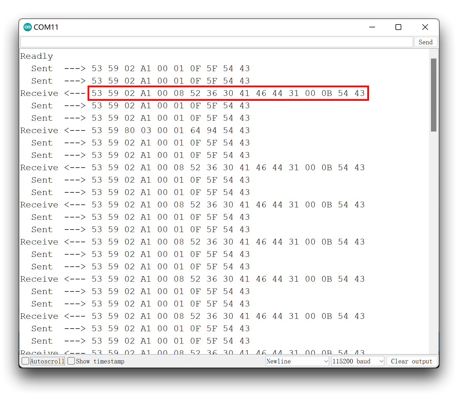
At this point please check the data frames returned and if they match the data frames returned as described in the user manual.
Normally, our commands do not need to be repeated to the Sensor, but as the Sensor replies with messages so fast that we cannot be sure that we will receive the exact data message returned by the Sensor. There are two solutions to this problem.
- Re-upload the above procedure several times.
- Set the third parameter of the
send_func()function (cyclic sending) totrue. Please note, however, that repeatedly sending data frames of the setting type may cause the Sensor to jam, so please use this function with caution. If the Sensor is stuck, disconnect the 5V supply pin from the Sensor and wait a few moments for the function to resume.
Demo5: Reset Sensor
There may be times when you have problems with your Sensor detecting anomalies or when you want to clear all settings on your Sensor, then you can reset your Sensor according to this example.
The following example program is in the examples folder of the library called MR60FDA1_Reset_sensor.
#include "Arduino.h"
#include <60ghzfalldetection.h>

//#include <SoftwareSerial.h>
// Choose any two pins that can be used with SoftwareSerial to RX & TX
//#define RX_Pin A2
//#define TX_Pin A3

//SoftwareSerial mySerial = SoftwareSerial(RX_Pin, TX_Pin);

// we'll be using software serial
//FallDetection_60GHz radar = FallDetection_60GHz(&mySerial);

// can also try hardware serial with
FallDetection_60GHz radar = FallDetection_60GHz(&Serial1);

void setup() {
  // put your setup code here, to run once:
  Serial.begin(115200);
  Serial1.begin(115200);

  //  mySerial.begin(115200);

  while(!Serial);   //When the serial port is opened, the program starts to execute.

  Serial.println("Readly");

  radar.reset_func();
}

void loop()
{
  // put your main code here, to run repeatedly:
}
If you are using XIAO ESP32 series and there is no data feedback from mmwave radar. You can try to change the code above from Serial1.begin(115200); to Serial1.begin(115200, SERIAL_8N1, D7, D6);.
Resetting the Sensor is very simple, you just need to call reset_func(). The reset only needs to be executed once, so we use it in the Setup() function.
Demo6: Using Arduino/Seeeduino
Our library is Arduino compatible and you can also choose the Arduino you have on hand to develop your Sensor project.
The MR60FDA1 Sensor communicates using the UART serial port, you just need to connect the Sensor to your Arduino as wired below.
| MR60FDA1 Sensor | MCU | |
| 5V | --> | 5V |
| GND | --> | GND |
| RX | --> | soft serial port TX |
| TX | --> | soft serial port RX |
All the functions are applied in the same way as in Demo1 to Demo5 above, so we will not repeat them in this example. In this example, we will give you an overview of how to use the Arduino's soft serial port to get data information from the Sensor.
For notes on the Arduino soft serial port, please refer to the official Arduino documentation.
To avoid data confusion caused by using Serial for both output and data transmission, on the Arduino side we usually use a soft serial port.
The import of the soft serial port library and the definition of the RX and TX pins need to be done earlier in the program. The following program defines the A2 and A3 pins as the RX and TX pins of the soft serial port.
#include <SoftwareSerial.h>
//Choose any two pins that can be used with SoftwareSerial to RX & TX
#define RX_Pin A2
#define TX_Pin A3

SoftwareSerial mySerial = SoftwareSerial(RX_Pin, TX_Pin);

//we'll be using software serial
FallDetection_60GHz radar = FallDetection_60GHz(&mySerial);
Also, don't forget to set the baud rate for the soft serial port in the Setup() function.
void setup() {
  // put your setup code here, to run once:
  Serial.begin(115200);

  mySerial.begin(115200);

  while(!Serial);   //When the serial port is opened, the program starts to execute.

  Serial.println("Readly");
}
Using Demo1 as an example, if you want to use the Arduino to print the reported data frames from the Sensor, then the complete program is as follows.
#include "Arduino.h"
#include <60ghzfalldetection.h>

#include <SoftwareSerial.h>
// Choose any two pins that can be used with SoftwareSerial to RX & TX
#define RX_Pin A2
#define TX_Pin A3

SoftwareSerial mySerial = SoftwareSerial(RX_Pin, TX_Pin);

// we'll be using software serial
FallDetection_60GHz radar = FallDetection_60GHz(&mySerial);

void setup() {
  // put your setup code here, to run once:
  Serial.begin(115200);

  mySerial.begin(115200);

  while(!Serial);   //When the serial port is opened, the program starts to execute.

  Serial.println("Readly");
}

void loop()
{
  // put your main code here, to run repeatedly:
  radar.recvRadarBytes();           //Receive radar data and start processing
  radar.showData();                 //Serial port prints a set of received data frames
  delay(200);                       //Add time delay to avoid program jam
}
Demo7: Direct connection to PC for data
You can refer to this routine if you want to use an upper computer designed for Sensor, or if you want to use the serial software to get a complete data frame.
Connect the Sensor directly to the computer's usb port via a UART to USB device. The wiring is shown in the table below.
| |||
| UART to USB | MR60FDA1 Sensor | ||
| 5V | --> | 5V | |
| GND | --> | GND | |
| RX | --> | TX | |
| TX | --> | RX | |
Use a software like serial debugging assistant to select the serial port where the Sensor is located.
MR60FDA1 Sensor needs 5V power supply, otherwise the Sensor may not work properly.
After a successful connection, you will see the Sensor sending a steady stream of messages.
At the same time, you can also send data frames to the Sensor via the software's send function.
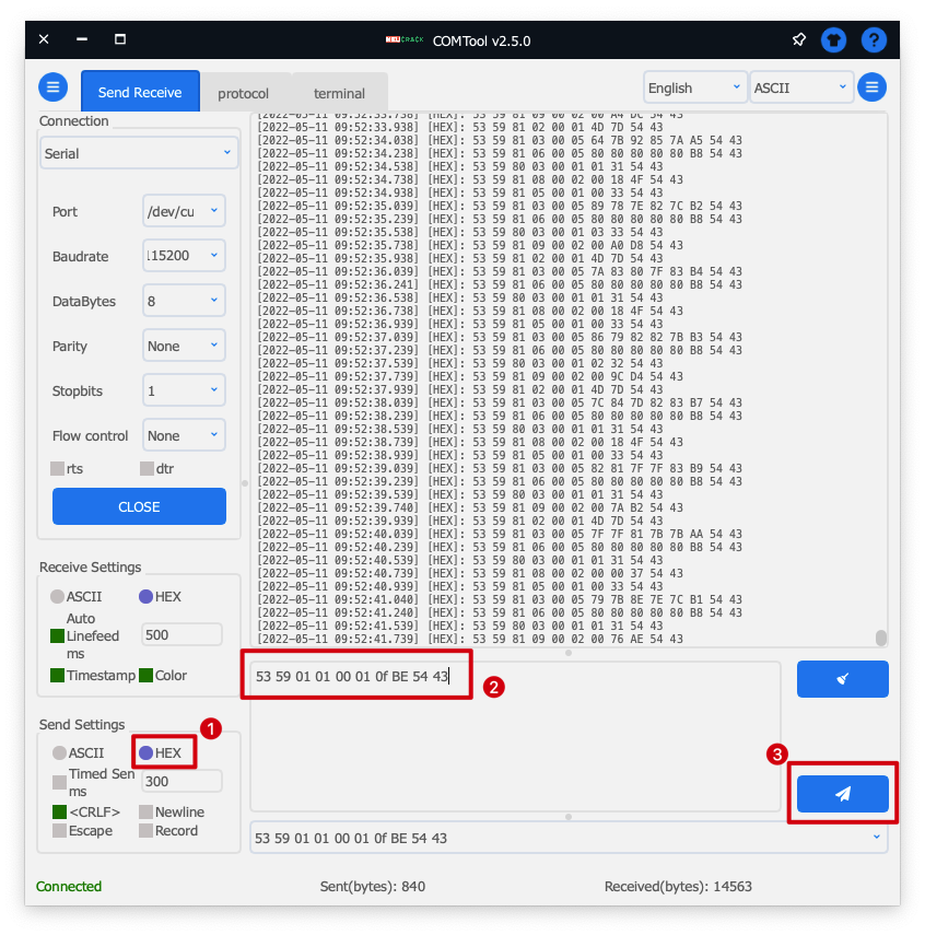
If you choose ASCII as the format for sending data, each data set needs to be prefixed with 0x. If you choose HEX, then each set of data does not need to be prefixed with 0x.
Troubleshooting
FAQ1: Can this Sensor detect more than one person at a time in the same environment?
A: Not available. This Sensor can only be used on a single living object. If more than one person or animal is in the monitoring range, this will have an effect on the results of the monitoring.
FAQ2: Why can't I see anything in the serial monitor with the XIAO ESP32C3?
XIAO ESP32C3 serial port function is not quite consistent with the general Arduino hardware, and using Serial1 directly may cause the USB serial port not to work. For related application cases, please go to the Serial chapter of XIAO ESP32C3 for details.
Resources
- [PDF] Universal Protocol
- [PDF] User manual V1.3
- [PDF] Seeed Studio MMWave Sensor Case Design
- [EXE] Upper Computer Software
Tech Support & Product Discussion
Thank you for choosing our products! We are here to provide you with different support to ensure that your experience with our products is as smooth as possible. We offer several communication channels to cater to different preferences and needs.