Seeeduino Cortex M0
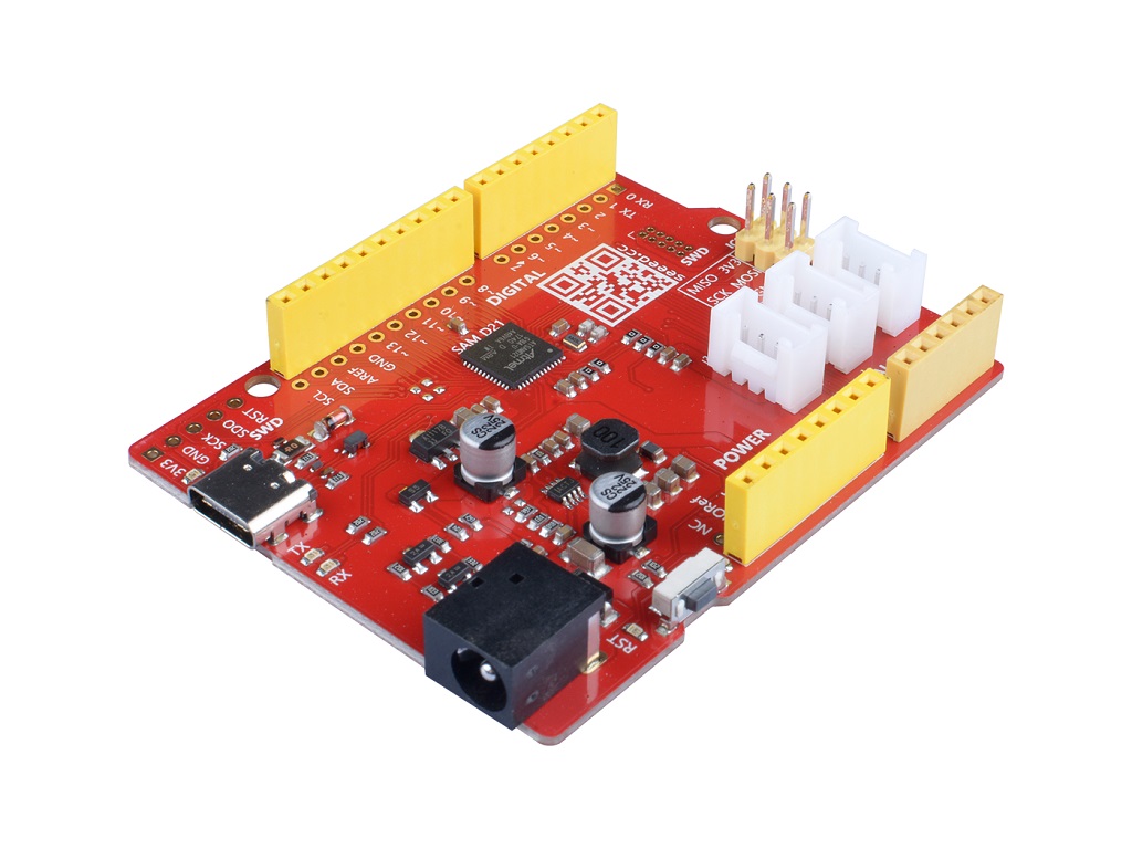
The Seeeduino Cortex-M0+ features an Atmel SAMD21 MCU which is based on a 32-bit ARM® Cortex®-M0+ processor. With the help of this powerful core, SAMD21 is much more powerful than AVR and can achieve many functions and more complex calculations that cannot be implemented on AVR chips.
The Seeeduino M0+ is a brand new product line that is fully compatible with Arduino Zero and we currently have Seeeduino Cortex-M0+ and Seeeduino Lotus Cortex-M0+ in this serial.
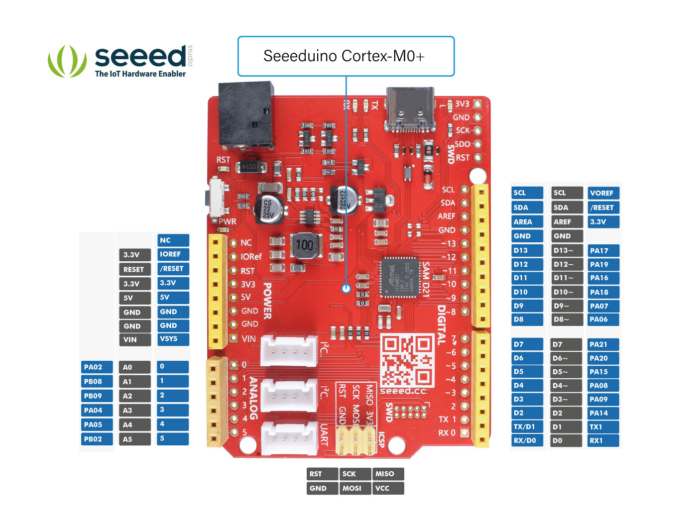
The Seeeduino Cortex-M0+ has the same header pinout as the Seeeduino Lotus Cortex-M0+, including 14 digital I/O (10 PWM output) and 6 analog I/O. On the meantime, it provides 3 on-board Grove connector: two I2C and 1 UART. If you want to use more grove port, you can use a Base Shield V2 to work with this board.
On top of that, Seeeduino Cortex-M0+ is the first Seeeduino development board with a USB type C interface. USB Type C is the future trend: the plugs are reversible, higher data transfer rate, and more scalable functions. We will introduce more development boards with Type C. You can use type C to supply power and transmit data or use the 7~15V DC jack to supply power for this board.

Feature
- ARM Cortex-M0+ CPU running at up to 48MHz
- 256KB in-system self-programmable Flash
- 32KB SRAM Memory
- Compatible with Arduino Zero
- 10-bit, 350ksps Digital-to-Analog Converter (DAC)
- One 12-bit, 350ksps Analog-to-Digital Converter (ADC) with up to 20 channels
- USB type C for power and data
Specification
| Item | Value |
|---|---|
| Microcontroller | SAM D21 |
| Power Input | USB Type C |
| Operating Voltage | USB:5V |
| Digital I/O Pins | 14 |
| PWM Channels | 10 |
| Analog Input Channels | 6 |
| DC Current per I/O Pin | 40 mA |
| IO Input Voltage | 3.3V |
| SRAM | 32 KB |
| Flash Memory | 256KB |
| Maximum CPU frequency | 48 MHz |
Hardware Overview

UART
For the Seeed M0 serial board, there are 3 UART port as the following picture shown. When you code with Arduino IDE, you should use the corresponding port name, which is:
SerialUSB or Serial
for type C port;
Serial1
for Grove UART port;
and
Serial2
for UART pins in the header
.jpg)
Pinout
Getting Started
Hardware
Materials required
- Seeeduino Cortex-M0+ x1
- Computer x1
- USB typc cable x1
Some USB cables can only supply power and cannot transfer data. If you don't have a usb cable or don't know if your usb cable can transmit data, you can check seeed USB type C support USB 3.1 .
Connect the Seeeduino Cortex-M0+ to your computer using the USB cable. The blue power LED (labelled PWR) should light on.
Software
- Step 1. You need to Install an Arduino Software.

Launch the Arduino application
Double-click the Arduino application (arduino.exe) you have previously downloaded.
If the Arduino Software loads in a different language, you can change it in the preferences dialog. See the Arduino Software (IDE) page for details.
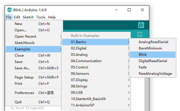
- Step 2. Open the Blink example
Open the LED blink example sketch: File > Examples >01.Basics > Blink.
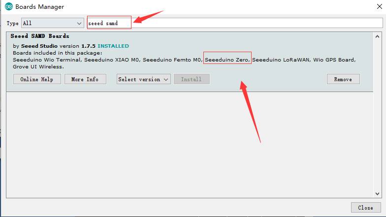
- Step 3. Add the Seeed Board
Please follow the Seeed Board Intallation Guide and serch the key word Seeeduino samd to add the Seeeduino Zero into your Arduino IDE.
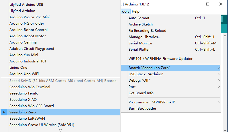
- Step 4. Select your board and port
You'll need to select the entry in the Tools > Board menu that corresponds to your Arduino. Selecting the Seeeduino zero.
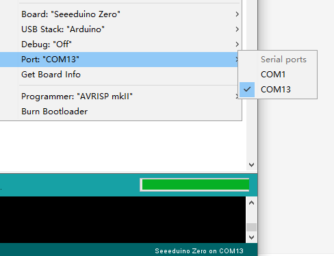
Select the serial device of the Arduino board from the Tools | Serial Port menu. This is likely to be COM3 or higher (COM1 and COM2 are usually reserved for hardware serial ports). To find out, you can disconnect your Arduino board and re-open the menu; the entry that disappears should be the Arduino board. Reconnect the board and select that serial port.
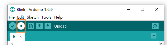
- Step 5.Upload the program
Now, simply click the "Upload" button in the environment. Wait a few seconds and if the upload is successful, the message "Done uploading." will appear in the status bar.
A few seconds after the upload finishes, you should see the pin 13 (L) LED on the board start to blink. If it does, congratulations! You've gotten Arduino up-and-running. If you have problems, please see the troubleshooting suggestions.
Schematic Online Viewer
Resources
- [ZIP] Seeeduino Cortex-M0+ v1.0 Eagle file
- [PDF] SAMD21-Datasheet
To use the UART of Seeeduino Cortex-M0+, you need to use ``
Tech Support & Product Discussion
Thank you for choosing our products! We are here to provide you with different support to ensure that your experience with our products is as smooth as possible. We offer several communication channels to cater to different preferences and needs.