Seeed Studio XIAO SAMD21 Get Started By Nanase
This is a document written by @nanase_coder. (Translated by Seeed from the original Japanese document: コインサイズ Arduino互換機 Seeed Studio XIAO SAMD21 を使ってみた). Thank you Nanase for sharing this with us!
Documentations
There are two documentations on the usage of Seeeduino XIAO which focus on different areas, check the table below for reference:
| Documentation by Seeed | Documentation by Nanase |
|---|---|
| Pinout Digram | Interface |
| Seeed Studio XIAO SAMD21 Getting Started | Seeed Studio XIAO SAMD21 with MicroSD Card(SPI) |
| Seeed Studio XIAO SAMD21 GPIO Usage | Seeed Studio XIAO SAMD21 with GPS(UART) |
| Seeed Studio XIAO SAMD21 Resources | Single Cycle IOBUS |
Features
- ARM Cortex M0 + CPU (SAMD21G18) 48MHz
- 256 KB Flash, 32 KB SRAM
- USB Type-C
- SPI, I2C, UART, DMA available
- coin size(21mm x 17.8mm)
- Logic level:3.3V
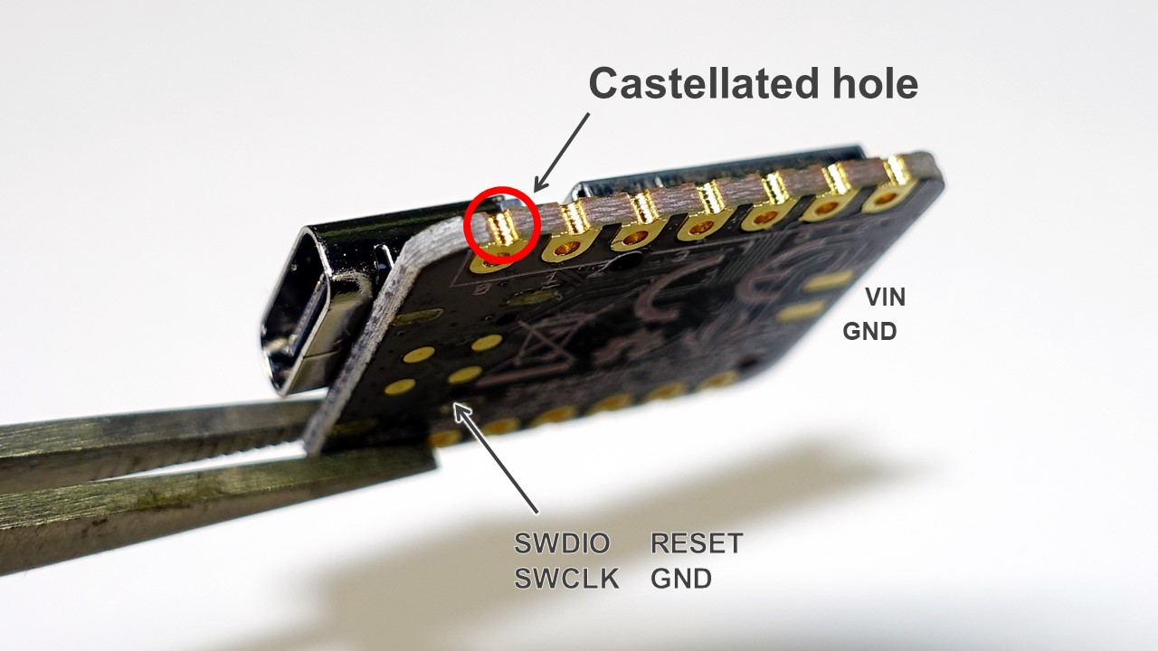
There are no components on the backside of the board, and all pins have castellated holes, making it easy to solder onto another board.
Part list
- 1 x Seeeduino XIAO
- 2 x 7pins header
- 4 x pasters

Castellated holes:
Specification
| Specification | |
|---|---|
| CPU | ARM Cortex-M0+ CPU(SAMD21G18) running at up to 48MHz(Multiply from 32.768 kHz) |
| Storage | 256KB Flash,32KB SRAM |
| I/O PINs | 14 GPIO PINs,11 analog PINs, 11 digital PINs, 1 DAC output Pin |
| Pin function | SPI, I2C, UART, PWM, external interrupt, SWD (Power Pad) |
| Logic level | 3.3V |
| LEDs: | 1 user LED, 1 power LED, two LEDs for serial port downloading |
| Power | USB Type-C interface, power pads at the back |
| Size | 21x17.8x3.5mm |
As you can see, it is a SAMD type Arduino and is similar to the Arduino MKR series, so technically, any library written for them can be used on Seeed Studio XIAO SAMD21. On the other hand, since it is different from the ATmega type Arduino like Arduino Uno, the library which depends on some specific register of ATmega cannot be used.
GPIO 14-pin refers to 11 pins on the side, reset pin, and SWD (SWDIO, SWCLK) on the back.
The UART in the pin function is different from the serial via USB and can be operated by Serial1.
Reset your Board
Check here and learn about how to add Seeed Studio XIAO SAMD21 to your Arduino IDE.
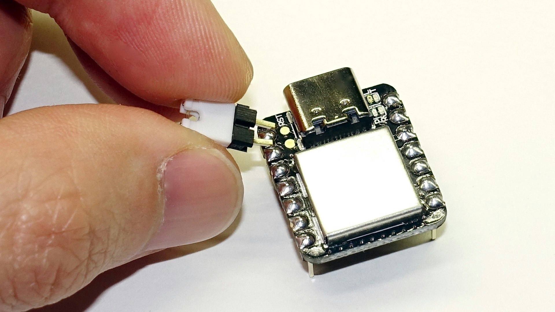
Seeed Studio XIAO SAMD21 does not have a reset button. Instead, there is a reset pad. Short connect this reset pad and apply GND to reset your board.
Bootloader Mode
Sometimes the program may crash or it is unable to upload the sketch. You can reset the board twice and enter Bootloader mode. In this mode, the LEDs flash slowly, and the Seeed Studio XIAO SAMD21 is recognized as a USB memory device. The serial port is separated from the normal mode, and it is always in sketch write mode without running the previous program on the board.
To return from bootloader mode to normal mode, upload a sketch or reset it twice quickly again.
If you enter bootloader mode when the Seeed Studio XIAO SAMD21 is not recognized as a USB device by the PC, the LED will blink rapidly.
LCD
Just like the original Arduino, select Basics> Blink from the sample sketch and upload.
void setup() {
  pinMode(LED_BUILTIN, OUTPUT);
}

void loop() {
  digitalWrite(LED_BUILTIN, HIGH);
  delay(1000);
  digitalWrite(LED_BUILTIN, LOW);
  delay(1000);
}
Contrary to the original Arduino, it is turned on at LOW and turned off at HIGH.
Two Blinkable Built-in LEDs
The official website describes two other built-in LEDs as two LEDs for serial port downloading. However, looking at the schematic, there is no physical pin connected to these RX and TX LEDs.
If you look at USBCore.cpp here, you can see that they are turned on by digitalWrite every time serial USB transmission / reception occurs, which means that the two LEDs are programmable.
uint32_t USBDeviceClass::recv(uint32_t ep, void *_data, uint32_t len)
{
    if (!_usbConfiguration)
        return -1;

#ifdef PIN_LED_RXL
    if (rxLEDPulse == 0)
        digitalWrite(PIN_LED_RXL, LOW);

    rxLEDPulse = TX_RX_LED_PULSE_MS;
#endif
The specific pin numbers are variant.h / variant.cpp like SAMD Arduino, and in case of Seeeduino XIAO, they are assigned to 11 and 12 as follows.
#define PIN_LED_13  (13u)
#define PIN_LED     PIN_LED_13
#define LED_BUILTIN PIN_LED

#define PIN_LED_RXL          (12u)
#define PIN_LED_TXL          (11u)
#define PIN_LED2             PIN_LED_RXL
#define PIN_LED3             PIN_LED_TXL
Below is a sketch of blinking three LEDs. The LEDs for RX and TX are blue.
void setup() {
  pinMode(LED_BUILTIN, OUTPUT);
  pinMode(PIN_LED2, OUTPUT);
  pinMode(PIN_LED3, OUTPUT);
}

void loop() {
  digitalWrite(LED_BUILTIN, HIGH);
  digitalWrite(PIN_LED2, HIGH);
  digitalWrite(PIN_LED3, HIGH);
  delay(1000);
  digitalWrite(LED_BUILTIN, LOW);
  digitalWrite(PIN_LED2, LOW);
  digitalWrite(PIN_LED3, LOW);
  delay(1000);
}
Interface
Serial over USB CDC
Unlike the ATmega type Arduino, the actual state of serial communication of Seeed Studio XIAO SAMD21 is USB CDC. In other words, it can perform faster than normal serial communication.
Therefore, specifying the baud rate by Serial.begin (speed) does not make sense, but except for that, it can be used as normal serial.
Measuring Speed
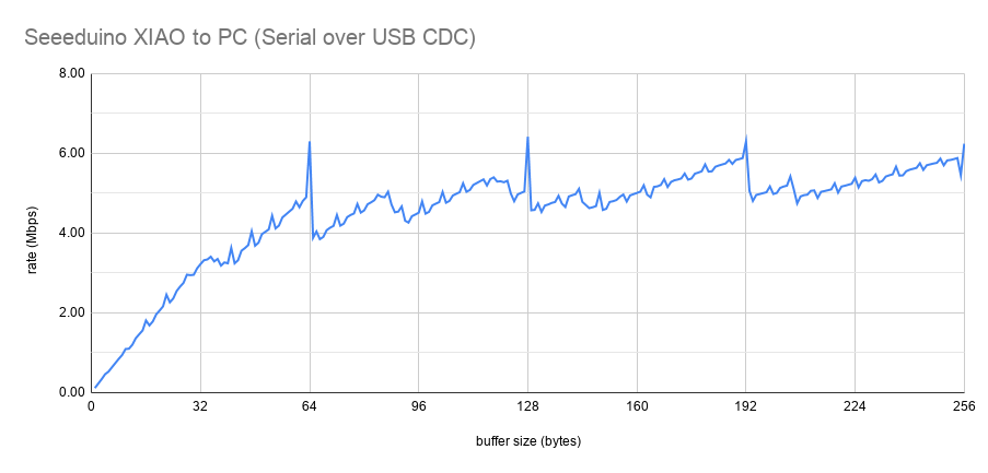
I used this sketch to measure the transfer speed from Seeed Studio XIAO SAMD21 to PC, and the transfer rate from the PC to Seeed Studio XIAO SAMD21 should be the same.
The horizontal axis is the buffer size(send at once using Serial.write (buf, len)).
If you send 1 byte at a time, you will only get 0.11 Mbps (14.53 KB / s), but if you send 64 bytes, it will be significantly faster at 6.30 Mbps (805.86 KB / s). You can infer that the size of the internal buffer is 64 bytes.
As mentioned above, the LED blinks in serial communication, but there was almost no decrease in speed due to this.
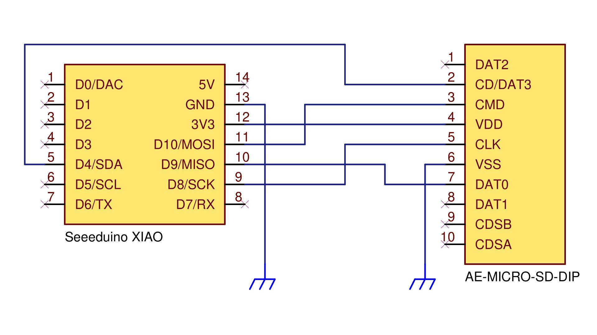
SPI (MicroSD Card)
Seeed Studio XIAO SAMD21 has a logic level of 3.3V. In other words, microSD card can be handled via SPI without a level shifter. Some function of SPI is different from that of ATmega type Arduino, please check here for more information.
Here we will read the microSD card using Akizuki Denshi's micro SD card slot DIP kit.
We use the Arduino sample code here, but the parameter of SD.begin (cs_pin) is specified as SS. According to variant.h, SS = 4, which is the same as D4 / A4 / SDA pins. Of course, you can specify other pins.

#include <SPI.h>
#include <SD.h>

File myFile;

void setup() {
  Serial.begin(9600);
  while (!Serial) ;

  Serial.print("Initializing SD card... ");

  if (!SD.begin(SS)) { // <-------------------------------- SS = D4/A4/SDA pin
    Serial.println("initialization failed!");
    while (1) ;
  }
  Serial.println("initialization done.");

  myFile = SD.open("test.txt", FILE_WRITE);

  if (myFile) {
    Serial.print("Writing to test.txt...");
    myFile.println("testing 1, 2, 3.");

    myFile.close();
    Serial.println("done.");
  }
  else
    Serial.println("error opening test.txt");

  myFile = SD.open("test.txt");
  if (myFile) {
    Serial.println("test.txt:");

    while (myFile.available())
      Serial.write(myFile.read());

    myFile.close();
  }
  else
    Serial.println("error opening test.txt");
}

void loop() { }
Result:
Initializing SD card...initialization done.
Writing to test.txt...done.
test.txt:
testing 1, 2, 3.
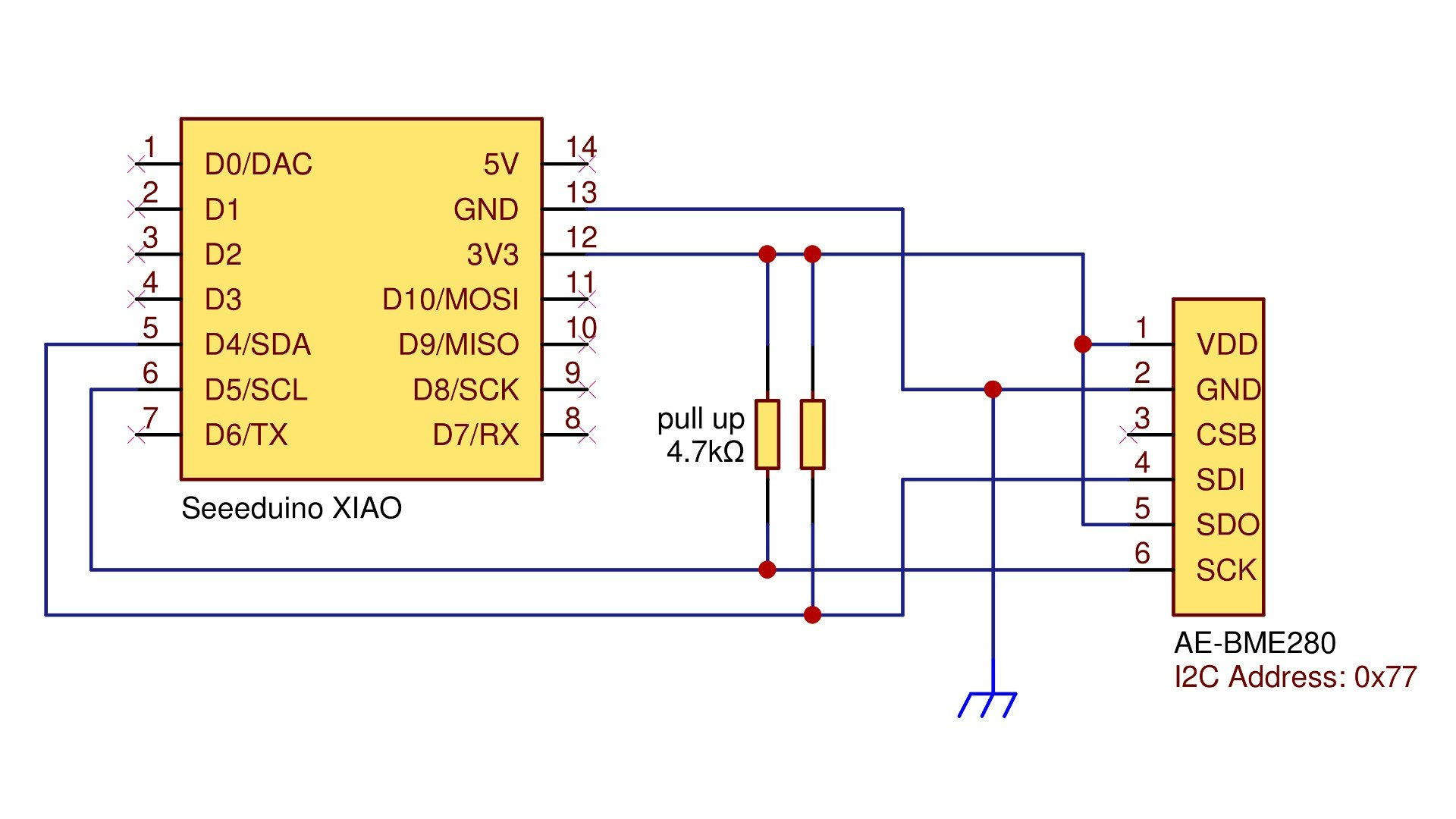
I2C
I2C is also available. 3.3V devices can be directly connected without a level shifter.
This time, we used BME280 to measure temperature and humidity and atmospheric pressure. The BME280 operates at 3.3V, so it can be connected without a level shifter. Check here for detailed instrcution of the connection between Arduino and BME280.

#include <Wire.h>
#include "SparkFunBME280.h"

BME280 sensor;

void setup() {
  Serial.begin(9600);
  Wire.begin();
  sensor.beginI2C(); // Wire を用いて I2C 接続開始
}

void loop() {
  Serial.print("Temp: ");
  Serial.print(sensor.readTempC(), 2);

  Serial.print(" °C, Humidity: ");
  Serial.print(sensor.readFloatHumidity(), 2);

  Serial.print(" %, Pressure: ");
  Serial.print(sensor.readFloatPressure() / 100.0, 1);
  Serial.println(" hPa");

  delay(5000);
}
Result:
Temp: 22.05 °C, Humidity: 44.99 %, Pressure: 1009.0 hPa
Temp: 22.05 °C, Humidity: 44.72 %, Pressure: 1008.9 hPa
Temp: 22.06 °C, Humidity: 44.81 %, Pressure: 1008.9 hPa
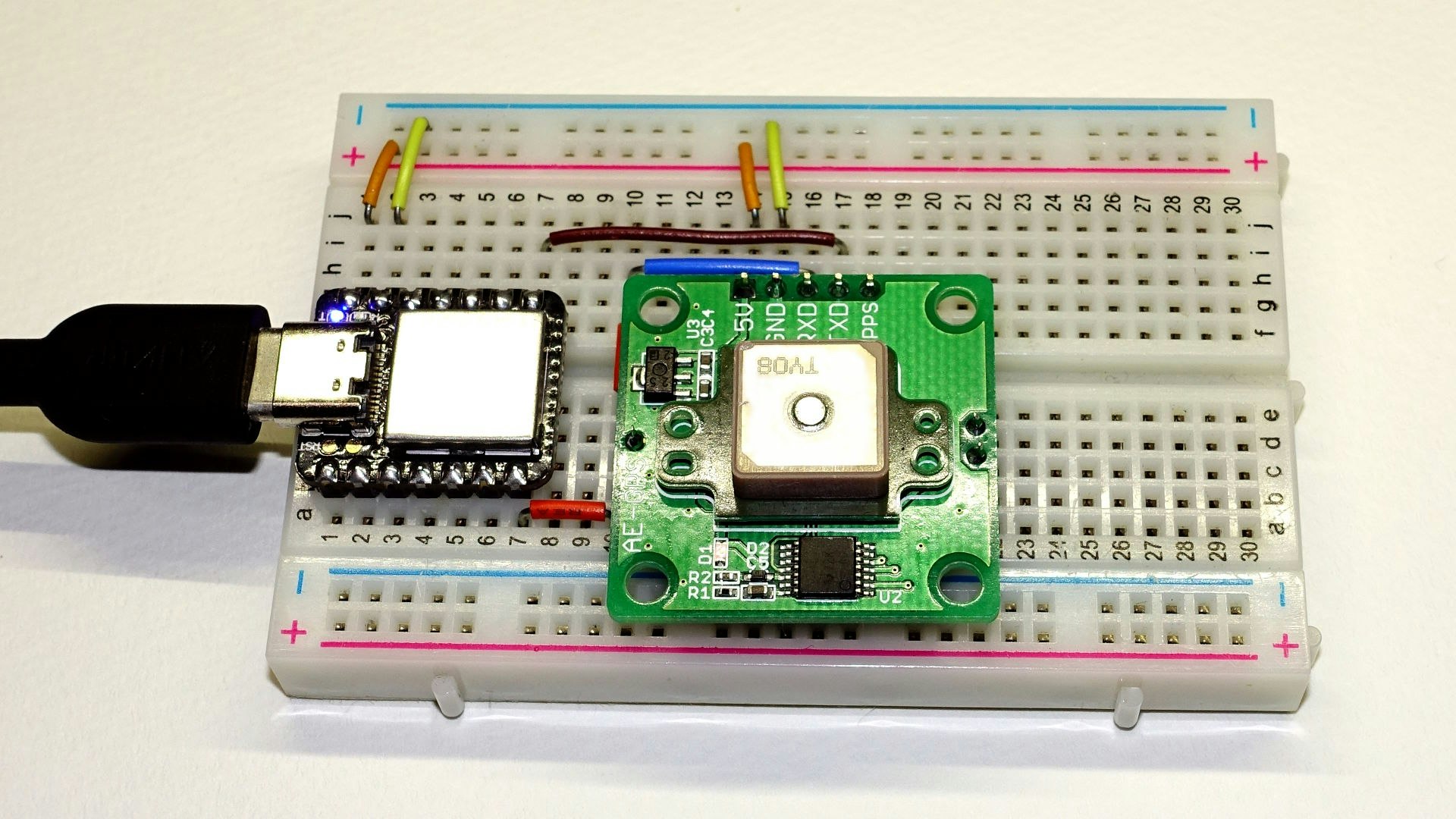
UART
As mentioned earlier, the physical UART pins are different from those on the USB CDC. Serial1 is used for serial communication using the TX and RX pins.
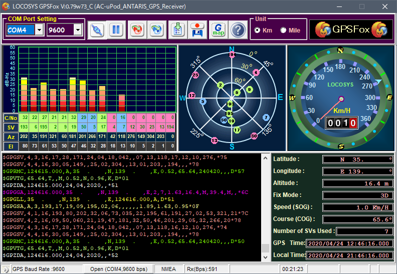
This time, we connect Seeed Studio XIAO SAMD21 to the GPS receiver kit and get NMEA information from the PC. It is a very simple job when using Xiao, which is just a bridge between gps kit and pc serial.

void setup() {
  Serial.begin(9600);
  Serial1.begin(9600);
}

void loop() {
  if (Serial.available()) {
    char c = (char)Serial.read();
    Serial1.write(c);
  }

  if (Serial1.available()) {
    char c = (char)Serial1.read();
    Serial.write(c);
  }
}
This time we use GPSFox to browse NMEA information. The coordinates can be measured easily.
Others
DMA
As one of the features of SAMD type Arduino, you can use DMA on Xiao. Check here for more information about DMA.
Single Cycle IOBUS
Cortex M0+ has a function called Single Cycle IOBUS that can operate GPIO output in one clock cycle. Writing to a specific register can invert the logic, disable the pin, or change the pin drive current.
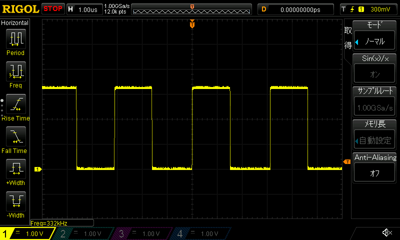
DigitalWrite
You can use digitalWrite to create a pulse, which is a method that works with any Arduino board - just repeating the overhead.
void setup() {
  pinMode(PIN_A7, OUTPUT);
}

#define P                     \
  digitalWrite(PIN_A7, HIGH); \
  digitalWrite(PIN_A7, LOW);

#define W P P P P P P P P P P P P P P P P
void loop() { W W W W W W W W W W W W W W W W }
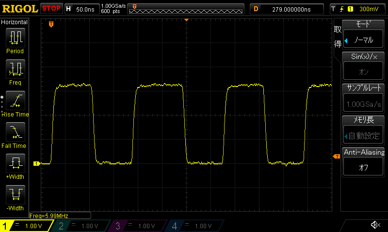
Use Registers
You can also create a pulse by directly operating the register without using digitalWrite.
void setup() {
  pinMode(PIN_A7, OUTPUT);
}

#define P                                                             \
  digitalPinToPort(PIN_A7)->OUTSET.reg = digitalPinToBitMask(PIN_A7); \
  digitalPinToPort(PIN_A7)->OUTCLR.reg = digitalPinToBitMask(PIN_A7);

#define W P P P P P P P P P P P P P P P P
void loop() { W W W W W W W W W W W W W W W W }
Use Single Cycle IOBUS
We use IOBUS.h introduced here.
#include "IOBUS.h"

#define digitalPinToIOPin(P) ((g_APinDescription[P].ulPort << 5) + g_APinDescription[P].ulPin)
#define PIN_NUM digitalPinToIOPin(PIN_A7)

void setup() {
  IOBUS::pinMode(PIN_NUM, OUTPUT, true);
}

#define P IOBUS::toggleOutput(PIN_NUM);

#define W P P P P P P P P P P P P P P P P
void loop() { W W W W W W W W W W W W W W W W }
| DigitalWrite | Registers | Single Cycle IOBUS | |
|---|---|---|---|
| Waveform |
|
|
|
| frequency | 333 kHz | 6 MHz | 24 MHz |
| Number of clock cycles needed to create a pulse | 144 | 8 | 2 |
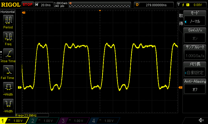
The logic can be certainly reversed in one cycle (48MHz).
Tech Support & Product Discussion
Thank you for choosing our products! We are here to provide you with different support to ensure that your experience with our products is as smooth as possible. We offer several communication channels to cater to different preferences and needs.