Getting Started with the S2100 and a 12V RS485 Sensor
This guide will help you get started with the S2100 and a 12V RS485 sensor. After completing this, you’ll understand how to connect your own customized sensor in the future.
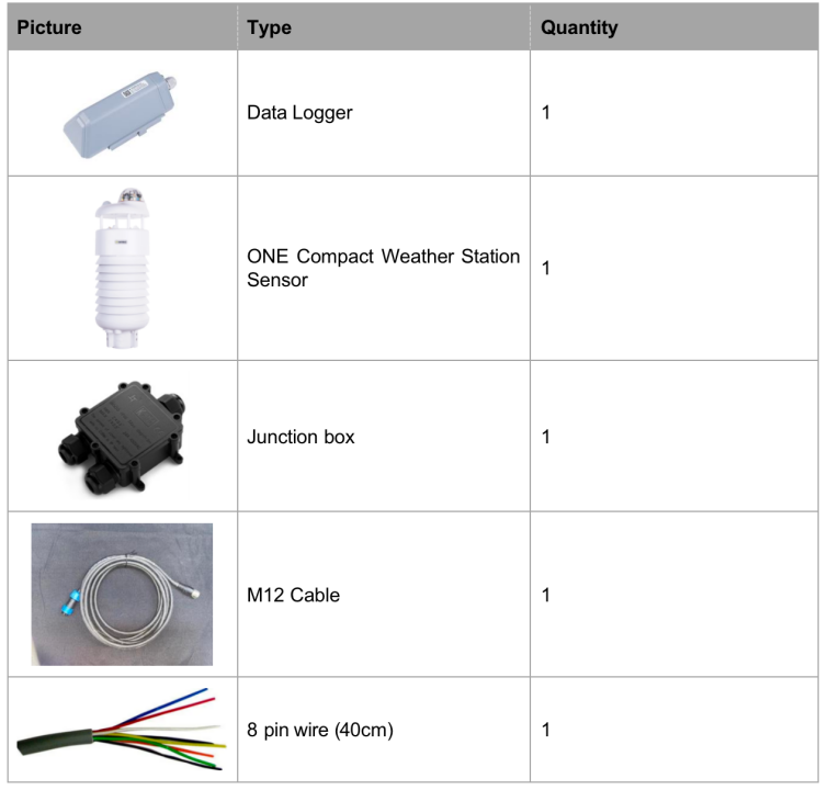
Step 1: Gather Necessary Items
- Data Logger
- ONE Compact Weather Station Sensor (as an example)
- Junction box
- M12 cable
- 8-pin wire (40cm)
- Cross screwdriver (Cross recess No.2)
- SenseCAP Mate App
Step 2: Connect the Sensor
Follow the steps below to complete the wiring process.
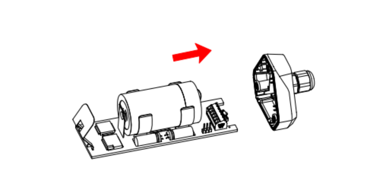
Step 2.1: Disassemble the Data Logger
-
Unscrew the three screws.
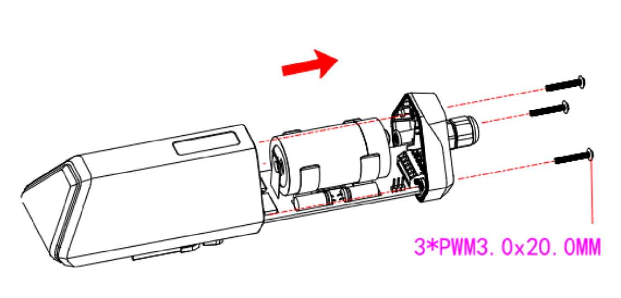
-
Remove the cover.
-
Remove the threaded cap, pass the sensor cable through the cap and the bottom cover, and connect it to the wiring terminal.
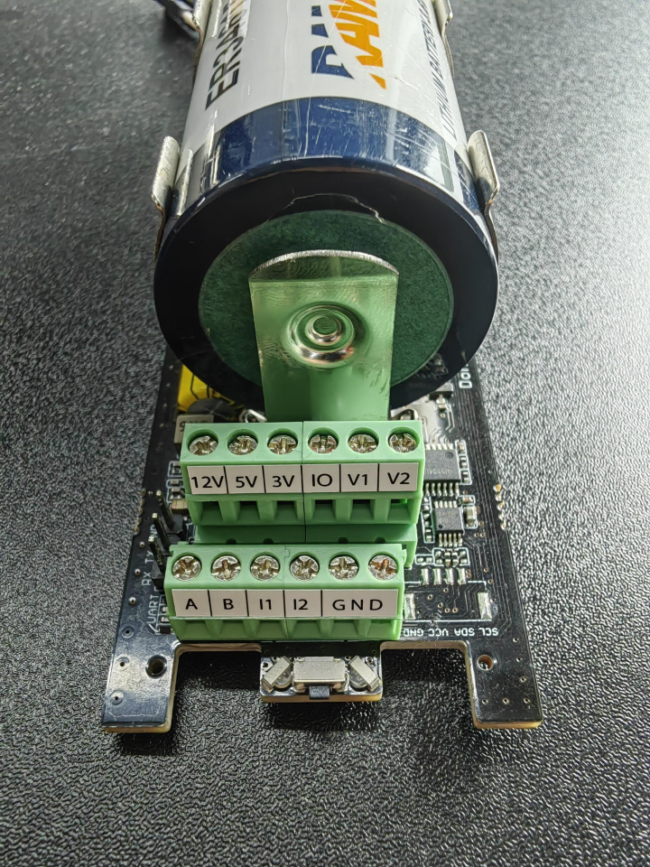
Step 2.2: Wiring Terminal Description
| No. | Pin | Description |
|---|---|---|
| 1 | 12V | External 12V input voltage. The Data Logger can be powered by an external 12V DC power supply. When using a 12V power supply, the battery will serve as a backup power supply. |
| 2 | 5V | 5V output voltage, providing 5V voltage to the sensor. |
| 3 | 3V | 3V output voltage, providing 3V voltage to the sensor. |
| 4 | IO | Acquisition level or pulse input. |
| 5 | V1 | Voltage input of 0 to 10V is collected. |
| 6 | V2 | Voltage input of 0 to 10V is collected. |
| 7 | A | RS485 A/+ |
| 8 | B | RS485 B/- |
| 9 | I1 | Collect the current input from 4 to 20mA. |
| 10 | I2 | Collect the current input from 4 to 20mA. |
| 11 | GND | Ground pin. |
| 12 | GND | Ground pin. |
Step 2.3: Power Supply Options for Sensor
The Data Logger supports two power supply modes. We will use the External 12V DC mode here:
| Mode | Description |
|---|---|
| Built-in Battery | The Data Logger and sensors are powered by batteries. In this case, the Data Logger can be connected to a 5V sensor. |
| External 12V DC | Supply power to the Data Logger and sensor through an external 12V power supply. If the external 12V is disconnected, the system switches to battery power. When using an external 12V power supply, use it together with the junction box to ensure the waterproof performance of the device. |
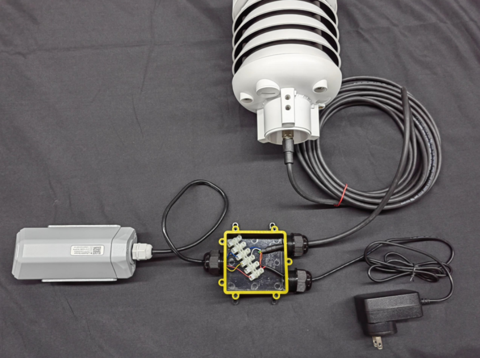
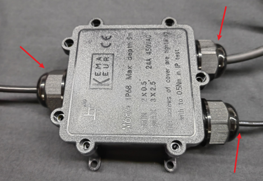
Step 2.4: Connect to the Junction Box
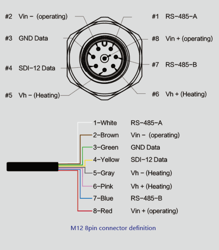
Wire sequence of M12 cable:
When your sensor requires 12V power, the battery alone cannot drive the sensor. Therefore, an external 12V power supply is necessary.
-
Prepare the following items: 12V DC adapter, Junction box, and 8-pin wire (only 4 pins are needed).
-
Wire the terminal of the Data Logger.

Attach the cover, rubber ring, and screw cap in sequence.


-
Wire the terminal of the junction box.

-
Connect the M12 sensor wire to the junction box.

-
Connect the 12V DC adapter to the power supply.
Step 3: Connect to the Sensor
Now that you’ve successfully connected the junction box to the S2100, we’ll move on to connecting the sensor.
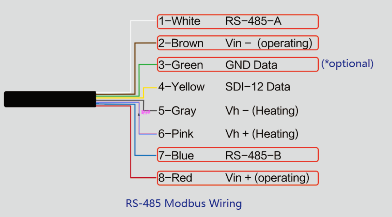
Step 3.1: Learn the Wire Sequence of ONE Compact Weather Station Sensor
The device uses an M12 8-pin connector. The different colored pins provide power and data communication as shown below.
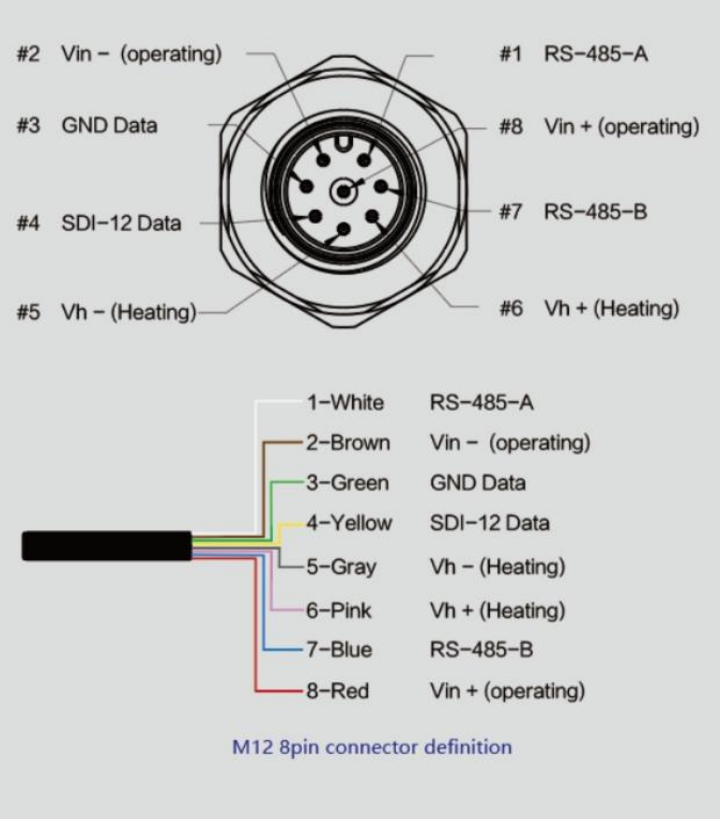
When working with RS-485, you can connect only 4 wires (not using the heating function). The rest should be individually wrapped with tape to prevent short circuits.
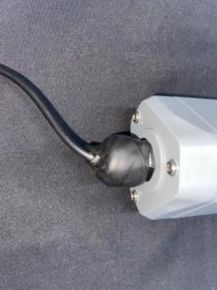
Ensure that the cable holes and device connector pins align correctly when plugging in the cable.
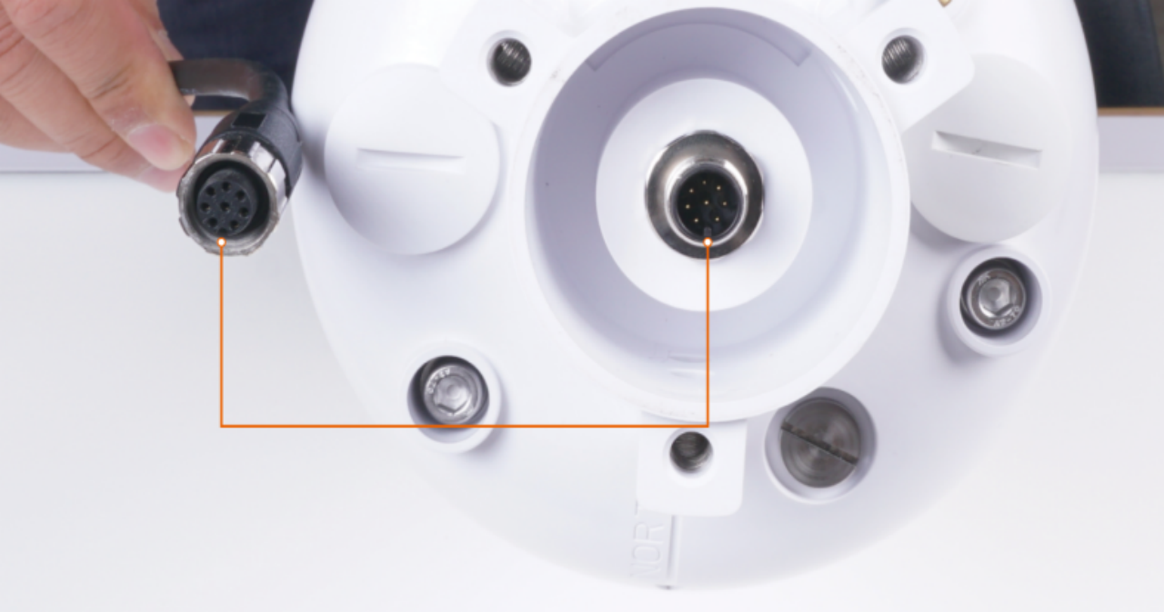
Plug in the cable and tighten it clockwise.
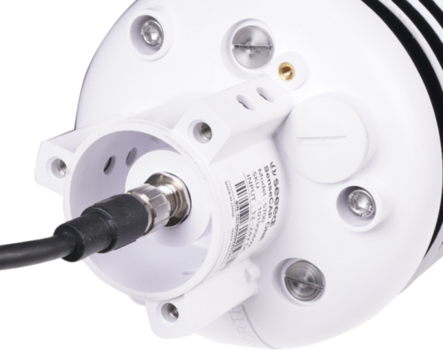
Finally, complete the assembly.
Tighten the screws and screw caps to ensure waterproofing. If the wire diameter is too thin, add waterproof tape for winding.
*Note: When assembling the device, ensure the waterproof pad of the Data Logger and the adapter box is installed, and the screw cap and screws are tightened. Otherwise, the waterproofing of the device may be compromised. If the wire diameter is too small, wrap it with waterproof tape, as shown below:
At this point, the wiring is complete. Now, let’s set up the S2100 and configure it using our app.
Step 4: Setup the S2100
Step 4.1: Connect to the Sensor through the App
-
Press the button and hold for 3 seconds. The LED will flash at a 1s frequency. Use the app to connect to the sensor within 1 minute; otherwise, the device will power off or reboot.

-
Select “S2100 Data Logger”.
Turn on Bluetooth by clicking the “Setup” button, then click “Scan” to start scanning for the sensor's Bluetooth.


-
Select the sensor by S/N (S/N is on the front label of the sensor). The basic information of the sensor will be displayed.


-
Enter configuration mode after the Bluetooth connection is successful. The LED will flash at a 2s frequency.
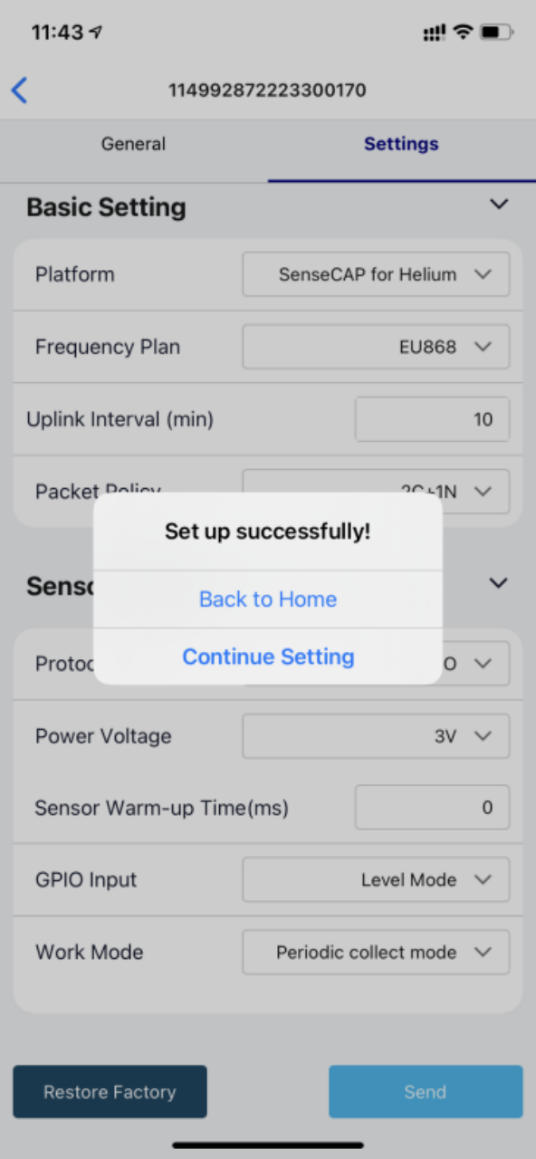
Step 4.2: Configure Basic Parameters through the App
Select the Platform and Frequency
S210x Sensors support a universal frequency plan from 863MHz to 928MHz. Each device can support seven frequency plans.
Here, select either “SenseCAP for Helium” or “SenseCAP for TTN” based on your actual situation.
*Note: The Data Logger can upload data when a Helium network is nearby. It runs on SenseCAP's private Helium Console, so users do not need to create a device on the Helium Console.
The SenseCAP for TTN platform needs to be used with the SenseCAP LoRaWAN outdoor gateway.
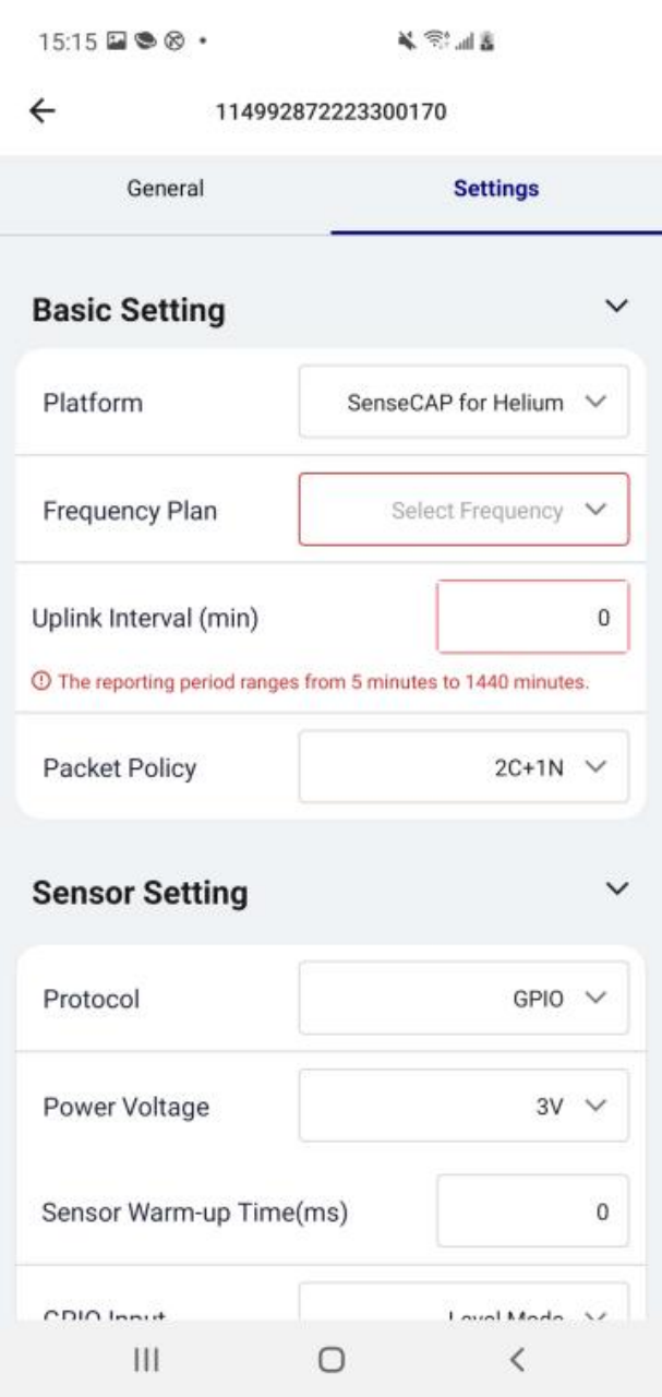
Set the Interval
The device collects and uploads data every 60 minutes by default. You can adjust this interval based on your needs.

Set the Packet Policy
Select the uplink packet strategy based on your requirements. We’ll select 1N here.
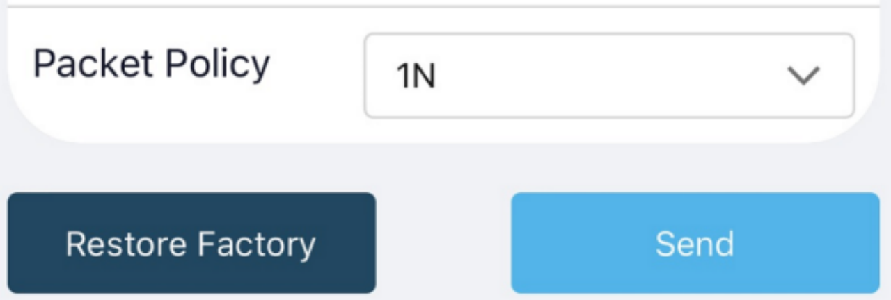
| Parameter | Description |
|---|---|
| 2C+1N (default) | 2C+1N (2 confirm packets and 1 none-confirm) minimizes packet loss, but consumes the most data packets in TTN or data credits in the Helium network. |
| 1C | 1C (1 confirm) will cause the device to sleep after receiving 1 confirmed packet from the server. |
| 1N | 1N (1 none-confirm) will send the packet and then start to sleep, regardless of whether the server received the data. |
Restore Factory Settings
If you are switching back to the SenseCAP platform from other platforms, restore the factory settings. This resets the device's basic settings.

Step 4.3: Configure RS485 Modbus-RTU Sensor via App
Select “Protocol” as “RS485 Modbus RTU” and set the following parameters in turn.
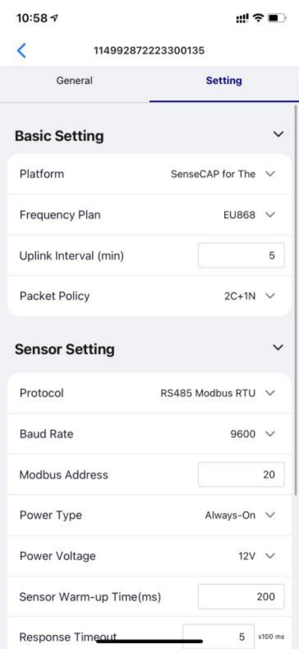
| Baud Rate | Baud rate of communication with the sensor. Select 9600. |
|---|---|
| Modbus Address | The default address is 10 for Five in ONE, 20 for Seven in ONE, 38 for Nine in ONE, and 43 for Ten in ONE. Slave address of the sensor ranges from 1 to 247. Enter 20 here. |
| Power Type | Select Always on. Periodic power reduces power consumption and increases battery life by powering the sensor only before data collection. |
| Power Voltage | Select the supply 12V voltage to the sensor. |
| Sensor Warm-up Time | The time it takes for the sensor to attain its highest accuracy or performance level after power is applied. Enter 200ms. |
| Response Timeout | Time the Data Logger waits for a response after sending a data read request to the sensor. If exceeded, the command will be resent. 5(*100ms) is suitable. |
| Startup Time | Time for the sensor to start communicating with Modbus after being powered on. 10*(100ms) is suitable. |
| Measurement Number | Collect 0 to 10 measurements in RS485 mode. Since the sensor has seven kinds of sensor registers, select 7. |
| Work Mode | Select Periodic collect mode: Periodically collect and upload data. |
| Measurement Setting | Set the register of the measurement value and other configurations. |
Measurement Setting
Set each measurement in turn. Measurement1 (Air temperature)
| Register Address | The register address of the measured value in the sensor, which is an integer. The Air temperature register address is 0.Enter 0 here. |
|---|---|
| Function Code | Modbus function code, select 03 here. |
| Data Type | The data type determines the number of registers read from the sensor and how the data should parse the value. Select Signed 32bit integer, 0xABCD here. |
| Precision | Precision of the value. You can choose the decimal place of the measurement value. If 1 is selected, one decimal place is reserved. Select 2, #.## here. |
| Y= Ax + B | “Y”: It is the value of Data Logger will upload. “x”: It is the original current value. Factory A: Custom values that can be scaled up or down by multiples of the “x”. Factory B: A custom value that increments or diminishes the value of the “x”. By setting the values of A and B, you can calculate the desired value. If only raw values are uploaded, set A=1 and B=0. Factory A is 0.001 and Factory B is 0. |
| Write Strategy | This function is enabled only for some special sensors and is generally disabled by default After reading the value of the register, special instructions can be issued to the sensor, such as the instruction to empty the register after reading register 0. None: Off by default. After Read: Send the RS485 command to sensor after reading the register. On New Data: Send the RS485 command to sensor every 24 hours. We don’t need to write strategy so we select None here. |
Measurement2 (Air humidity)
| Register Address | Enter 2 here. |
|---|---|
| Function Code | Select 03 here. |
| Data Type | Select Signed 32bit integer, 0xABCD here. |
| Precision | Select 2, #.## here. |
| Y= Ax + B | Factory A is 0.001 and Factory B is 0. |
| Write Strategy | We don’t need to write strategy so we select None here. |
Measurement3 (Barometric pressure)
| Register Address | Enter 4 here. |
|---|---|
| Function Code | Select 03 here. |
| Data Type | Select Signed 32bit integer, 0xABCD here. |
| Precision | Select 0, # here. |
| Y= Ax + B | Factory A is 0.001 and Factory B is 0. |
| Write Strategy | We don’t need to write strategy so we select None here. |
Measurement4 (Light intensity)
| Register Address | Enter 6 here. |
|---|---|
| Function Code | Select 03 here. |
| Data Type | Select Signed 32bit integer, 0xABCD here. |
| Precision | Select 0, # here. |
| Y= Ax + B | Factory A is 0.001 and Factory B is 0. |
| Write Strategy | We don’t need to write strategy so we select None here. |
Measurement5 (Average wind direction)
| Register Address | Enter 12 here. |
|---|---|
| Function Code | Select 03 here. |
| Data Type | Select Signed 32bit integer, 0xABCD here. |
| Precision | Select 1, #.# here. |
| Y= Ax + B | Factory A is 0.001 and Factory B is 0. |
| Write Strategy | We don’t need to write strategy so we select None here. |
Measurement6 (Average wind speed)
| Register Address | Enter 18 here. |
|---|---|
| Function Code | Select 03 here. |
| Data Type | Select Signed 32bit integer, 0xABCD here. |
| Precision | Select 1, #.# here. |
| Y= Ax + B | Factory A is 0.001 and Factory B is 0. |
| Write Strategy | We don’t need to write strategy so we select None here. |
Measurement7 (Rain intensity)
| Register Address | Enter 24 here. |
|---|---|
| Function Code | Select 03 here. |
| Data Type | Select Signed 32bit integer, 0xABCD here. |
| Precision | Select 1, #.# here. |
| Y= Ax + B | Factory A is 0.001 and Factory B is 0. |
| Write Strategy | We don’t need to write strategy so we select None here. |
After configuring these measurements, click "Back to Home". The node and the app Bluetooth will automatically disconnect. The Data Logger will attempt to connect to the network. The LED indicator will flash red slowly while trying to connect and will flash green quickly once the network connection is successful.
Step 5: Check Data on the SenseCAP Portal
Step 5.1: Bind Sensor to SenseCAP Portal
Open the SenseCAP Mate App.
-
Scan QR Code: Click "Add device" in the upper-right corner of the device page to enter the device binding page.

-
Scan the QR code on the device to bind it to your account. If you do not set it to a designated group, the device will be put into the "default" group.

-
Manually fill in the EUI: If the QR code sticker is damaged, you can manually fill in the EUI of the device to bind it to your account. Ensure the EUI is entered in the format suggested by the system, then click "confirm".


Step 5.2: Check Data on SenseCAP Portal
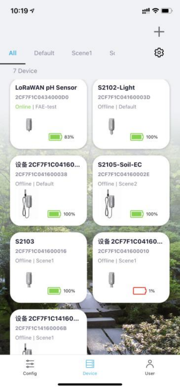
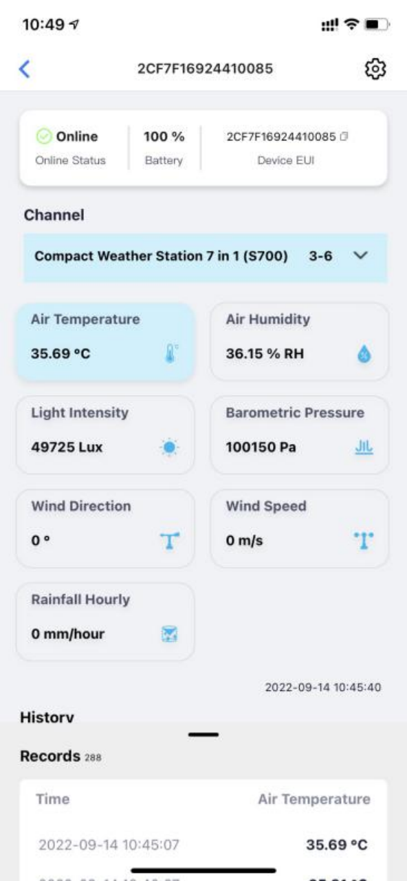
On the SenseCAP Mate App or the SenseCAP Portal, you can check the device's online status and the latest data. The list for each sensor will show its online status and the time of its last data upload.
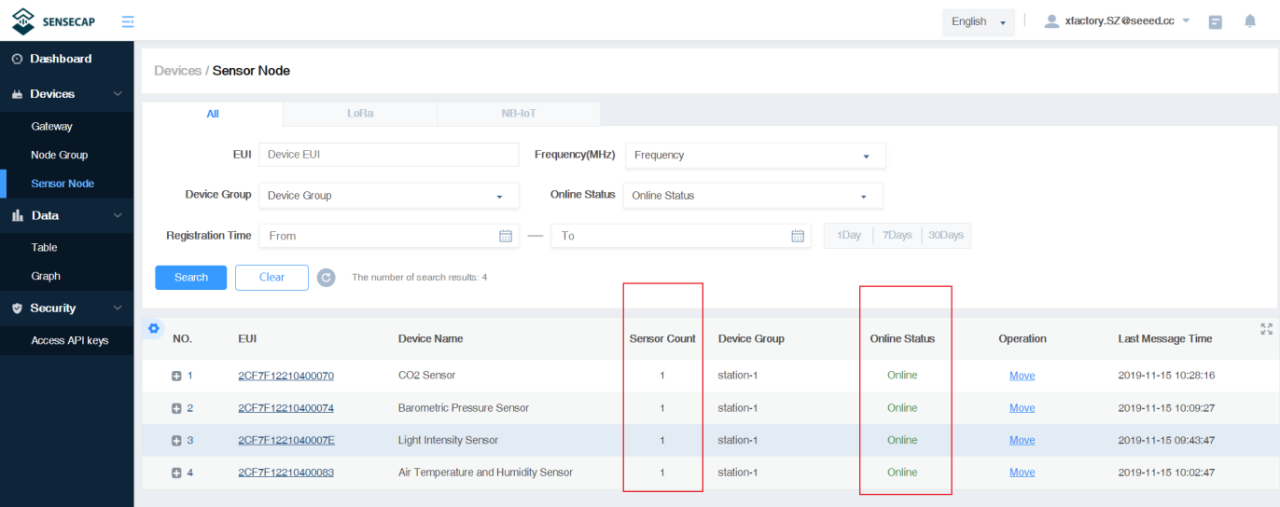
You can also check the data on the SenseCAP Mate App.