Wio Terminal Edge Impulse Audio Scene Recognition with Built-in Microphone
In this project we will learn how to train and deploy an audio scene classifier with Wio Terminal and Edge Impulse. For more details and video tutorial, watch the corresponding video!
Sound processing in computers
Audio scene classification is a task, where machine learning model needs to predict a class for audio segment, for example, "a crying baby", "a cough", "a dog barking", etc.
Sound is an a vibration that propagates (or travels) as an acoustic wave, through a transmission medium such as a gas, liquid or solid.
The source of sound pushes the surrounding medium molecules, they push the molecules next to them and so on and so forth. When they reach other object it also vibrates slightly – we use that principle in microphone. The microphone membrane gets pushed inward by the medium molecules and then back to its original position.
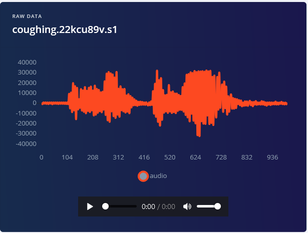
That generates alternating current in the circuit, where voltage is proportional to sound amplitude – the louder the sound, the more it pushes membrane, thus generating higher voltage. We then read this voltage with analog-to-digital converter and record at equal intervals – the number of times we take measurement of sound in one second is called a sampling rate, for example 8000 Hz sampling rate is taking measurement 8000 times per second. Sampling rate obviously matters a lot for quality of the sound – if we sample too slow we might miss important bits and pieces. The numbers used for recording sound digitally also matter – the larger range of a number used, the more “nuances” we can preserve from the original sound. That is called audio bit depth – you might have heard terms like 8-bit sound and 16-bit sound. Well, it is exactly what is says on the tin – for 8-bit sound an unsigned 8-bit integers are used, which have range from 0 to 255. For 16-bit sound a signed 16-bit integers are used, so that’s -32768 to 32767. Alright, so in the end we have a string of numbers, with larger numbers corresponding to loud parts of the sound and we can visualize it like this - this is 1 second of gunshot sound recorded at 8000 Hz frequency in 8-bit depth (0-255).

We can’t do much with this raw sound representation though – yes, we can cut and paste the parts or make it quilter or louder, but for analyzing the sound, it is, well, too raw. Here is where Fourier transform, Mel scale, spectrograms and cepstrum coefficients come in. For purpose of this project, we’ll define Fourier transform as a mathematical transform, that that allows us to decompose a signal into it’s individual frequencies and the frequency’s amplitude.
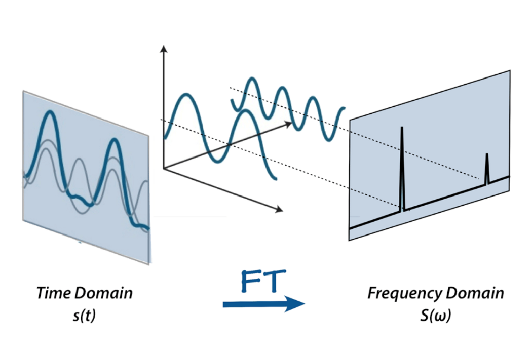
Or, if you'd like to use a metaphor – given the smoothie, it outputs the recipe.
There is a lot of materials on the Internet about Fourier transform, for example this article from betterexplained.com and a video from 3Blue1Gray – check them out to find more about FFT.
That is how our sound looks like after applying Fourier transform – the higher bars correspond to larger amplitude frequencies.

That’s great! Now we can do more interesting things with audio signal – for example eliminate the least important frequencies to compress the audio file or remove the noise or maybe the sound of voice, etc. But it is still not good enough for audio and speech recognition – by doing Fourier transform we lose all the time domain information, which is not good for non-periodic signals, such as human speech. We are smart cookies though and just take Fourier transform multiple times on the signal sample, essentially slicing it and then stitching the data from multiple Fourier transforms back together in form of spectrogram.
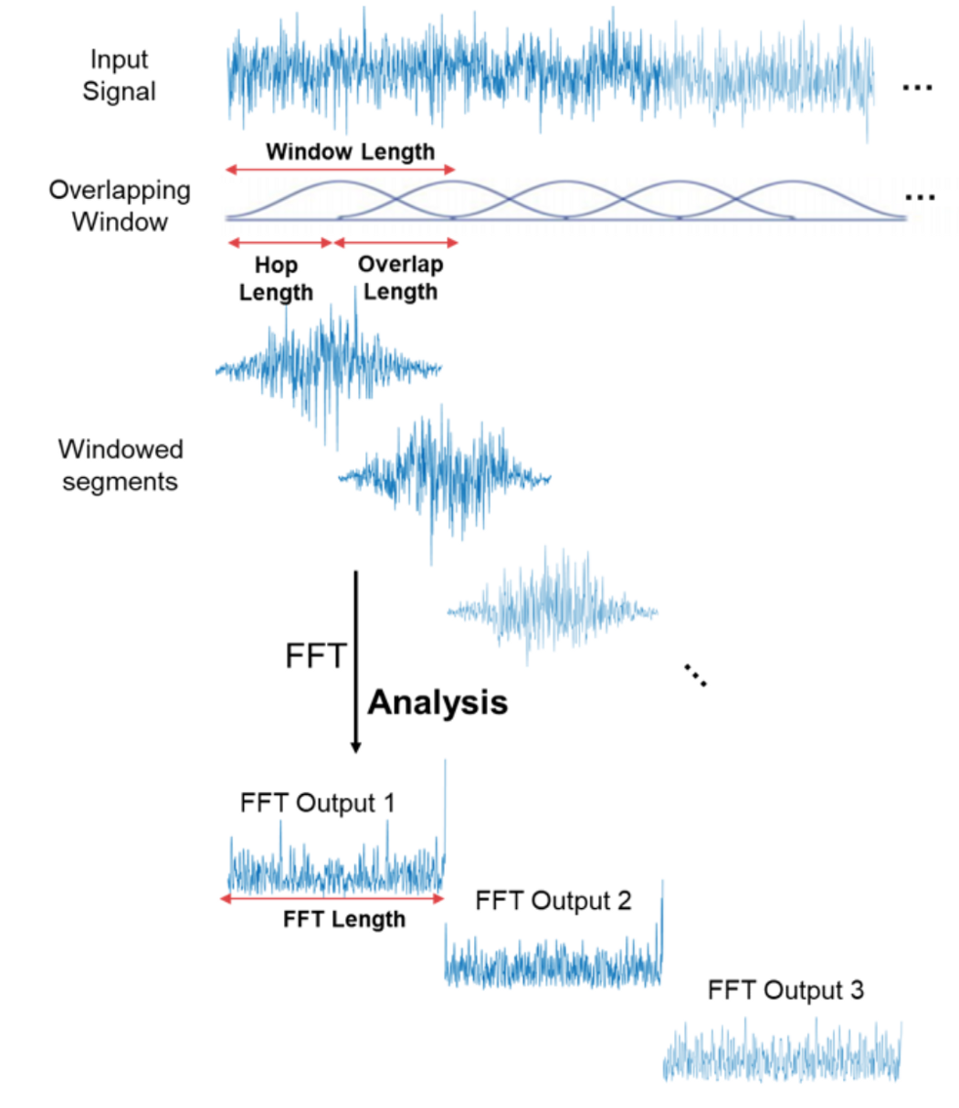
Here x-axis is the time, y-axis is frequency and the amplitude of a frequency is expressed through a color, brighter colors correspond to larger amplitude.

Very well! Can we do sound recognition now? No! Yes! Maybe! Normal spectrogram contains too much information if we only care about recognizing sounds that human ear can hear. Studies have shown that humans do not perceive frequencies on a linear scale. We are better at detecting differences in lower frequencies than higher frequencies. For example, we can easily tell the difference between 500 and 1000 Hz, but we will hardly be able to tell a difference between 10000 and 10500 Hz, even though the distance between the two pairs are the same. In 1937, Stevens, Volkmann, and Newmann proposed a unit of pitch such that equal distances in pitch sounded equally distant to the listener. This is called the mel scale.
A mel spectrogram is a spectrogram where the frequencies are converted to the mel scale.

There are more steps involved for recognizing speech – for example cepstrum coefficients, that we mentioned above – we will discuss them in later projects. It is time to finally start with practical implementation.
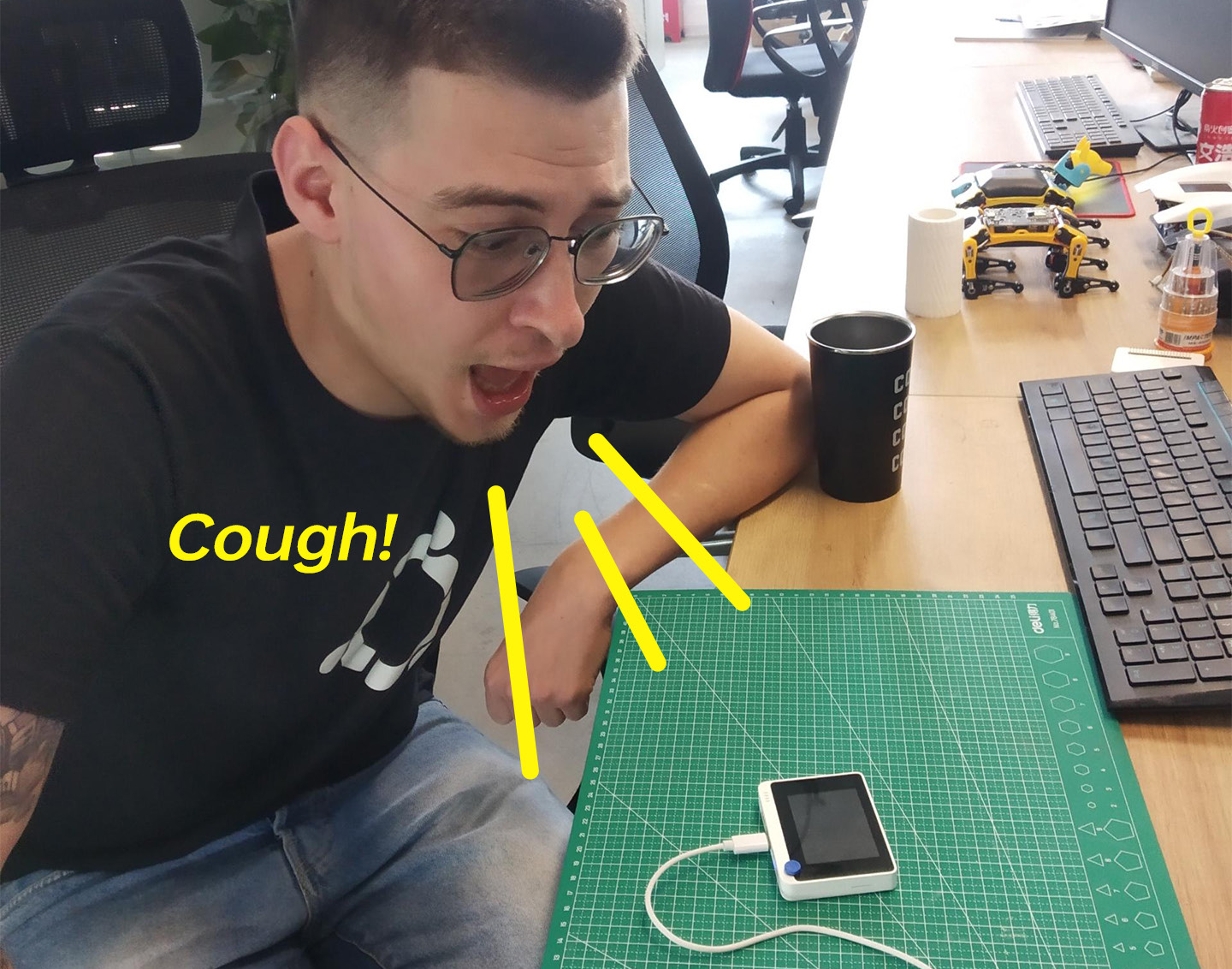
Training data acquisition
Audio signal needs to be sampled at very high sampling rate, 8000 Hz or, ideally, 16000 Hz. Edge Impulse Data Forwarder tool is too slow to handle this sampling rate, so we will need to use dedicated data collection firmware to get the data for this project. Download a new version of Wio Terminal Edge Impulse firmware with microphone support and flash it to your device, as described on Getting started with Edge Impulse page. After that create a new project on Edge Impulse platform, launch edge-impulse ingestion service
edge-impulse-daemon
If you used edge-impulse-daemon before, you will need to add --clean to the command above to clean project data.
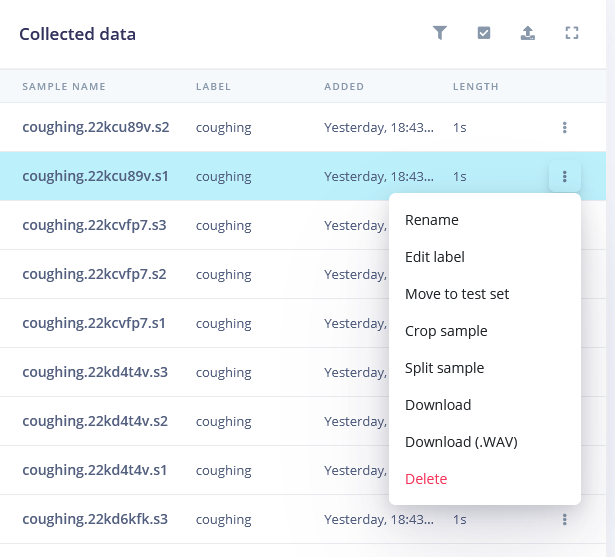
Then log in with your credentials and choose a project you have just created. Go to Data Acquisition tab and you can start getting data samples.
We will have three classes of data:
• background
• coughing
• crying
Record 10 samples for each class, 5000 milliseconds duration each. You can recording the sounds played from the computer speakers (except for background class), but if you have the opportunity to record real sounds, that would be even better.
For background class record sounds that should not be classified as coughing or crying, e.g. people talking, no sounds, air conditioning/fan and so on and so forth.
30 samples is abysmally small, so we’re also going to upload some more data. Simply download the sounds from the Internet, resample them to 16000 Hz and save them to .wav format with this converter script
import librosa
import sys
import soundfile as sf
input_filename = sys.argv[1]
output_filename = sys.argv[2]

data, samplerate = librosa.load(input_filename, sr=16000)
print(data.shape, samplerate)
sf.write(output_filename, data, samplerate, subtype='PCM_16')
Copy the code and paste it in a text document (use Notepad++, IDLE IDE or other suitable IDE. Do not use Windows default Notepad).
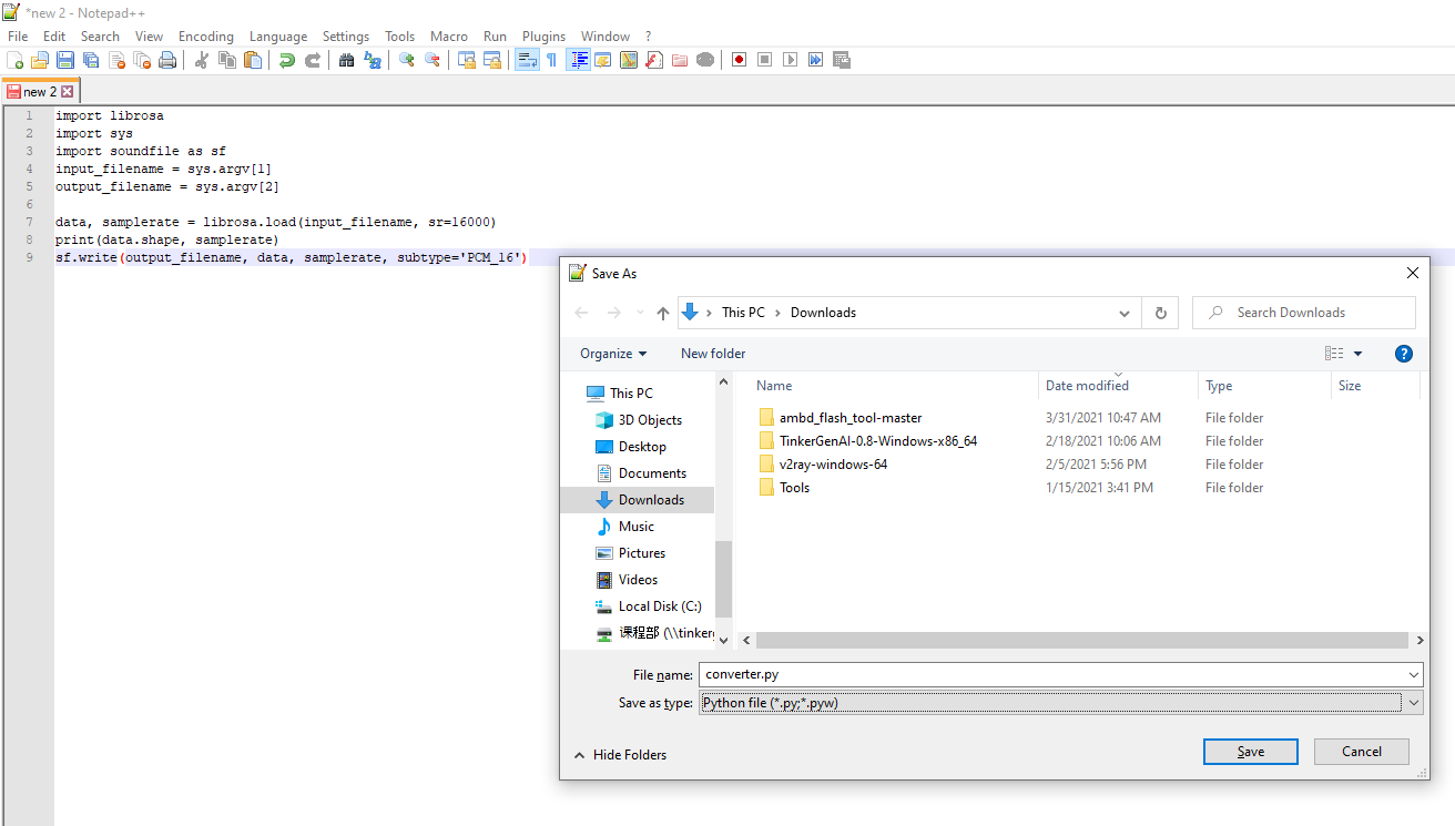
Save document as converter.py and then from Anaconda environment run
python converter.py name-of-the-downloaded-file class_name.number.wav
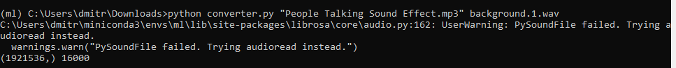
You can find example sound files already converted to right format in Github repository for this project. Then split all the sound samples to leave only “interesting” pieces – do that for every class, except for background.
After the data collection is done, it is time to choose processing blocks and define our neural network model.
Building a machine learning model
Among the processing blocks we see three familiar options – namely Raw, Spectral Analysis, which is essentially Fourier transform of the signal, Spectrogram and MFE (Mel-Frequency Energy banks) – which correspond to four stages of audio processing we described earlier!
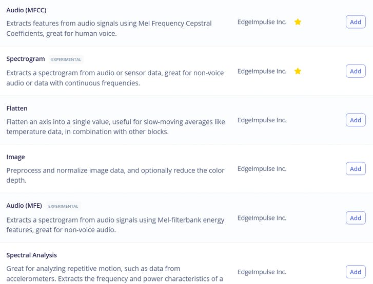
If you like experimenting, you can try using all of them on your data, except for maybe Raw, which will have too much data for our small-ish neural network. For the purpose of this lesson we will just go with the best option for this task, which is MFE or Mel-Frequency Energy banks. After computing the features, go to NN classifier tab and choose a suitable model architecture. The two choices we have are using 1D Conv and 2D Conv. Both will work, but If possible, we should always go for smaller model, since we will want to deploy it to embedded device. When writing the materials for this course we ran 4 different experiments, 1D Conv/2D Conv with MFE and MFCC features and the results for them are in this table.

The best model was 1D Conv network with MFE processing block. By tweaking MFE parameters (namely increasing stride to 0.02 and decreasing low frequency to 0) we have achieved accuracy of 89.4% on validation dataset.
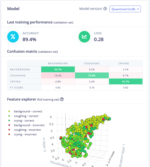
You can find the trained model here and test it out yourself. While it is good at distinguishing crying sounds from background, coughing sound detection accuracy is a bit low low and might require obtaining more samples.
Deploying to Wio Terminal
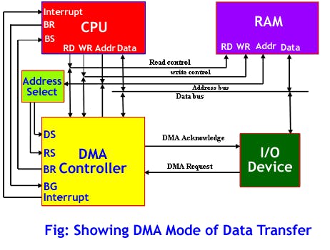
After we have our model and satisfied with its accuracy in training, we can test it on new data in Live classification tab and then Deploy it to Wio terminal. We’ll download it as Arduino library, put it in Arduino libraries folder and open Examples -> name of your project -> nano_33_ble_sense_microphone_continuous. The demo is based on Arduino Nano 33 BLE and uses PDM library. For Wio Terminal we will rely on DMA or Direct Memory Access controller to obtain samples from ADC (Analog to Digital Converter) and save them to inference buffer without involvement of MCU.
That will allow us to collect the sound samples and perform inference at the same time. There is quite a few changes we need to make in order to change sound data collection from PDM library to DMA, if you feel a bit lost during the explanation, have a look at the full sample code, which you can find in the course materials. Delete PDM library from the sketch
#include <PDM.h>
Add DMA descriptor structure, and other settings constants right after last include statement
// Settings
#define DEBUG 1                 // Enable pin pulse during ISR
enum {ADC_BUF_LEN = 4096};    // Size of one of the DMA double buffers
static const int debug_pin = 1; // Toggles each DAC ISR (if DEBUG is set to 1)

// DMAC descriptor structure
typedef struct {
  uint16_t btctrl;
  uint16_t btcnt;
  uint32_t srcaddr;
  uint32_t dstaddr;
  uint32_t descaddr;
} dmacdescriptor;
Then right before setup function create variables for buffer arrays, volatile variables for passing the values between ISR callback and the main code and also High pass Butterworth filter, which we will apply to signal to eliminate most of DC component in microphone signal.
// Globals - DMA and ADC
volatile uint8_t recording = 0;
volatile boolean results0Ready = false;
volatile boolean results1Ready = false;
uint16_t adc_buf_0[ADC_BUF_LEN];    // ADC results array 0
uint16_t adc_buf_1[ADC_BUF_LEN];    // ADC results array 1
volatile dmacdescriptor wrb[DMAC_CH_NUM] __attribute__ ((aligned (16)));          // Write-back DMAC descriptors
dmacdescriptor descriptor_section[DMAC_CH_NUM] __attribute__ ((aligned (16)));    // DMAC channel descriptors
dmacdescriptor descriptor __attribute__ ((aligned (16)));                         // Place holder descriptor

//High pass butterworth filter order=1 alpha1=0.0125
class  FilterBuHp1
{
  public:
    FilterBuHp1()
    {
      v[0]=0.0;
    }
  private:
    float v[2];
  public:
    float step(float x) //class II
    {
      v[0] = v[1];
      v[1] = (9.621952458291035404e-1f * x)
         + (0.92439049165820696974f * v[0]);
      return
         (v[1] - v[0]);
    }
};

FilterBuHp1 filter;
Add three blocks of code after that - the first one is a callback function, called by ISR (Interrupt Service Routine) every time one of the two buffers filled. Inside that function we read elements from recording buffer (the one that was filled just now), process them and put into an inference buffer.
/*******************************************************************************
 * Interrupt Service Routines (ISRs)
 */

/**
 * @brief      Copy sample data in selected buf and signal ready when buffer is full
 *
 * @param[in]  *buf  Pointer to source buffer
 * @param[in]  buf_len  Number of samples to copy from buffer
 */
static void audio_rec_callback(uint16_t *buf, uint32_t buf_len) {

  static uint32_t idx = 0;

  // Copy samples from DMA buffer to inference buffer
  if (recording) {
    for (uint32_t i = 0; i < buf_len; i++) {

      // Convert 12-bit unsigned ADC value to 16-bit PCM (signed) audio value
      inference.buffers[inference.buf_select][inference.buf_count++] = filter.step(((int16_t)buf[i] - 1024) * 16);
      // Swap double buffer if necessary
      if (inference.buf_count >= inference.n_samples) {
        inference.buf_select ^= 1;
        inference.buf_count = 0;
        inference.buf_ready = 1;
      }
    }
  }
}
Next block contains the ISR itself - it is executed by a timer at certain period of time, inside of that function we check if DMAC channel 1 has been suspended - if it has been suspended it means that one of the buffers for microphone data has filled and we need to copy the data from it, switch to another buffer and restart DMAC ADC.
/**
 * Interrupt Service Routine (ISR) for DMAC 1
 */
void DMAC_1_Handler() {

  static uint8_t count = 0;

  // Check if DMAC channel 1 has been suspended (SUSP)
  if (DMAC->Channel[1].CHINTFLAG.bit.SUSP) {

     // Debug: make pin high before copying buffer
#if DEBUG
    digitalWrite(debug_pin, HIGH);
#endif

    // Restart DMAC on channel 1 and clear SUSP interrupt flag
    DMAC->Channel[1].CHCTRLB.reg = DMAC_CHCTRLB_CMD_RESUME;
    DMAC->Channel[1].CHINTFLAG.bit.SUSP = 1;

    // See which buffer has filled up, and dump results into large buffer
    if (count) {
      audio_rec_callback(adc_buf_0, ADC_BUF_LEN);
    } else {
      audio_rec_callback(adc_buf_1, ADC_BUF_LEN);
    }

    // Flip to next buffer
    count = (count + 1) % 2;

    // Debug: make pin low after copying buffer
#if DEBUG
    digitalWrite(debug_pin, LOW);
#endif
  }
}
Next block contains configuration data for ADC DMAC and timer controlling ISR (interrupt Service Routine)
// Configure DMA to sample from ADC at regular interval
void config_dma_adc() {

  // Configure DMA to sample from ADC at a regular interval (triggered by timer/counter)
  DMAC->BASEADDR.reg = (uint32_t)descriptor_section;                          // Specify the location of the descriptors
  DMAC->WRBADDR.reg = (uint32_t)wrb;                                          // Specify the location of the write back descriptors
  DMAC->CTRL.reg = DMAC_CTRL_DMAENABLE | DMAC_CTRL_LVLEN(0xf);                // Enable the DMAC peripheral
  DMAC->Channel[1].CHCTRLA.reg = DMAC_CHCTRLA_TRIGSRC(TC5_DMAC_ID_OVF) |      // Set DMAC to trigger on TC5 timer overflow
                                 DMAC_CHCTRLA_TRIGACT_BURST;                  // DMAC burst transfer

  descriptor.descaddr = (uint32_t)&descriptor_section[1];                     // Set up a circular descriptor
  descriptor.srcaddr = (uint32_t)&ADC1->RESULT.reg;                           // Take the result from the ADC0 RESULT register
  descriptor.dstaddr = (uint32_t)adc_buf_0 + sizeof(uint16_t) * ADC_BUF_LEN;  // Place it in the adc_buf_0 array
  descriptor.btcnt = ADC_BUF_LEN;                                             // Beat count
  descriptor.btctrl = DMAC_BTCTRL_BEATSIZE_HWORD |                            // Beat size is HWORD (16-bits)
                      DMAC_BTCTRL_DSTINC |                                    // Increment the destination address
                      DMAC_BTCTRL_VALID |                                     // Descriptor is valid
                      DMAC_BTCTRL_BLOCKACT_SUSPEND;                           // Suspend DMAC channel 0 after block transfer
  memcpy(&descriptor_section[0], &descriptor, sizeof(descriptor));            // Copy the descriptor to the descriptor section

  descriptor.descaddr = (uint32_t)&descriptor_section[0];                     // Set up a circular descriptor
  descriptor.srcaddr = (uint32_t)&ADC1->RESULT.reg;                           // Take the result from the ADC0 RESULT register
  descriptor.dstaddr = (uint32_t)adc_buf_1 + sizeof(uint16_t) * ADC_BUF_LEN;  // Place it in the adc_buf_1 array
  descriptor.btcnt = ADC_BUF_LEN;                                             // Beat count
  descriptor.btctrl = DMAC_BTCTRL_BEATSIZE_HWORD |                            // Beat size is HWORD (16-bits)
                      DMAC_BTCTRL_DSTINC |                                    // Increment the destination address
                      DMAC_BTCTRL_VALID |                                     // Descriptor is valid
                      DMAC_BTCTRL_BLOCKACT_SUSPEND;                           // Suspend DMAC channel 0 after block transfer
  memcpy(&descriptor_section[1], &descriptor, sizeof(descriptor));            // Copy the descriptor to the descriptor section

  // Configure NVIC
  NVIC_SetPriority(DMAC_1_IRQn, 0);    // Set the Nested Vector Interrupt Controller (NVIC) priority for DMAC1 to 0 (highest)
  NVIC_EnableIRQ(DMAC_1_IRQn);         // Connect DMAC1 to Nested Vector Interrupt Controller (NVIC)

  // Activate the suspend (SUSP) interrupt on DMAC channel 1
  DMAC->Channel[1].CHINTENSET.reg = DMAC_CHINTENSET_SUSP;

  // Configure ADC
  ADC1->INPUTCTRL.bit.MUXPOS = ADC_INPUTCTRL_MUXPOS_AIN12_Val; // Set the analog input to ADC0/AIN2 (PB08 - A4 on Metro M4)
  while(ADC1->SYNCBUSY.bit.INPUTCTRL);                // Wait for synchronization
  ADC1->SAMPCTRL.bit.SAMPLEN = 0x00;                  // Set max Sampling Time Length to half divided ADC clock pulse (2.66us)
  while(ADC1->SYNCBUSY.bit.SAMPCTRL);                 // Wait for synchronization
  ADC1->CTRLA.reg = ADC_CTRLA_PRESCALER_DIV128;       // Divide Clock ADC GCLK by 128 (48MHz/128 = 375kHz)
  ADC1->CTRLB.reg = ADC_CTRLB_RESSEL_12BIT |          // Set ADC resolution to 12 bits
                    ADC_CTRLB_FREERUN;                // Set ADC to free run mode
  while(ADC1->SYNCBUSY.bit.CTRLB);                    // Wait for synchronization
  ADC1->CTRLA.bit.ENABLE = 1;                         // Enable the ADC
  while(ADC1->SYNCBUSY.bit.ENABLE);                   // Wait for synchronization
  ADC1->SWTRIG.bit.START = 1;                         // Initiate a software trigger to start an ADC conversion
  while(ADC1->SYNCBUSY.bit.SWTRIG);                   // Wait for synchronization

  // Enable DMA channel 1
  DMAC->Channel[1].CHCTRLA.bit.ENABLE = 1;

  // Configure Timer/Counter 5
  GCLK->PCHCTRL[TC5_GCLK_ID].reg = GCLK_PCHCTRL_CHEN |        // Enable perhipheral channel for TC5
                                   GCLK_PCHCTRL_GEN_GCLK1;    // Connect generic clock 0 at 48MHz

  TC5->COUNT16.WAVE.reg = TC_WAVE_WAVEGEN_MFRQ;               // Set TC5 to Match Frequency (MFRQ) mode
  TC5->COUNT16.CC[0].reg = 3000 - 1;                          // Set the trigger to 16 kHz: (4Mhz / 16000) - 1
  while (TC5->COUNT16.SYNCBUSY.bit.CC0);                      // Wait for synchronization

  // Start Timer/Counter 5
  TC5->COUNT16.CTRLA.bit.ENABLE = 1;                          // Enable the TC5 timer
  while (TC5->COUNT16.SYNCBUSY.bit.ENABLE);                   // Wait for synchronization
}
Add the debug condition on top of the setup function:
  // Configure pin to toggle on DMA interrupt
#if DEBUG
  pinMode(debug_pin, OUTPUT);
#endif
Then in the setup function, after run_classifier_init(); add the following code that creates inference buffers, configures DMA and starts the recording by setting volatile global variable recording to 1.
  // Create double buffer for inference
  inference.buffers[0] = (int16_t *)malloc(EI_CLASSIFIER_SLICE_SIZE * sizeof(int16_t));

  if (inference.buffers[0] == NULL) {
    ei_printf("ERROR: Failed to create inference buffer 0");
    return;
  }
  inference.buffers[1] = (int16_t *)malloc(EI_CLASSIFIER_SLICE_SIZE *
      sizeof(int16_t));
  if (inference.buffers[1] == NULL) {
    ei_printf("ERROR: Failed to create inference buffer 1");
    free(inference.buffers[0]);
    return;
  }

  // Set inference parameters
  inference.buf_select = 0;
  inference.buf_count = 0;
  inference.n_samples = EI_CLASSIFIER_SLICE_SIZE;
  inference.buf_ready = 0;

  // Configure DMA to sample from ADC at 16kHz (start sampling immediately)
  config_dma_adc();

  // Start recording to inference buffers
  recording = 1;
}
Delete PDM.end(); and free(sampleBuffer); from microphone_inference_end(void) function and also microphone_inference_start(uint32_t n_samples) and pdm_data_ready_inference_callback(void) functions, since we're not using them.
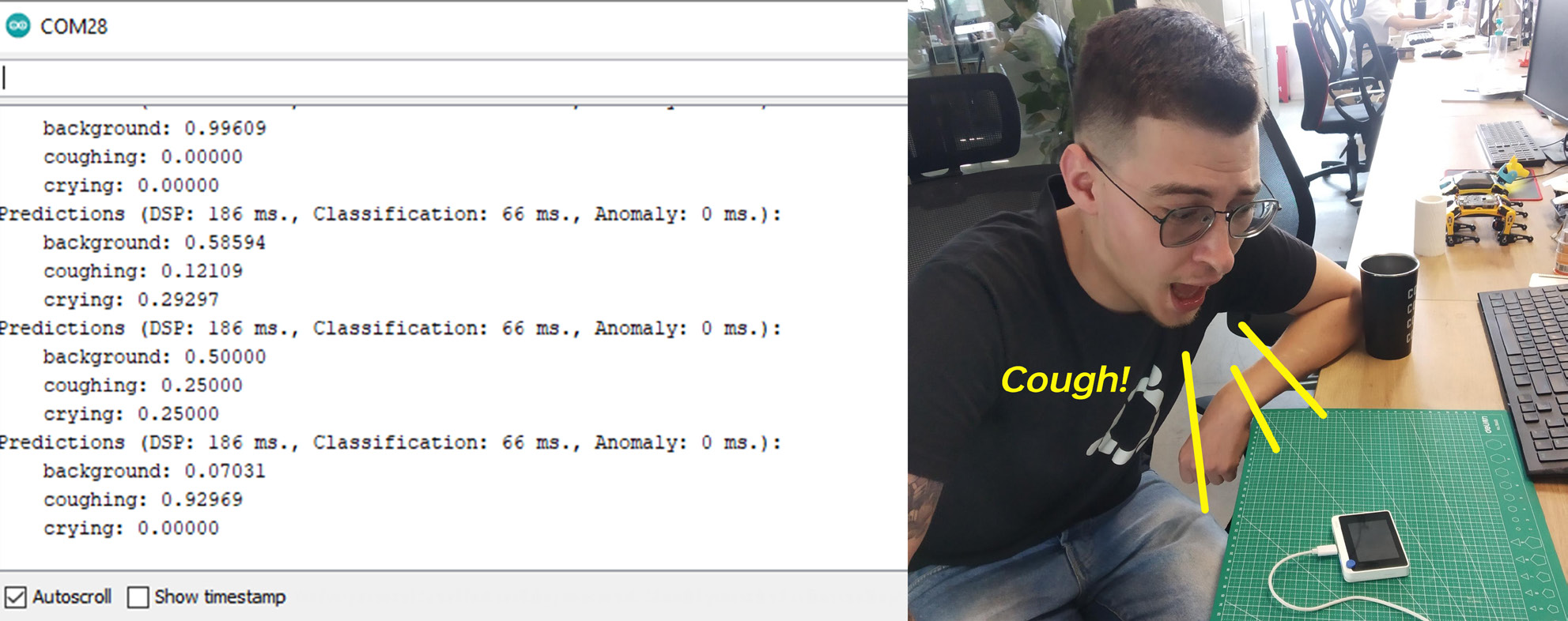
After compiling and uploading the code, open the Serial monitor and you will see probabilities for every classes printed out. Play some sounds or cough at Wio Terminal to check the accuracy!
Blynk integration
Since WioTerminal can connect to the Internet, we can take this simple demo and make it into a real IoT application with Blynk.

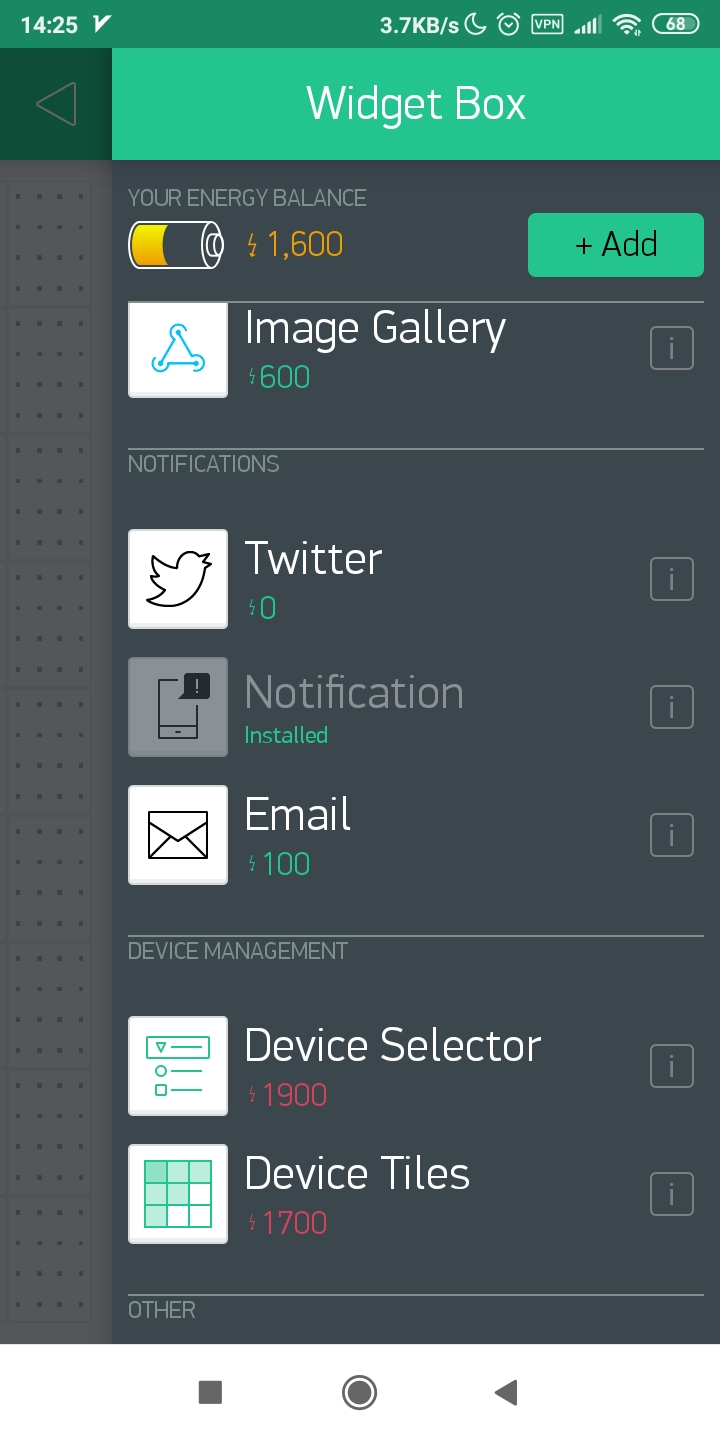
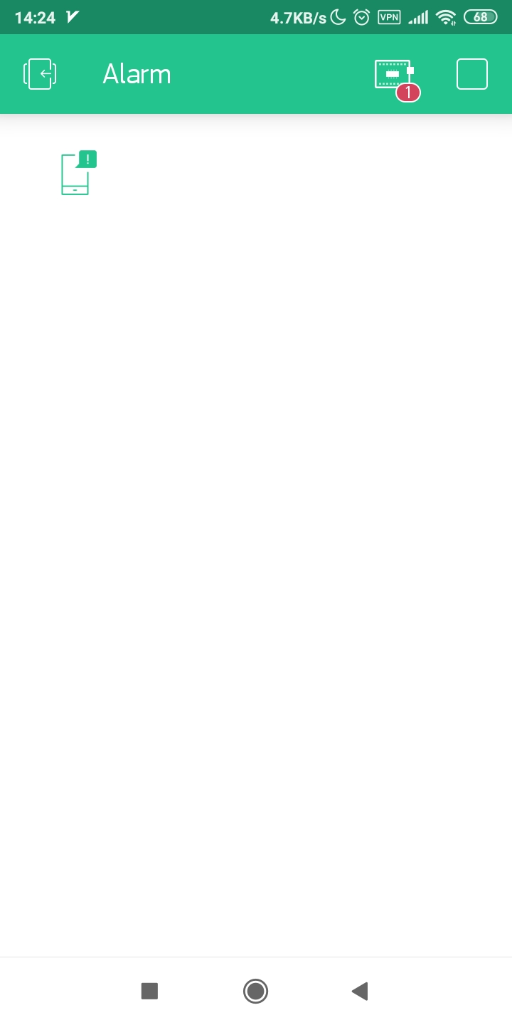
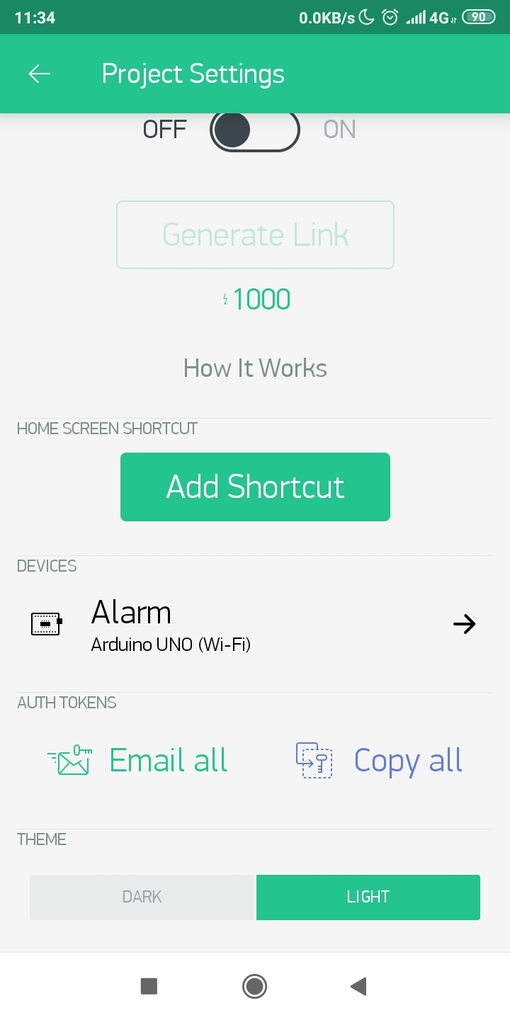
Blynk is a platform that allows you to quickly build interfaces for controlling and monitoring your hardware projects from your iOS and Android devices. In this case we will use Blink to push notification to our smartphone if Wio Terminal detects any sounds we should worry about. To get started with Blink, download the app, register a new account and create a new project. Add a push notification element to it and press play button.
Then make sure you have setup Wio Terminal WiFi libraries and firmware, according to the guide here. Download Blynk library as outlined in that tutorial.
Then test your setup by compiling and uploading simple push button example – make sure you change WiFi SSID, password and your Blynk API token, which you can get in the app.
#define BLYNK_PRINT Serial
#include <rpcWiFi.h>
#include <WiFiClient.h>
#include <BlynkSimpleWioTerminal.h>
char auth[] = "token";
char ssid[] = "ssid";
char pass[] = "password";
void checkPin()
{
int isButtonPressed = !digitalRead(WIO_KEY_A);
if (isButtonPressed) {
Serial.println("Button is pressed.");
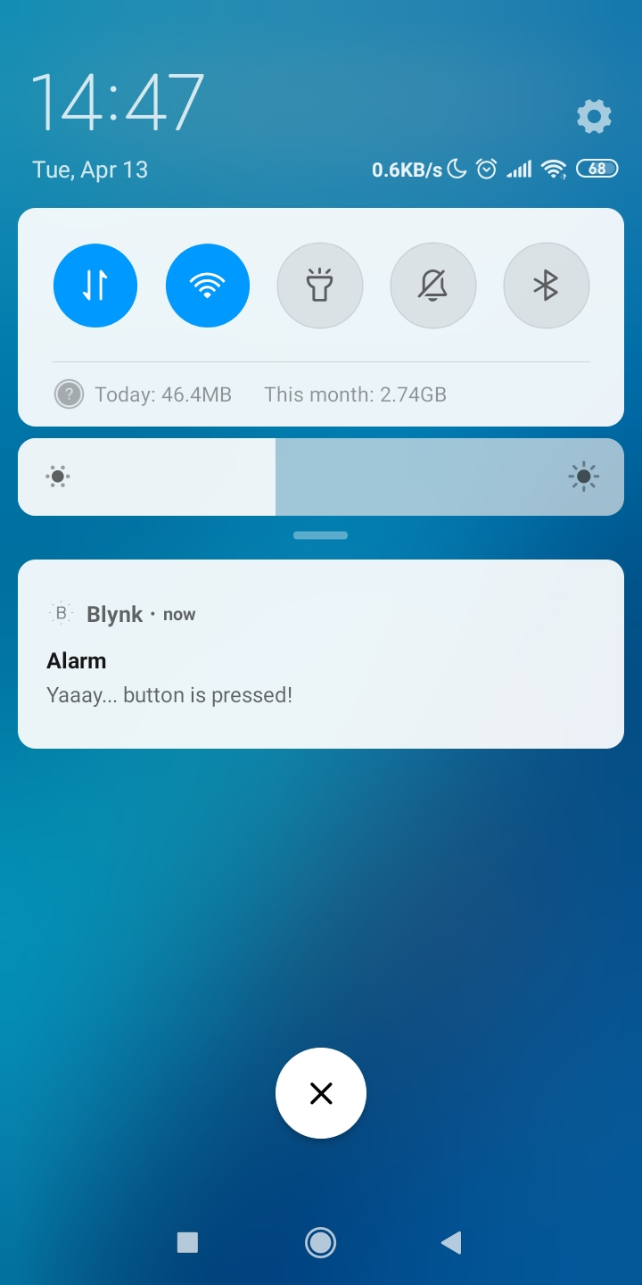
Blynk.notify("Yaaay... button is pressed!");
}
}
void setup()
{
Serial.begin(115200);
Blynk.begin(auth, ssid, pass);
pinMode(WIO_KEY_A, INPUT_PULLUP);
}
void loop()
{
Blynk.run();
checkPin();
}
If code compiles and the test is successful (pressing top left button on Wio Terminal causes a push notification to appear on your phone), then you can move to the next stage.
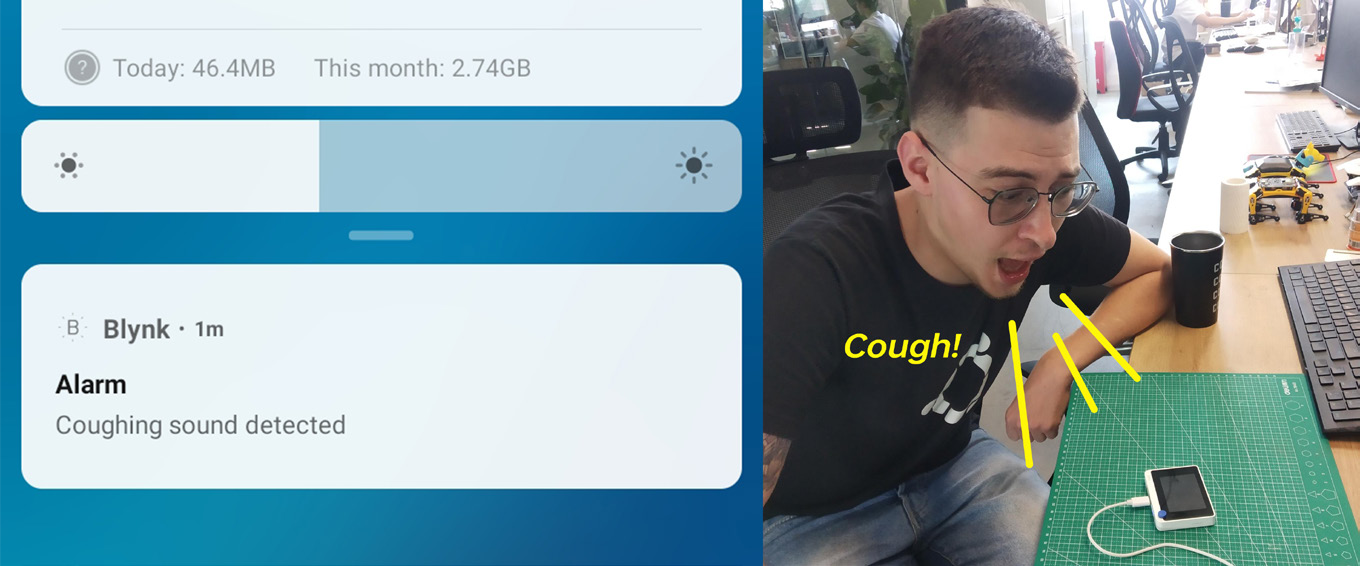
We’re going to move all the neural network inference code in a separate function and call it in the loop() function right after Blynk.run(). Similar to what we did before, we check the neural network prediction probabilities and if they are higher than threshold for a certain class, we call Blynk.notify() function, which as you might have guessed pushes a notification to your mobile device.
Find the full code for NN inference + Blynk notification in Github repository for this project.