Wio Terminal Tensorflow Lite Micro Speech recognition on MCU – Speech-to-Intent
A traditional approach to using speech for device control/user request fulfillment is first, to transcribe the speech to text and then parse the text to the commands/queries in suitable format. While this approach offers a lot of flexibility in terms of vocabulary and/or applications scenarios, a combination of speech recognition model and dedicated parser is not suitable for constrained resources of micro-controllers.
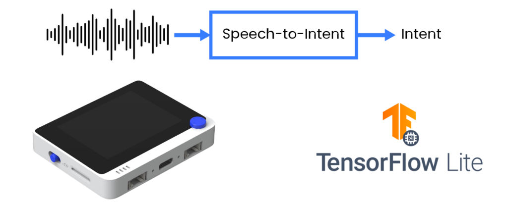
Source: Wio Terminal, Picovoice, Tensorflow Lite
In this project we’re going to employ a more efficient method and directly parse user utterances into actionable output in form of intent/slots. We will share techniques to train a specific domain speech-to-intent model and deploy it to Cortex M4F based development board with built-in microphone, Wio Terminal from Seeed Studio.
For more details and visuals, watch the corresponding video!
There are different types of speech recognition tasks – we can roughly divide them into three groups:
- Large-vocabulary continuous speech recognition (LVCSR)
- Keyword spotting
- Speech-to-Intent
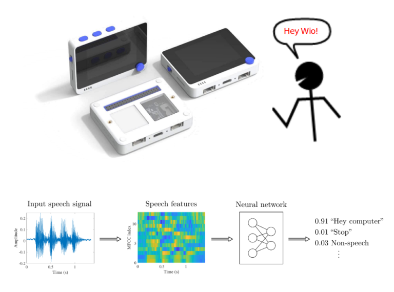
Keyword spotting works well on microcontrollers, fairly easy to train with variety of no-code open-source tools available, e.g. Edge Impulse, but cannot handle large(er) vocabularies well.
If we’d like to have a device to make a useful action based on speech input, we need to combine LVCSR model and text-based Natural language parser – this approach is robust and somewhat easier to implement, given abundance of publicly available ASR engines, but is not suitable for running even on SBCs, let alone microcontrollers.
There is a third way, direct conversion of speech to parsed intent, based on specific domain vocabulary. Let’s take smart washing machine or smart lights as an example. Speech-to-Intent model upon processing utterance “Normal cycle with low-spin” would output parsed intent, for example
{ Intent: washClothes },
{ Slots: cycle: normal,
         spin: low,
         water: default }
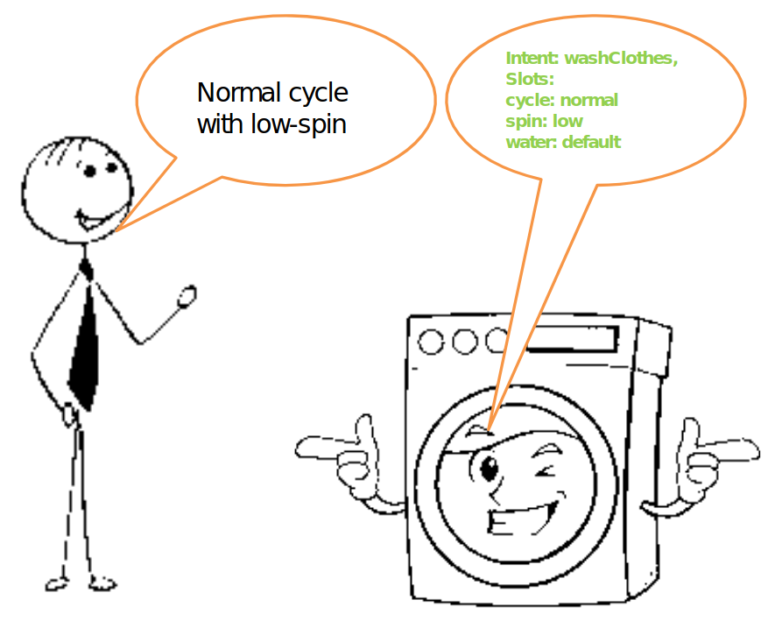
And this is really all what we need to be able to control said smart washing machine with voice.
Speech-to-Intent is well represented in research, but lacking widely available open-source implementations suitable for microcontrollers. Production-ready, not open-source:
- Picovoice
- Fluent.ai
Production-ready, FOSS, not suitable for microcontrollers:
- Speechbrain.io
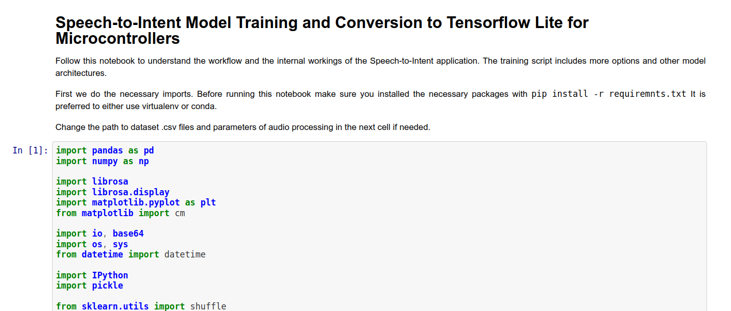
For model training you can use either a Jupyter Notebook we prepared or training scripts from Github repository (find them in the Reference section in the end pf the article). Jupyter Notebook contains a very basic reference model implementation and also has explanation for each cell.
After model is trained copy it to folder with code for Wio Terminal and change the name of the model in line 106 to your model name. Let’s go over the most important pieces of the code. It can be roughly divided into three parts:
- audio acquisition
- MFCC calculation
- inference on MFCC features
Audio acquisition

In order to record sound for processing with Wio Terminal built-in microphone we use DMA ADC function of Cortex M4F MCU. DMA stands for direct memory access and it is exactly what is says on the tin – a specific part of MCU called DMAC or Direct Memory Access Control is set up beforehand to “pipe” the data from one location (e.g. internal memory, SPI, I2C, ADC or other interface) to another. This way the transfer can happen without much involvement from MCU, apart from initial setup. We set the source and destination for transfer here
descriptor.descaddr = (uint32_t)&descriptor_section[1]; // Set up a circular descriptor
descriptor.srcaddr = (uint32_t)&ADC1->RESULT.reg; // Take the result from the ADC0 RESULT register
descriptor.dstaddr = (uint32_t)adc_buf_0 + sizeof(uint16_t) * ADC_BUF_LEN;  // Place it in the adc_buf_0 array
descriptor.btcnt = ADC_BUF_LEN;  // Beat count
descriptor.btctrl = DMAC_BTCTRL_BEATSIZE_HWORD |   // Beat size is HWORD (16-bits)
                      DMAC_BTCTRL_DSTINC |      // Increment the destination address
                      DMAC_BTCTRL_VALID |       // Descriptor is valid
                      DMAC_BTCTRL_BLOCKACT_SUSPEND; // Suspend DMAC channel 0 after block transfer
memcpy(&descriptor_section[0], &descriptor, sizeof(descriptor));  // Copy the descriptor to the descriptor section
descriptor.descaddr = (uint32_t)&descriptor_section[0];           // Set up a circular descriptor
descriptor.srcaddr = (uint32_t)&ADC1->RESULT.reg;                 // Take the result from the ADC0 RESULT register
descriptor.dstaddr = (uint32_t)adc_buf_1 + sizeof(uint16_t) * ADC_BUF_LEN;  // Place it in the adc_buf_1 array
descriptor.btcnt = ADC_BUF_LEN;  // Beat count
descriptor.btctrl = DMAC_BTCTRL_BEATSIZE_HWORD |    // Beat size is HWORD (16-bits)
                      DMAC_BTCTRL_DSTINC |    // Increment the destination address
                      DMAC_BTCTRL_VALID |      // Descriptor is valid
                      DMAC_BTCTRL_BLOCKACT_SUSPEND; // Suspend DMAC channel 0 after block transfer
memcpy(&descriptor_section[1], &descriptor, sizeof(descriptor));  // Copy the descriptor to the descriptor section
As we specify with parameter DMAC_BTCTRL_BLOCKACT_SUSPEND; in DMA descriptor, the DMA Channel should be suspended after a complete block transfer. We then proceed to set up an ISR (Interrupt Service Routine) triggered with the TC5 timer:
 // Configure Timer/Counter 5
GCLK->PCHCTRL[TC5_GCLK_ID].reg = GCLK_PCHCTRL_CHEN | // Enable perhipheral channel for TC5
GCLK_PCHCTRL_GEN_GCLK1;    // Connect generic clock 0 at 48MHz
TC5->COUNT16.WAVE.reg = TC_WAVE_WAVEGEN_MFRQ;     // Set TC5 to Match Frequency(MFRQ) mode
TC5->COUNT16.CC[0].reg = 3000 - 1;                          // Set the trigger to 16 kHz: (4Mhz / 16000) - 1
while (TC5->COUNT16.SYNCBUSY.bit.CC0);                      // Wait for synchronization
// Start Timer/Counter 5
TC5->COUNT16.CTRLA.bit.ENABLE = 1;                          // Enable the TC5 timer
while (TC5->COUNT16.SYNCBUSY.bit.ENABLE);                   // Wait for synchronization
The ISR will call a specific function at equally spaced intervals of time, controlled by TC5 timer. Let’s have a look at that function.
/**
 * Interrupt Service Routine (ISR) for DMAC 1
 */
void DMAC_1_Handler() {

  static uint8_t count = 0;

  // Check if DMAC channel 1 has been suspended (SUSP)
  if (DMAC->Channel[1].CHINTFLAG.bit.SUSP) {

     // Debug: make pin high before copying buffer
#ifdef DEBUG
    digitalWrite(debug_pin, HIGH);
#endif

    // Restart DMAC on channel 1 and clear SUSP interrupt flag
    DMAC->Channel[1].CHCTRLB.reg = DMAC_CHCTRLB_CMD_RESUME;
    DMAC->Channel[1].CHINTFLAG.bit.SUSP = 1;

    // See which buffer has filled up, and dump results into large buffer
    if (count) {
      audio_rec_callback(adc_buf_0, ADC_BUF_LEN);
    } else {
      audio_rec_callback(adc_buf_1, ADC_BUF_LEN);
    }

    // Flip to next buffer
    count = (count + 1) % 2;

    // Debug: make pin low after copying buffer
#ifdef DEBUG
    digitalWrite(debug_pin, LOW);
#endif
  }
}
The ISR function called DMAC1_Handler() checks if DMAC Channel 1 was suspended – which happens when one block of information has finished recording. If it was, it calls a user-defined function audio_rec_callback(), where we copy the content of the filled DMA ADC buffer into a (possibly)larger buffer used to calculate MFCC features. Optionally we also apply some sound post-processing on this step.
MFCC calculation
MFCC feature extraction to match with TensorFlow MFCC Op code is borrowed from ARM repository for Keyword Search on ARM Microcontrollers. You can find the original code here.
Most of the work related to MFCC feature calculation happens within method mfcc_compute(const int16_t audio_data, float mfcc_out) of MFCC class. The method receives a pointer to audio data, in our case 320 sound data points and a pointer to specific position in the array of MFCC output values. For one time slice we do the following operations:
Normalize the data to -1,1 and pad it (in our case the padding does not happen, since the audio data is always the exact size necessary to calculate one slice of MFCC features):
  //TensorFlow way of normalizing .wav data to (-1,1)
  for (i = 0; i < frame_len; i++) {
    frame[i] = (float)audio_data[i]/(1<<15);
  }
  //Fill up remaining with zeros
  memset(&frame[frame_len], 0, sizeof(float) * (frame_len_padded-frame_len));
Calculate RFTT or Real Fast Fourier Transform with ARM Math library function:
  //Compute FFT
  arm_rfft_fast_f32(rfft, frame, buffer, 0);
Convert the values to power spectrum:
  //frame is stored as [real0, realN/2-1, real1, im1, real2, im2, ...]
  int32_t half_dim = frame_len_padded/2;
  float first_energy = buffer[0] * buffer[0],
        last_energy =  buffer[1] * buffer[1];  // handle this special case
  for (i = 1; i < half_dim; i++) {
    float real = buffer[i*2], im = buffer[i*2 + 1];
    buffer[i] = real*real + im*im;
  }
  buffer[0] = first_energy;
  buffer[half_dim] = last_energy;
Then apply Mel filterbanks to square roots of data saved in buffer in the last step. Mel filterbanks are created when MFCC class in instantiated, inside of create_mel_fbank() method. The number of filterbanks, minimum and maximum frequencies are specified by user beforehand – and it is very important to keep them consistent between training script and inference code, otherwise there will be a significant accuracy drop.
  float sqrt_data;
  //Apply mel filterbanks
  for (bin = 0; bin < NUM_FBANK_BINS; bin++) {
    j = 0;
    float mel_energy = 0;
    int32_t first_index = fbank_filter_first[bin];
    int32_t last_index = fbank_filter_last[bin];
    for (i = first_index; i <= last_index; i++) {
      arm_sqrt_f32(buffer[i],&sqrt_data);
      mel_energy += (sqrt_data) * mel_fbank[bin][j++];
    }
    mel_energies[bin] = mel_energy;

    //avoid log of zero
    if (mel_energy == 0.0)
      mel_energies[bin] = FLT_MIN;
  }
Finally we take the discrete cosine transform of the array of Mel energies and write it to MFCC features output array. In the original script a quantization a performed on this step as well, but I opted to use quantization procedure from Tensorflow Lite for Microcontrollers example instead.
Inference on MFCC features
Once all audio within one sample (3 seconds) is processed and converted to MFCC features we convert the whole MFCC feature array from FLOAT32 to INT8 values and feed it to the neural network. TensorFlow Lite for Microcontrollers initialization and inference process was already described in one of my earlier articles, so I won’t repeat it here.
Before you compile the sketch make sure you have all the necessary libraries installed and Seeed SAMD boards definitions are at least 1.8.2 version – that is very important for TensorFlow Lite library to compile without errors. Compile and upload the sketch – if you have DEBUG parameter set to false, code will start running immediately and all you need to do is to press C button on top of the Wio Terminal and say on of the sentences from the dataset. The results will be displayed both on the screen and output to Serial monitor if Wio Terminal is connected to computer.
While this course is based on Wio Terminal, since it is very suitable for exploring Embedded Machine Learning, it is definitely possible to implement it on other devices. The easiest would be to port the code to other Cortex M4F MCU, such as Nano33 BLE Sense – that would only require adjusting for a different microphone. Porting to other ARM MCUs should be fairly trivial too.
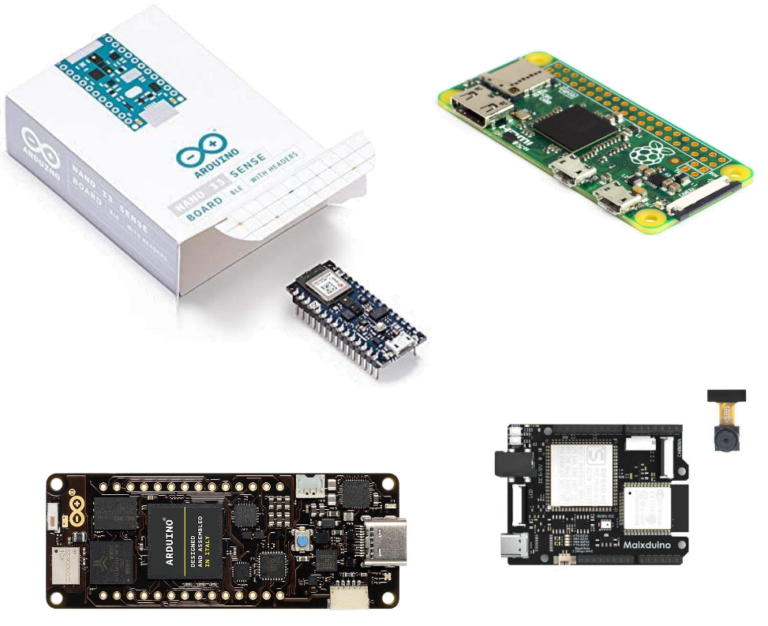
Porting to other architectures, e.g. ESP32 or K210 or others would require re-implementing MFCC calculations, since they use ARM specific functions from CMSIS-DSP.
There are multiple improvements that can be made to basic neural network architectures in the project. These improvements are:
- model pre-training
- seq2seq, LSTM, attention
- trainable filters
- AutoML, synthetic data
Have a look at this TinyML talk on this topic to find out more about this and find links to the papers!
We encourage you to fork the code repository, try training on your own dataset and perhaps try implementing more advanced architectures or model training techniques. If you do, don’t hesitate to give me a shout out here or make a PR on Github!