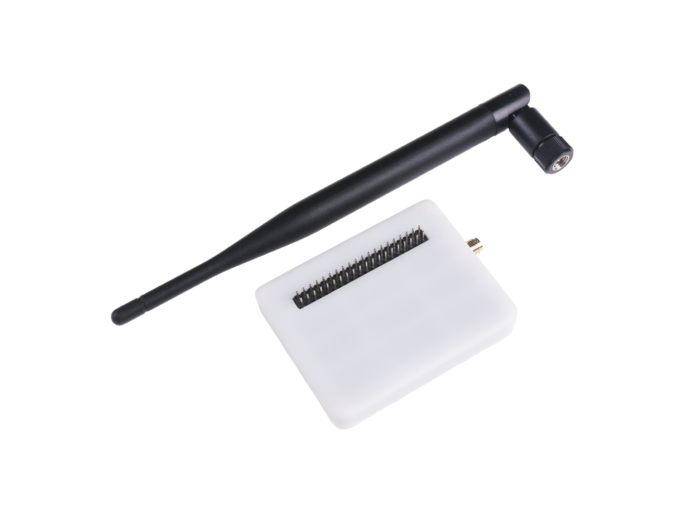
Wio Terminal LoRaWan Chassis with Antenna-built-in LoRa-E5 and GNSS, EU868/US915

Wio Terminal LoRaWan Chassis with Antenna-built-in LoRa-E5 and GNSS, EU868/US915 embedded with LoRa-E5 STM32WLE5JC, powered by ARM Cortex M4 ultra-low-power MCU core and LoRa SX126x, is a wireless radio module supporting LoRa and LoRaWAN protocol on the EU868 & US915 frequency and (G)FSK, BPSK, (G)MSK, LoRa modulations. Wio Terminal LoRaWan Chassis with Antenna-built-in LoRa-E5 and GNSS, EU868/US915 can endow your development boards' strong features of ultra-long transmitting range by easily plug and play with Grove connector on board.
As an upgrade of our old version - Grove - LoRa Radio - powered by RFM95 ultra-long-range Transceiver Module, Grove LoRa-E5 embedded with LoRa-E5 STM32WLE5JC Module is a high-performance and easy-to-use wireless radio LoRa module supporting LoRaWAN protocol.
LoRa-E5 LoRaWAN STM32WLE5JC module is the major functional part integrated into Wio Terminal LoRaWan Chassis with Antenna-built-in LoRa-E5 and GNSS, EU868/US915. It is a LoRaWAN module that embedded with ARM Cortex M4 ultra-low-power MCU core and LoRa SX126x, as the world-first combo of LoRa RF and MCU chip into one single tiny module, it supports (G)FSK, BPSK, (G)MSK, and LoRa modulations, and is FCC, CE certified. (Learn more about LoRa-E5 from LoRa-E5 wiki)
More comparison between the LoRa-E5 and RFM95 chip:

By connecting Wio Terminal LoRaWan Chassis with Antenna-built-in LoRa-E5 and GNSS, EU868/US915 to your development boards, your devices are able to communicate with and control LoRa-E5 conveniently by AT command through UART connection. Grove LoRa-E5 will be a superior choice for IoT device development, testing, and long-distance, ultra-low power consumption IoT scenarios like smart agriculture, smart office, and smart industry. It is designed with industrial standards with a wide working temperature at -40℃ ~ 85℃, high sensitivity between -136 dBm and -137 dBm, and power output between 10 dBm and 22 dBm.
Features
- LoRa-E5 (STM32WLE5JC) embedded
- Support LoRaWAN protocol on EU868/US915 frequency band
- Ultra-long transmitting range up to 10km (Ideal value in open space)
- Easy control by AT command via UART connection
- Rapid prototyping with plug-and-play Grove interfaces
- Ultra-low power consumption and high performance
Harware Overview

- LoRa-E5 STM32WLE5JC (Datasheet)
- MHF IPEX Connector
- Wire Antenna
- Grove Connector
- LED Indicators
Platform Supported
| Arduino | Raspberry Pi | |||
|---|---|---|---|---|
Specification
| General Parameters | |
|---|---|
| Voltage Supply: | 3.3V/5V |
| Power Output: | Up to +20 dBm at 3.3V |
| Working Frequency | 868/915MHz |
| Protocol | LoRaWAN |
| Sensitivity | -116.5dBm ~ -136dBm |
| Modulation | LoRa, (G)FSK, (G)MSK and BPSK |
| Current | Only 60uA in sleep mode |
| Size | 20*40mm |
| Working Temperature | -40℃ ~ 85℃ |
Part List
| Products | Quantity |
|---|---|
| Wio Terminal LoRaWan Chassis with Antenna-built-in LoRa-E5 and GNSS, EU868/US915 | *1 |
| Antenna | *1 |
Application
- LoRaWAN GPS Tracker
- LoRaWAN Field Tester
- Smart Agriculture
- Smart Cities
- Smart Factory
- Rapid prototyping of LoRa devices with Wio Terminal
- Any long-distance wireless communication application development
- LoRa and LoRaWAN application learn and research
Getting Start
Materials required
| Wio Terminal | LoRaWan Chassis | Battery Chassis |
|---|---|---|
 |  |  |
| Get ONE Now | Get ONE Now | Get ONE Now |
Project 1: WioTerminal LoRaWAN Gateway Tester
Introduction
The LoRaWAN Gateway Tester is a multipurpose portable tool that can detect the coverage of your LoRaWAN gateways. It will then apprise you of whether the signal is in a normal range. Designed to make the deployment of a LoRaWAN network easier, the LoRaWAN Gateway Tester will help you determine the optimum location for your LoRaWAN gateway deployment.
Prior to developing this, we checked out the LoRa tester market; the price usually ranges from $200 to $500, however, some of them lack a backend application to report the network signal, current time, status, and several other critical information. Therefore, we decided to bring a low-cost version ourselves that is able to do more! This project is based on Paul Pinault’s WioLoRaWANFieldTester report. We are honoured to have access to his link and we thank him for his contributions. We combined Paul Pinault’s natty UI for the Wio terminal with LoRa-E5 and GNSS modules to produce the function of the LoRaWAN Gateway Tester.

Feature
- Menu selection for different modes of operation; Power controls, SF, test numbers input, etc.
- Supports various network segments (EU868, US915, US915HYBRID, AS923, KR920, IN865)
- Display LoRa device connection and uplink-downlink status
- Backup of previous test results
- Graphical display of RSSI and SNR
- Shows the number of uplink and downlink times, as well as the likelihood of packet loss
- GPS position reporting, as well as the current time and number of satellites.
- Display LoRa Device information i.e. DevEui, APPEui, Appkey, Firmware version, and more
- Define the DevEui, APPEui and Appkey
Hardware
The hardware used in this project is more affordable than most on the market, with the total cost adding up to less than a hundred dollars.
Usage
Wio Terminal instruction
The LoRaWAN Gateway Tester basically sends a frame on-demand to the gateway on a regular basis, then transfers to the server (Uplink). It then waits for an ACK status. If the LoRa tester does not receive a response, it will continue to send the same frame until the preset number has been reached. The ACK, on the other hand, returns the response(Downlink) to the LoRa tester, implying that the message is forwarded to a backend service, from whence the information is eventually shown on the Wio terminal screen. This project is based on the Arduino platform which means we’ll be using the Arduino IDE and various Arduino libraries. If this is your first time using the Wio terminal, here is a guide to quickly Get Started with Wio Terminal.
requite library:
Note
When you upload the code, please selecte slave mode.

TheThingsNetwork Console Configuration Setup
In this project, I test the LoRa tester on TheThingsNetwork platform, the instuction as below:
Step 1: Load into TTN website and create your account, then go to gateways start to set up your device.

Step 2: Add the gateway device:
- Owner
- Gteway ID
- Gateway EUI
- Gateway name


Step 3: Add Application:
- Owner
- Application ID
- Application name


Step 4:Add the LoRa node:
- Brand (Select Sense CAP)
- Model (Select LoRa-E5)
- Hardware Ver (Defult)
- Firmware Ver (Defult)
- Profile (The Region is according to your location)
- Frequency plan
- AppEUI
- DEVEUI
- AppKey
- End Device ID


Step 5: Add the code for decode the data:
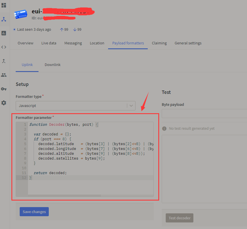
function Decoder(bytes, port) {

  var decoded = {};
  if (port === 8) {
    decoded.latitude   = (bytes[3] | (bytes[2]<<8) | (bytes[1]<<16)  | (bytes[0]<<24)) /1000000;
    decoded.longitude  = (bytes[7] | (bytes[6]<<8) | (bytes[5]<<16)  | (bytes[4]<<24)) /1000000;
    decoded.altitude   = (bytes[9] | (bytes[8]<<8));
    decoded.satellites = bytes[9];
  }

  return decoded;
}
Step 5: Cheack the result on TheThingsNetwork
Go to the geteway, then click "Live data".

Wio terminal intruction
Each LoRa device has a unique serial number, after you connect the LoRa device to the Wio terminal then there will display the deveui, appeui and appkey on the first page, you need to fill the LoRa ID and gateway ID in server.

There are Rssi and Snr data, and it will display the signal and Snr bar and packet loss after get the ACK respond.


This device have a GPS function as well, but it is not recommended for using in enclosed speace in case effect collect satellites.

schematic
Take a look at board directory for details on PCB & components. Here is the simplified version of the schematics for DiY implementation. if you want more detail, just go to check the file list.

Enclosure
The 3D printed enclosure can be found in file list which is PCBA WioTerminal Chassis H and PCB file. You will find the the all design on it. You will also find the FreeCad source file in case you want to modify /improve it.
The 3D prited work as below:


Project 2: LoRa Node with WioTerminal-IoT Smart Garden Monitor
Introduction
The IoT Smart Garden Monitor is used the Wio Terminal Chassis-LoRa-E5 and GNSS as an IoT device, it is basically sending a frame to the gateway and then transfer to the server(Uplink), in this case, I can bunch other data with the frame to upload, such as GPS, temperature and humidity, you also can bring other sensor data as you want. After the ACK obtain the response(Downlink) back to the LoRa device, the connection status will shift to conneted and display on the Wio terminal, which means the message is passed to the backend service and then you can view the data on TheThingsNetwork platform, you also can use other platforms, but the premise is that platform can support the Wio Terminal Chassis-LoRa-E5 and GNSS.

Feature
- The LoRa device can display the DevEui, APPEui and Appkey on the first page.
- it can display the current temperature, humidity and current time.
- Display longitude, latitude and satellites number.
- Display the device and TTN connection status.
Hardware
This demo you will need the device list as below:
Usage
This project is based on the Arduino platform which means we’ll be using the Arduino IDE and various Arduino libraries. If this is your first time using the Wio terminal, here is a guide to quickly Get Started with Wio Terminal.
requite library:
TheThingsNetwork Console Configuration Setup
In this project, I test the LoRa tester on TheThingsNetwork platform, the instuction as below:
Step 1: Load into TTN website and create your account, then go to gateways start to set up your device.
Step 2: Add the gateway device:
- Owner
- Gteway ID
- Gateway EUI
- Gateway name
Step 3: Add Application:
- Owner
- Application ID
- Application name
Step 4:Add the LoRa node:
- Brand (Select Sense CAP)
- Model (Select LoRa-E5)
- Hardware Ver (Defult)
- Firmware Ver (Defult)
- Profile (The Region is according to your location)
- Frequency plan
- AppEUI
- DEVEUI
- AppKey
- End Device ID
Step 5: Add the code for decode the data:
function Decoder(bytes, port) {

  var decoded = {};
  if (port === 8) {
    decoded.temp = bytes[0] <<8 | bytes[1];
    decoded.humi = bytes[2] <<8 | bytes[3];
    decoded.latitude   = (bytes[7] | (bytes[6]<<8) | (bytes[5]<<16)  | (bytes[4]<<24)) /1000000;
    decoded.longitude  = (bytes[11] | (bytes[10]<<8) | (bytes[9]<<16)  | (bytes[8]<<24)) /1000000;
    decoded.altitude   = (bytes[15] | (bytes[14]<<8) | (bytes[13]<<16) | (bytes[12]<<24))/100;
    decoded.satellites = bytes[16];
  }

  return decoded;
}
Step 5: Cheack the result on TheThingsNetwork
Go to the geteway, then click "Live data".

Note
When you upload the code, please selecte slave mode.
Each LoRa device has a unique serial number, after you connect the LoRa device to the Wio terminal then there will display the deveui, appeui and appkey on the first page, you need to fill the LoRa ID and gateway ID in server.

On the second page, there will display temperature, humidity, current time, longitude, latitude and satellites number.

PlatformIO
We also provide PlatformIO code.
IcingTomato/LoRaNode-with-WioTerminal-IoT-Smart-Garden-Monitor
IcingTomato/WioTerminal-LoRaWAN-Gateway-Tester
Resources
Datasheet:
- Wio Terminal Chassis - LoRa-E5 and GNSS v1.2.zip
- LoRa-E5 datasheet and specifications
- LoRa-E5 AT Command Specification
Certifications:
- LoRa-E5-HF Certification CE-VOC-RED
- LoRa-E5-HF FCC Certification -DSS
- LoRa-E5-HF FCC Certification -DTS
Relevant SDK:
Tech Support & Product Discussion
Thank you for choosing our products! We are here to provide you with different support to ensure that your experience with our products is as smooth as possible. We offer several communication channels to cater to different preferences and needs.