Seeed Studio XIAO RP2040 with Arduino
This is the page that we are going to connect the Seeed Studio XIAO RP2040 and program with Arduino. There will be several projects about Pin Multiplexing as well.
Getting Started
First, we are going to connect the Seeed Studio XIAO RP2040 to the computer and upload a simple code from Arduino to check whether the board is functioning well.
Hardware Setup
Materials required:
- Seeed Studio XIAO RP2040 x1
- The PC x1
- USB Type-C cable x1
Some USB cables can only supply power and cannot transfer data. If you don't have a usb cable or don't know if your usb cable can transmit data, you can check seeed USB type C support USB 3.1.
Hardware Connection:
- Step 1. Press and hold the BOOT button and then connect the Seeed Studio XIAO RP2040 to the PC.
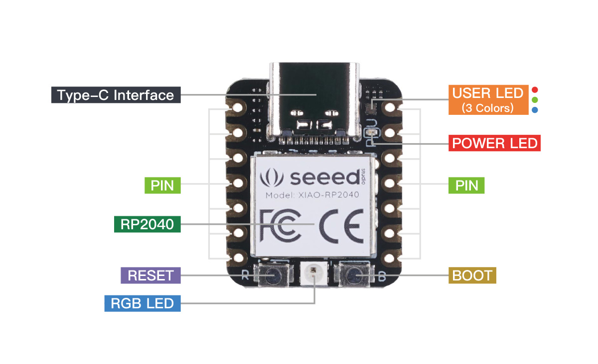
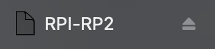
- Step 2. If the "RPI-RP2" disk is shown on the PC and the Power LED on the Seeed Studio XIAO RP2040 is turned on, the connnection is complete.
Software Setup
- Step 1. Download and Install the latest version of Arduino IDE according to your operating system

-
Step 2. Launch the Arduino application.
-
Step 3. Add Seeed Studio XIAO RP2040 board package to your Arduino IDE
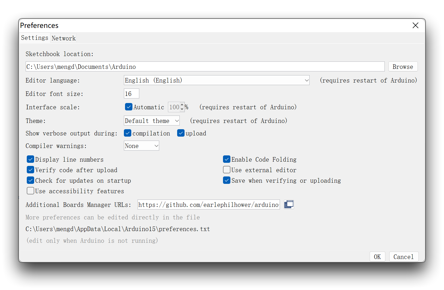
Navigate to File > Preferences, and fill Additional Boards Manager URLs with the url below:
https://github.com/earlephilhower/arduino-pico/releases/download/global/package_rp2040_index.json
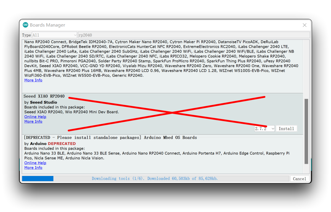
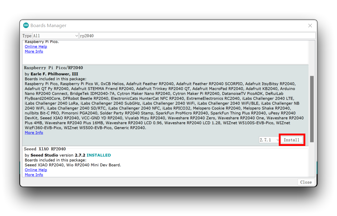
Navigate to Tools-> Board-> Boards Manager..., type the keyword "RP2040" in the searching blank. Select the lastest version of "Raspberry Pi Pico/RP2040" and install it.
The on-board package named Seeed XIAO RP2040 is no longer available, please do not download and use it!
Install the "Raspberry Pi Pico/RP2040" package, which includes the "Seeed XIAO RP2040" board.
-
Step 4. Select your board and port.
-
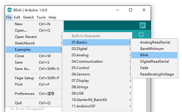
Step 5. Open the Blink example by navigating "File --> Examples --->01.Basics --> Blink"
Board
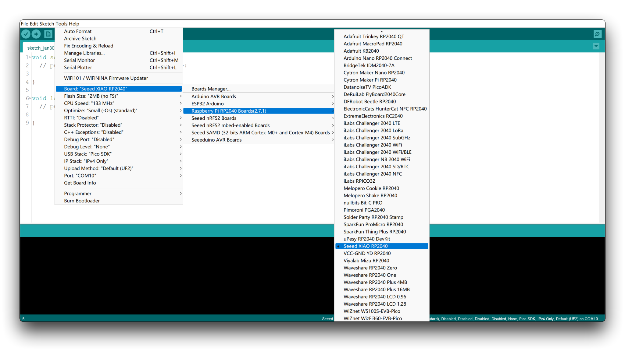
After installing the board package, navigate to Tools-> Board, find "Seeed Studio XIAO RP2040" and select it. Now we have finished setting up the Seeed Studio XIAO RP2040 for Arduino IDE.
Port
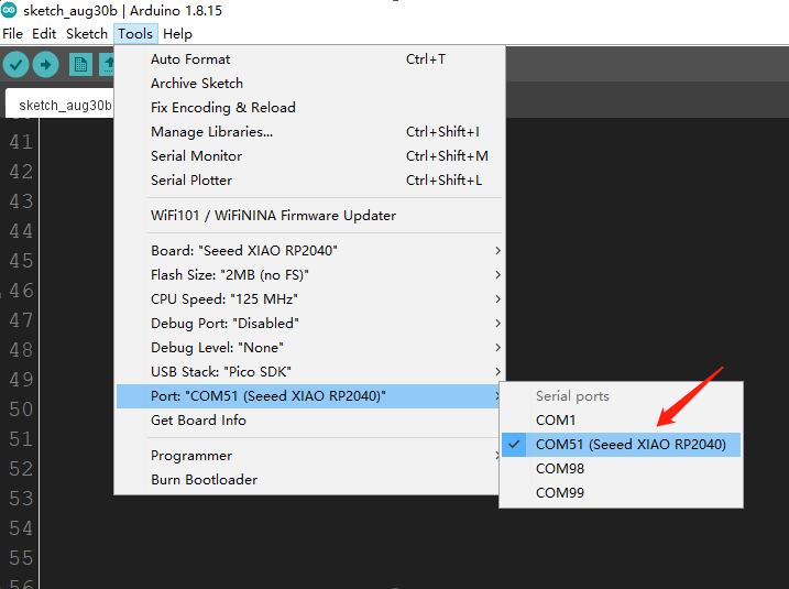
Navigate to Tools > Port and select the serial port name of the connected Seeed Studio XIAO RP2040. This is likely to be COM3 or higher (COM1 and COM2 are usually reserved for hardware serial ports). The serial port of the connected Seeed Studio XIAO RP2040 usually contains parentheses that are written "Seeed Studio XIAO RP2040".
- Step 6. Click the Upload button to upload the Blink example code to the board.
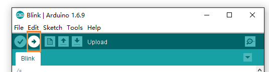
Once uploaded, you should be able to see the pin 25 Green (USER) LED on the board blinks once a second. If it does, congratulations! This means the connection is successful and now you can explore more projects with the Seeed Studio XIAO RP2040!
If uploading the Arduino program fails, try holding down the "BOOT" button and then clicking the "RUN" button. At this point, Seeed Studio XIAO RP2040 will enter boot mode (your computer will load a removable disk), and you will be able to upload the Arduino program again.
Pin Multiplexing on the Seeed Studio XIAO RP2040
The Seeed Studio XIAO RP2040 contains 11 digital pins, 4 analog pins, 11 PWM Pins,1 I2C interface, 1 UART interface, 1 SPI interface, 1 SWD Bonding pad interface. We are going to provide the tutorials about these interfaces to make it helpful for your projects.
Digital
Connect a pushbutton to Pin D0 and an LED to Pin 25. Then upload the following code to control the ON/OFF of LED using the pushbutton.
Please note that the operating voltage of the Seeed Studio XIAO RP2040 is 3.3V, if you connect the sensor to 5V incorrectly, the motherboard may not work properly.
const int buttonPin = D0;     // the number of the pushbutton pin
const int ledPin =  25;      // the number of the LED pin

int buttonState = 0;         // variable for reading the pushbutton status

void setup() {
  // initialize the LED pin as an output:
  pinMode(ledPin, OUTPUT);
  // initialize the pushbutton pin as an input:
  pinMode(buttonPin, INPUT);
}

void loop() {
  // read the state of the pushbutton value:
  buttonState = digitalRead(buttonPin);

  // check if the pushbutton is pressed. If it is, the buttonState is HIGH:
  if (buttonState == HIGH) {
    // turn LED off:
    digitalWrite(ledPin, HIGH);
  } else {
    // turn LED on:
    digitalWrite(ledPin, LOW);
  }
}
Analog
Connect a potentiometer to Pin A0 and an LED to Pin 25. Then upload the following code to control the blinking interval of the LED by rotating the potentiometer knob.
const int sensorPin = A0;
const int ledPin =  25;
void setup() {
  // declare the ledPin as an OUTPUT:
  pinMode(sensorPin, INPUT);
  pinMode(ledPin, OUTPUT);
}

void loop() {
  // read the value from the sensor:
int sensorValue = analogRead(sensorPin);
  // turn the ledPin on
  digitalWrite(ledPin, HIGH);
  // stop the program for <sensorValue> milliseconds:
  delay(sensorValue);
  // turn the ledPin off:
  digitalWrite(ledPin, LOW);
  // stop the program for for <sensorValue> milliseconds:
  delay(sensorValue);
}
Serial
Use pin D6 as the TX pin of UART and pin D7 as RX pin of UART to send the "Hello World!" message
void setup() {
    Serial.begin(115200);
    while (!Serial);
}

void loop() {
    Serial.println("Hello,World");
    delay(1000);
}
RGB LED
Pin 11 is the enable pin of RGB LED. You can light up the RGB LED by setting the Pin 11 high. Here we are going to make it go flash. First, we need to add a third-party library.
- Step 1. Open Arduino IDE, navigate to
Sketch > Include Library > Manage Libraries...to search the library.
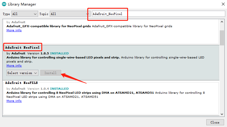
Type the keyword "Adafruit_NeoPixel" library in Ardunio library Manager and install the lastest version.
- Step 2. Copy the codes to Arduino and click the Upload button to upload.
#include <Adafruit_NeoPixel.h>

int Power = 11;
int PIN  = 12;
#define NUMPIXELS 1

Adafruit_NeoPixel pixels(NUMPIXELS, PIN, NEO_GRB + NEO_KHZ800);

void setup() {
  pixels.begin();
  pinMode(Power,OUTPUT);
  digitalWrite(Power, HIGH);

}

void loop() {
  pixels.clear();
  pixels.setPixelColor(0, pixels.Color(15, 25, 205));
  delay(400);
  pixels.show();
  pixels.clear();
  pixels.setPixelColor(0, pixels.Color(103, 25, 205));
  delay(400);
  pixels.show();
  pixels.clear();
  pixels.setPixelColor(0, pixels.Color(233, 242, 205));
  delay(400);
  pixels.show();
  pixels.clear();
  pixels.setPixelColor(0, pixels.Color(233, 23, 23));
  delay(400);
  pixels.show();
  pixels.clear();
  pixels.setPixelColor(0, pixels.Color(12, 66, 101));
  delay(400);
  pixels.show();
  delay(500);

}
The RGB LED will display rainbow color.
I2C
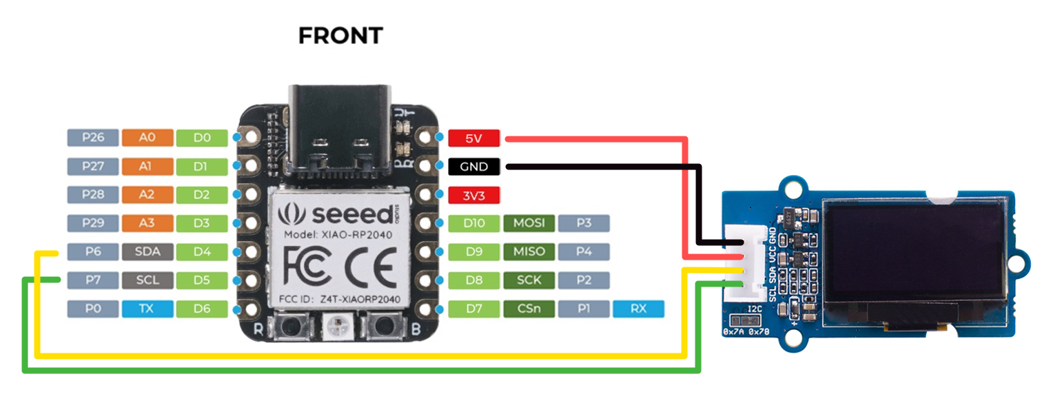
Here we are going to connect the Seeed Studio XIAO RP2040 with Grove - OLED Display 0.96" (SSD1315) through IIC and display "Hello world".
Connection:
We are going use PIN 5 as the SCL pin and PIN 4 as the SDA pin.
- Step 1. Open Arduino IDE, navigate to
Sketch > Include Library > Manage Libraries...to search the library.
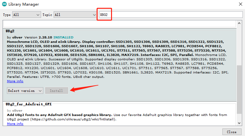
Type the keyword "U8G2" library in Ardunio library Manager and install the lastest version.
- Step 2. Copy the codes to Arduino and click the Upload button to upload.
#include <Arduino.h>
#include <U8g2lib.h>

#ifdef U8X8_HAVE_HW_SPI
#include <SPI.h>
#endif
#ifdef U8X8_HAVE_HW_I2C
#include <Wire.h>
#endif

U8G2_SSD1306_128X64_NONAME_F_SW_I2C u8g2(U8G2_R0, /* clock=*/ SCL, /* data=*/ SDA, /* reset=*/ U8X8_PIN_NONE);

void setup(void) {
  u8g2.begin();
}

void loop(void) {
  u8g2.clearBuffer();                   // clear the internal memory
  u8g2.setFont(u8g2_font_ncenB08_tr);   // choose a suitable font
  u8g2.drawStr(0,10,"Hello Wrold!");    // write something to the internal memory
  u8g2.drawStr(0,30,"Hello Werold!");
  u8g2.drawStr(0,50,"Hello Wrrrold!");
  u8g2.sendBuffer();                    // transfer internal memory to the display
  delay(1000);
}
Results are shown as:

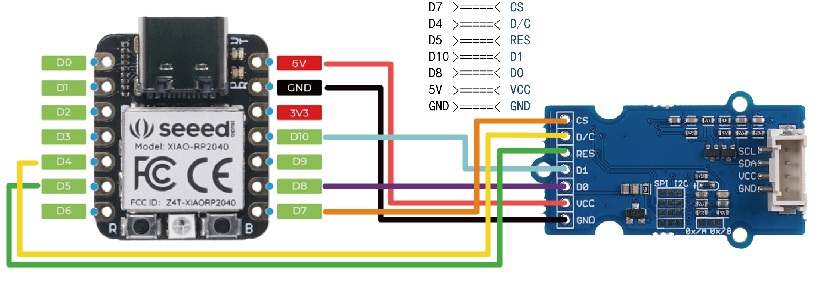
SPI
Here we are going to connect Grove - OLED Yellow&Blue Display 0.96 (SSD1315) through SPI and display "Hello World". The OLED display supports both IIC and SPI communication and yet the default communication mode is IIC. It is essential to change the IIC function to the SPI function before strarting.
Connection:
We are going use PIN 8 as the SCK pin, PIN 9 as the MISO pin and PIN10 as the MOSI pin.
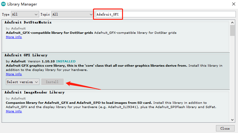
- Step 1. Open Arduino IDE, navigate to
Sketch > Include Library > Manage Libraries...to search the library.
Type the keyword "Adafruit_GFX" library in Ardunio library Manager and install the lastest version.
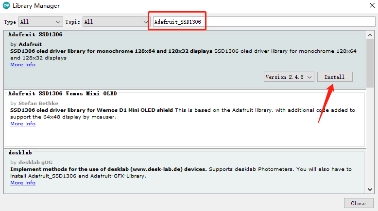
Type the keyword "Adafruit_SSD1306" library in Ardunio library Manager and install the lastest version.
- Step 2. Copy the codes to Arduino and click the Upload button to upload.
#include <SPI.h>
#include <Wire.h>
#include <Adafruit_GFX.h>
#include <Adafruit_SSD1306.h>

#define SCREEN_WIDTH 128 // OLED display width, in pixels
#define SCREEN_HEIGHT 64 // OLED display height, in pixels

// Declaration for SSD1306 display connected using software SPI (default case):
#define OLED_MOSI  MOSI   //Connect SSD1315 D1
#define OLED_CLK  SCK     //Connect SSD1315 D0
#define OLED_DC  D4      //Connect SSD1315 D/C
#define OLED_CS  SS      //Connect SSD1315 CS
#define OLED_RESET  D5   //Connect SSD1315 RES
Adafruit_SSD1306 display(SCREEN_WIDTH, SCREEN_HEIGHT,
  OLED_MOSI, OLED_CLK, OLED_DC, OLED_RESET, OLED_CS);

void setup() {
  Serial.begin(9600);
  if(!display.begin(SSD1306_SWITCHCAPVCC)) {
    Serial.println(F("SSD1306 allocation failed"));
    for(;;); // Don't proceed, loop forever
  }
}

void loop() {
  display.clearDisplay();
  display.setTextSize(1);             // Normal 1:1 pixel scale
  display.setTextColor(SSD1306_WHITE);        // Draw white text
  display.setCursor(0,3);             // Start at top-left corner
  display.println(F("Hello"));
  display.setTextSize(2);
  display.setCursor(0,16);
  display.println(F("Hello"));
  display.setTextSize(3);
  display.setCursor(0,38);
  display.println(F("Hello"));
  display.display();
  delay(2000);
}
Results are shown as below:

Tech Support & Product Discussion
Thank you for choosing our products! We are here to provide you with different support to ensure that your experience with our products is as smooth as possible. We offer several communication channels to cater to different preferences and needs.