Getting Started with Seeed Studio XIAO RP2040 Series
| Seeed Studio XIAO RP2040 | Seeed Studio XIAO RP2040 Plus |
|---|---|
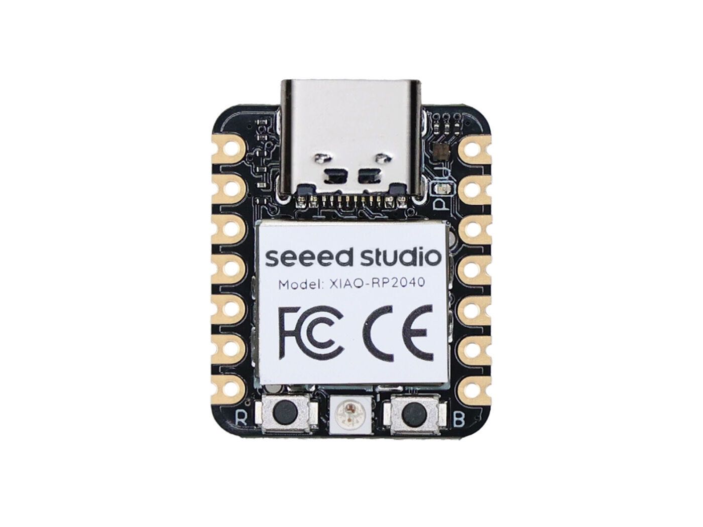 | 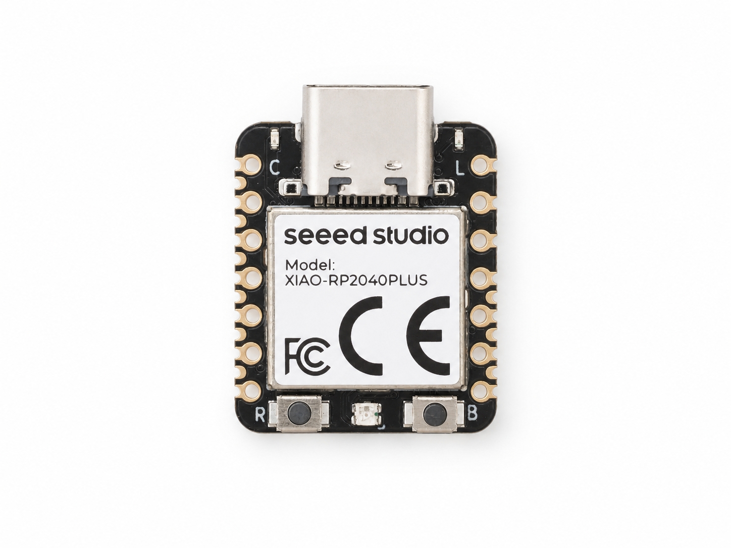 |
Overview
The Seeed Studio XIAO RP2040 series includes the XIAO RP2040 and the XIAO RP2040 Plus. Both boards are powered by the same Raspberry Pi RP2040 microcontroller, which features a dual-core Arm Cortex-M0+ processor running at up to 133 MHz and 264 KB of SRAM. Each board also includes 2 MB of onboard Flash memory. As a result, they deliver the same core processing performance and share the same RP2040 software ecosystem.
The main differences between the two boards are the number of exposed GPIOs, the available peripheral connections, and the onboard power-management features.
The standard XIAO RP2040 uses the common 14-pin XIAO footprint, consisting of 11 GPIO pins and three power pins. Its 11 digital I/O pins are PWM-capable, with four also supporting analog input. The board provides I2C, UART, SPI, and SWD interfaces in a compact 21 × 17.8 mm form factor.
The XIAO RP2040 Plus retains the same common 14-pin XIAO layout and adds 15 GPIO solder pads on the back and sides of the board. This increases the total number of exposed digital I/O pins from 11 to 26. It also adds a second I2C interface, dedicated USB D+/D− pads, and battery-related connections including BAT+, BAT−, and BAT_EN.
For battery-powered applications, the XIAO RP2040 Plus integrates an onboard PMIC, a battery charging indicator, and BAT-to-3V3 backflow protection. These additional features make the Plus version better suited for custom carrier boards, SMD assembly, battery-powered devices, and projects that require more I/O resources.
Seeed Studio XIAO RP2040 is compatible to the Seeed Studio XIAO expansion board.
Features
- Powerful RP2040 MCU: Dual-core Arm Cortex-M0+ processor running at up to 133 MHz
- Rich memory resources: 264 KB of SRAM and 2 MB of onboard Flash memory
- Broad software compatibility: Supports Arduino, PlatformIO, MicroPython, CircuitPython, TinyGo, Rust, Zephyr, and more
- Common XIAO footprint: Both versions retain the standard 14-pin XIAO layout, including 11 GPIO pins and three power pins
- Compact form factor: Thumb-sized 21 × 17.8 mm design for wearable devices and space-constrained applications
- Standard XIAO RP2040 interfaces: 11 digital I/O pins, four analog input pins, 11 PWM-capable pins, I2C, UART, SPI, and SWD
- Expanded XIAO RP2040 Plus I/O: Adds 15 GPIO pads for a total of 26 digital I/O pins, along with a second I2C interface and dedicated USB D+/D− pads
- Integrated battery management: The XIAO RP2040 Plus includes an onboard PMIC, battery charging indication, dedicated battery connections, and BAT-to-3V3 backflow protection
- Flexible assembly options: Breadboard-friendly common pins combined with castellated edges and SMD-compatible pads for custom carrier boards
Specification
| Product Name | Seeed Studio XIAO RP2040 | Seeed Studio XIAO RP2040 Plus |
|---|---|---|
| Chipset | Raspberry Pi RP2040 | |
| Processor | Dual Cortex-M0+ up to 133 MHz | |
| RAM | 264 KB SRAM | |
| Flash | 2 MB Onboard Flash | |
| Interface | GPIO Pin x14 | GPIO Pin x29 |
| Onboard | User LED × 1 | User LED × 1 |
| Battery Management (PMIC) | None | Onboard PMIC |
| Power | Input Voltage (Type-C): 5V | |
| BAT-to-3V3 Backflow Protection | No | Yes |
| Software Compatibility | Arduino, PlatformIO, MicroPython, CircuitPython, TinyGo, Rust, Zephyr, and more to come | |
| Working Temperature | -40°C to 85°C | |
| Dimensions | 21 x 17.8mm | |
| Variants | Seeed Studio XIAO RP2040 3PCS Pack Seeed Studio XIAO RP2040 Pre-Soldered | Seeed Studio XIAO RP2040 Plus |
Hardware Overview
- XIAO RP2040
- XIAO RP2040 Plus
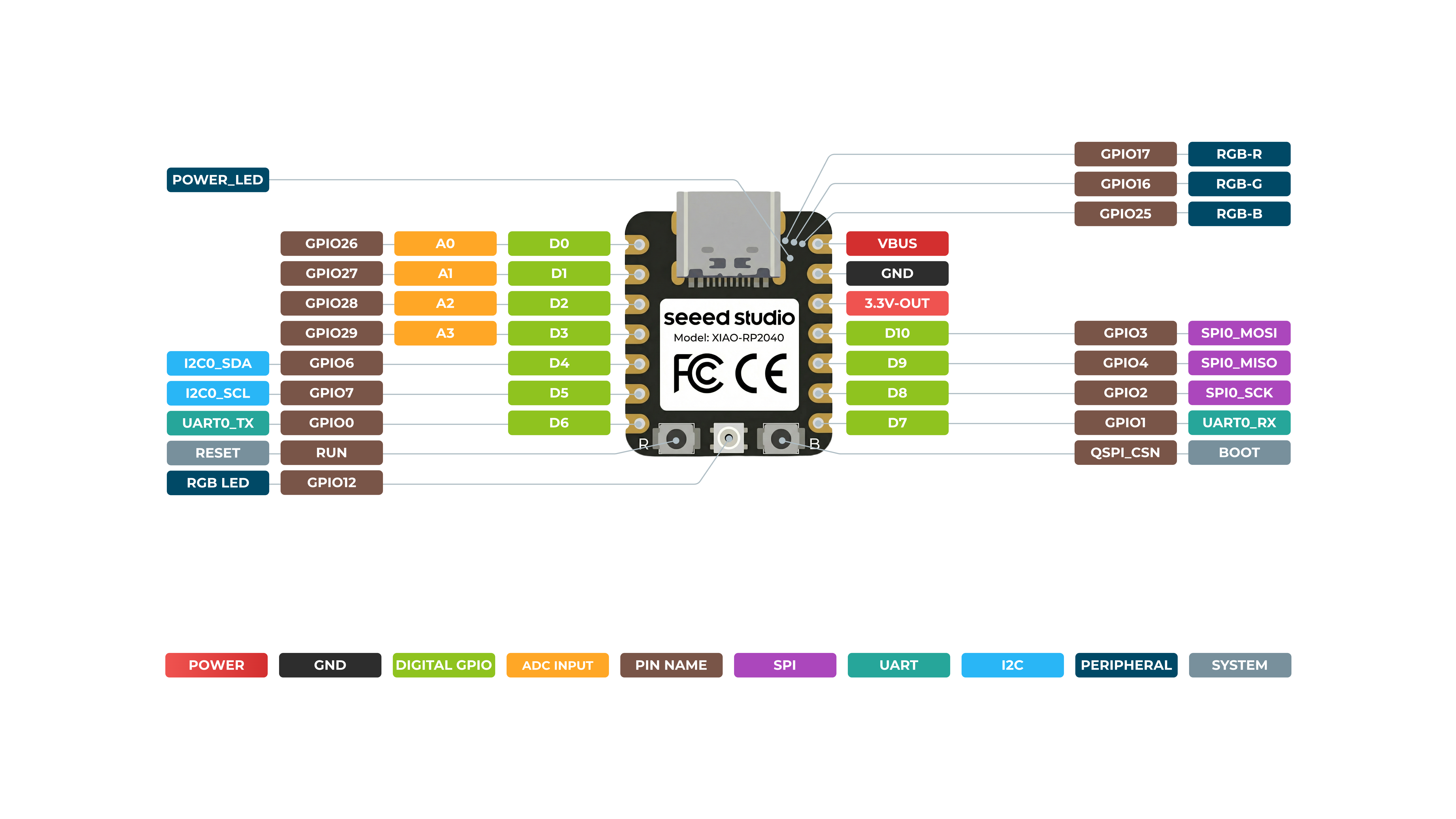
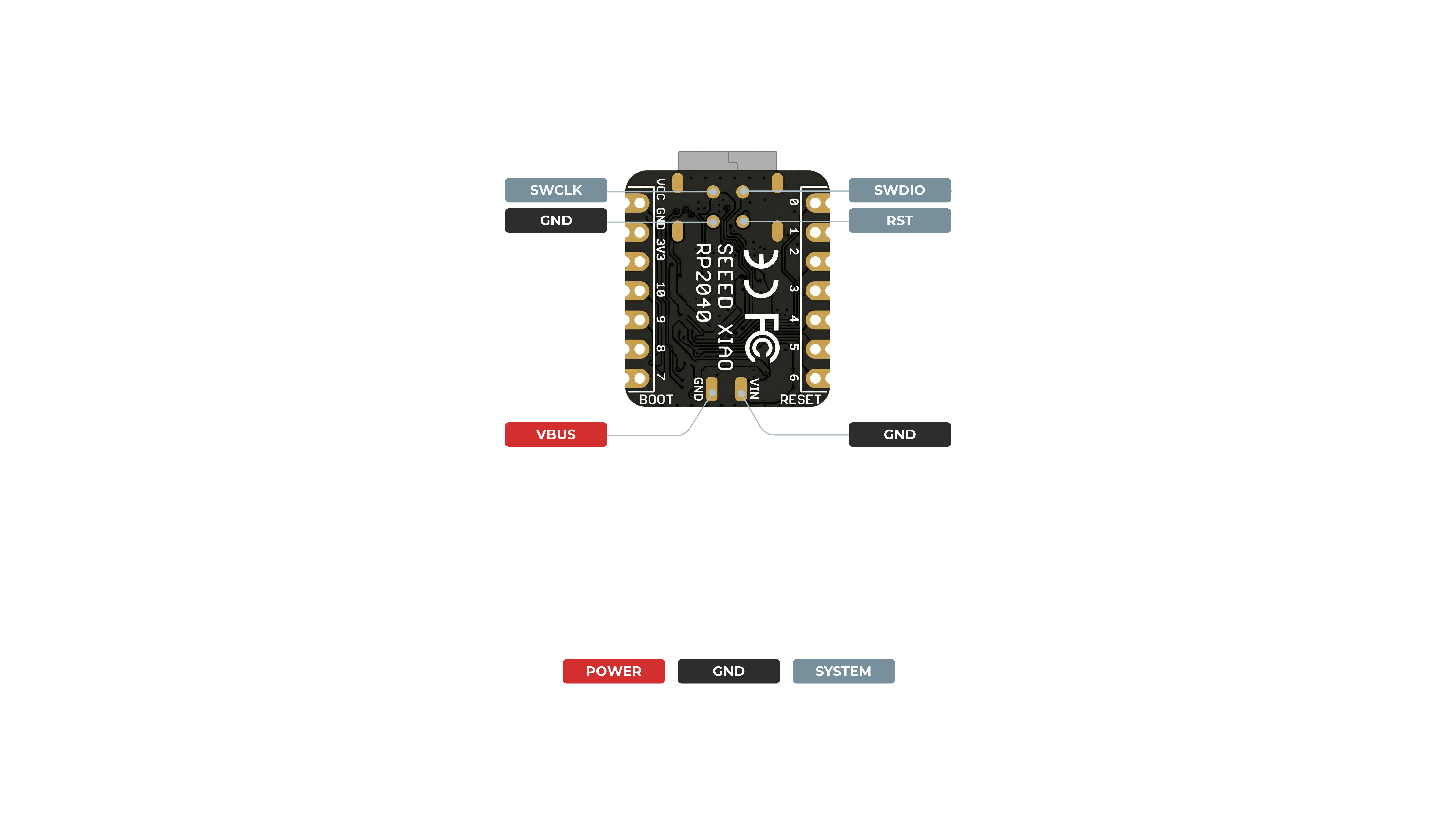
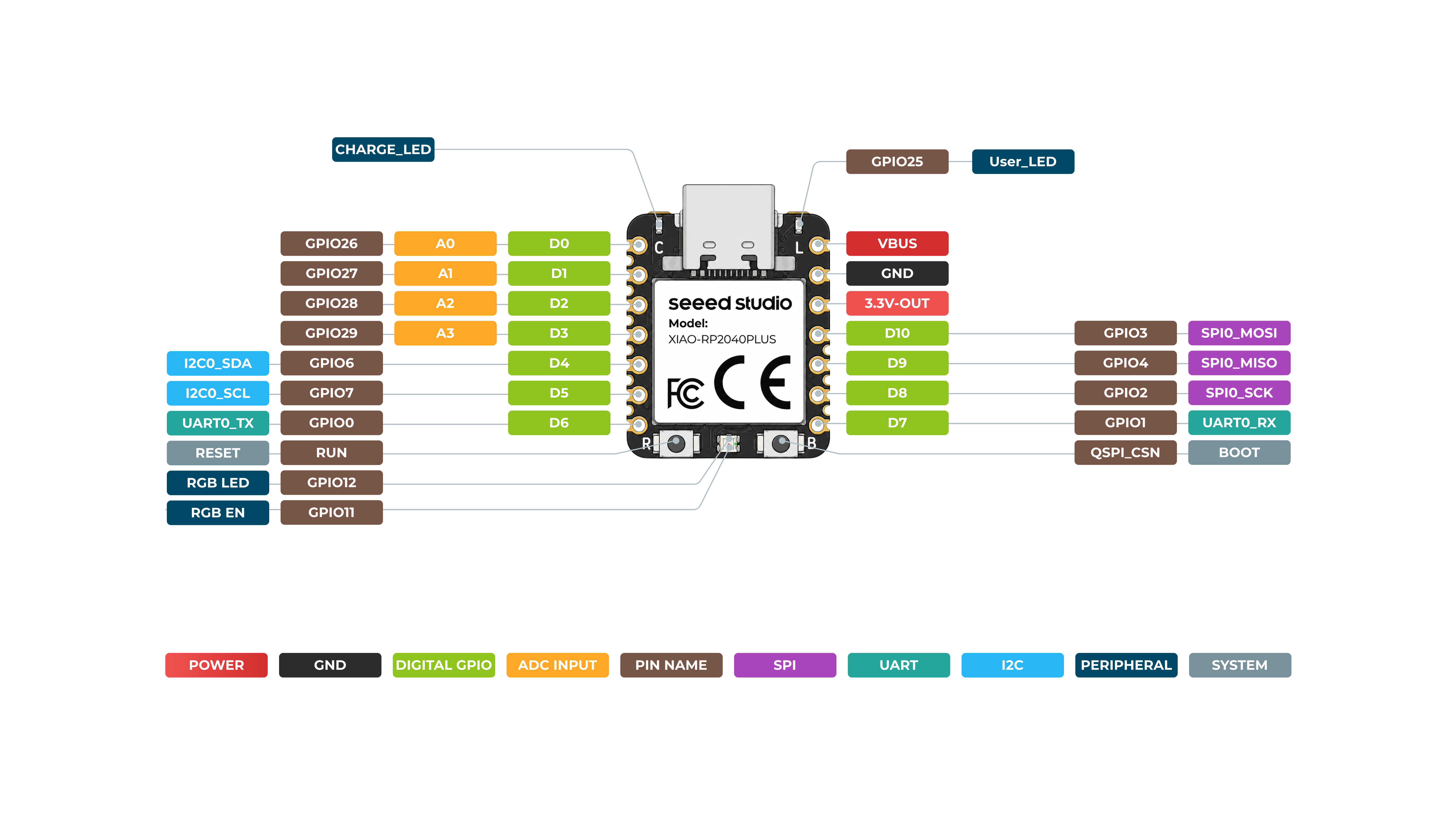
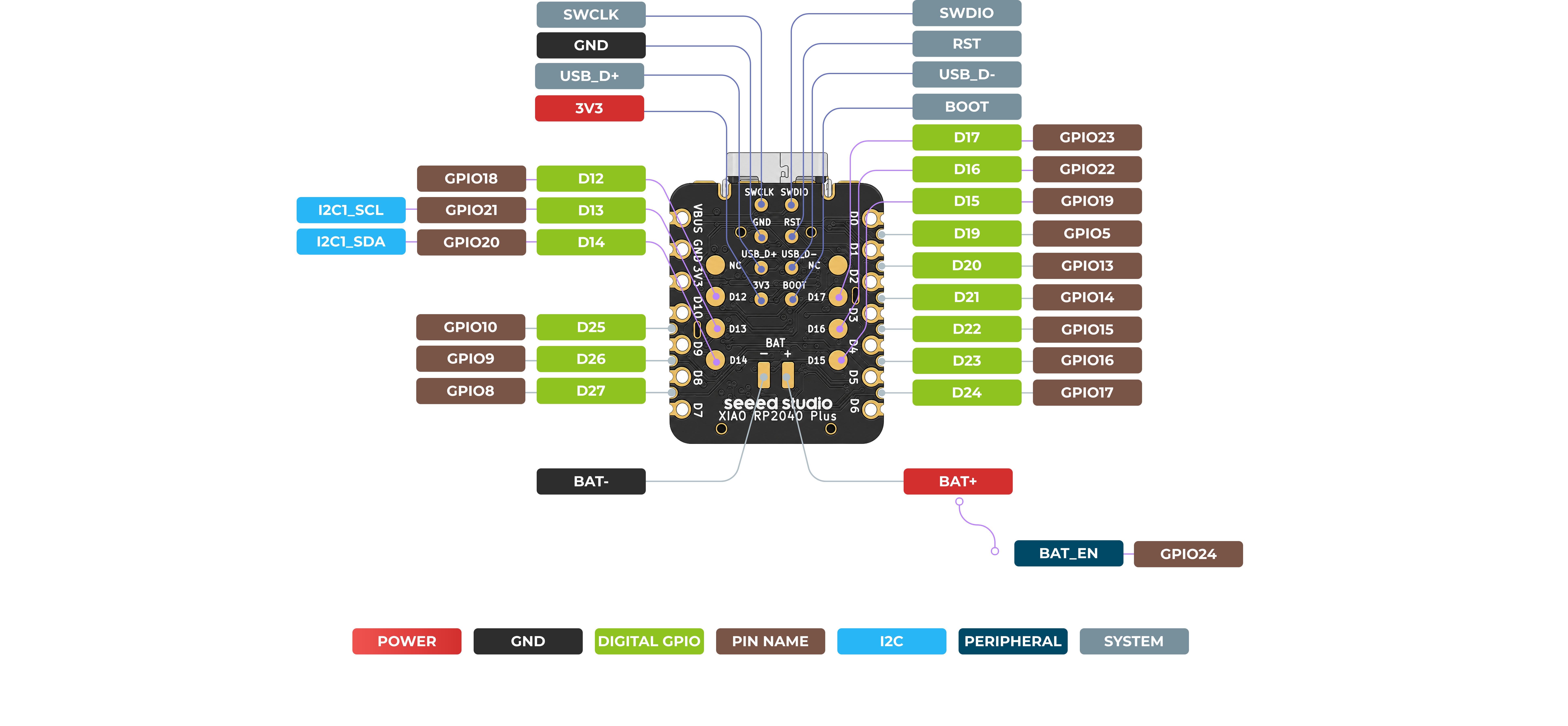
For general I/O pins: Working voltage of MCU is 3.3V. Voltage input connected to general I/O pins may cause chip damage if it's higher than 3.3V.
For power supply pins: The built-in DC-DC converter circuit able to change 5V voltage into 3.3V allows to power the device with a 5V supply via VIN-PIN and 5V-PIN.
XIAO RP2040 currently only supports battery power supply and cannot connect to Type-C while a battery is connected, as it may pose a safety risk.
Please pay attention to use, do not lift the shield cover.
Pin Map
| XIAO Pin | Function | XIAO RP2040 | XIAO RP2040 Plus | Description |
|---|---|---|---|---|
| 5V | VBUS | VBUS | VBUS | USB 5 V power input/output |
| GND | GND | GND | GND | Ground |
| 3V3 | 3V3_OUT | 3V3_OUT | 3V3_OUT | 3.3 V power output |
| D0 | A0 | GPIO26 | GPIO26 | GPIO, ADC0 |
| D1 | A1 | GPIO27 | GPIO27 | GPIO, ADC1 |
| D2 | A2 | GPIO28 | GPIO28 | GPIO, ADC2 |
| D3 | A3 | GPIO29 | GPIO29 | GPIO, ADC3 |
| D4 | SDA0 | GPIO6 | GPIO6 | GPIO, I2C0 data |
| D5 | SCL0 | GPIO7 | GPIO7 | GPIO, I2C0 clock |
| D6 | TX | GPIO0 | GPIO0 | GPIO, UART transmit |
| D7 | RX | GPIO1 | GPIO1 | GPIO, UART receive |
| D8 | SCK | GPIO2 | GPIO2 | GPIO, SPI clock |
| D9 | MISO | GPIO4 | GPIO4 | GPIO, SPI data input |
| D10 | MOSI | GPIO3 | GPIO3 | GPIO, SPI data output |
| D11 | — | — | — | Not available as an external pin |
| D12 | GPIO | — | GPIO18 | Plus-only expansion GPIO |
| D13 | SCL1 | — | GPIO21 | Plus-only I2C1 clock |
| D14 | SDA1 | — | GPIO20 | Plus-only I2C1 data |
| D15 | GPIO | — | GPIO19 | Plus-only expansion GPIO |
| D16 | GPIO | — | GPIO22 | Plus-only expansion GPIO |
| D17 | GPIO | — | GPIO23 | Plus-only expansion GPIO |
| D18 | — | — | — | Not available as an external pin |
| D19 | GPIO | — | GPIO5 | Plus-only expansion GPIO |
| D20 | GPIO | — | GPIO13 | Plus-only expansion GPIO |
| D21 | GPIO | — | GPIO14 | Plus-only expansion GPIO |
| D22 | GPIO | — | GPIO15 | Plus-only expansion GPIO |
| D23 | GPIO | — | GPIO16 | Plus-only expansion GPIO |
| D24 | GPIO | — | GPIO17 | Plus-only expansion GPIO |
| D25 | GPIO | — | GPIO10 | Plus-only expansion GPIO |
| D26 | GPIO | — | GPIO9 | Plus-only expansion GPIO |
| D27 | GPIO | — | GPIO8 | Plus-only expansion GPIO |
| Reset | RUN | RUN | RUN | Reset input |
| Boot | RP2040_BOOT | RP2040_BOOT | RP2040_BOOT | Enter bootloader mode |
| USER_LED_R | Red channel | GPIO17 | — | Direct RGB LED red-channel control on XIAO RP2040 |
| USER_LED_G | Green channel | GPIO16 | — | Direct RGB LED green-channel control on XIAO RP2040 |
| USER_LED_G | Blue channel | GPIO25 | — | Direct RGB LED blue-channel control on XIAO RP2040 |
| RGB_LED | WS2812B data | — | GPIO12/NEOPIX | Single-wire WS2812B color data control |
| RGB_EN | WS2812B enable | — | GPIO11 | Enables WS2812B power; not a color data pin |
| User LED | User-controlled LED | — | GPIO25 | Separate user LED on XIAO RP2040 Plus |
| BAT_EN | Battery Enable | — | GPIO24 | Battery power control on Plus |
| CHARGE_LED | Charging Indicator | — | — | Hardware-controlled charging status LED; not a user GPIO |
| SWDIO | SWD Debug | SWDIO | RP2040_SWDIO | Serial Wire Debug data |
| SWCLK | SWD Debug | SWCLK | RP2040_SWCLK | Serial Wire Debug clock |
| USB_D+ | USB | - | USB_DP | USB 1.1 Full-Speed data positive |
| USB_D- | USB | - | USB_DM | USB 1.1 Full-Speed data negative |
Enter Bootloader Mode
Sometimes the Seeed Studio XIAO RP2040 port may disappear when user programming process fails. We can solve this problem by the following operation:
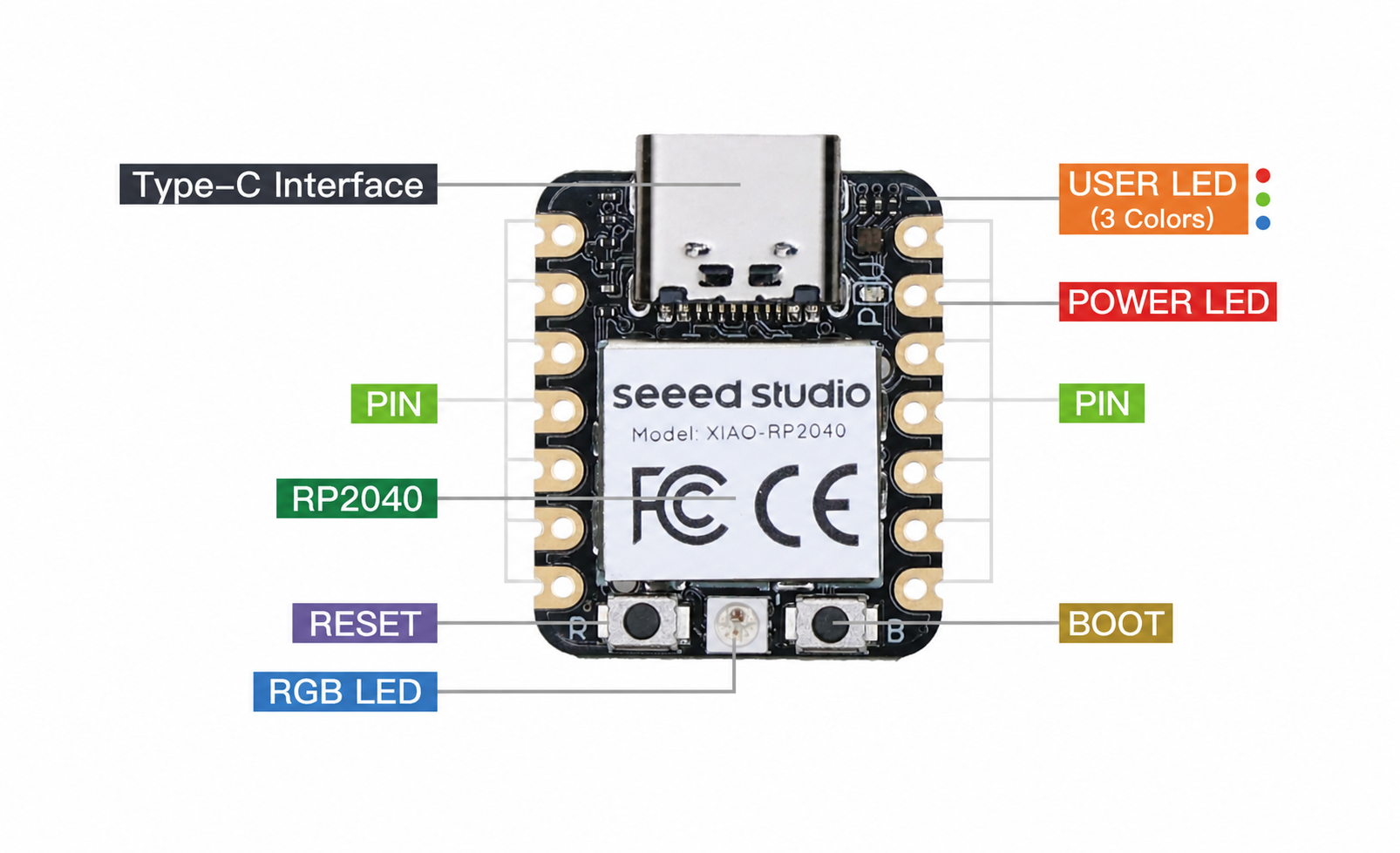
- Long press the B button.
- Connect the Seeed Studio XIAO PR2040 to your computer.
- The computer will appear a disk driver.
At this point, the chip enters Bootloader mode and the burn port appears again. Because the RP2040 chip has two partitions, one is the Bootloader and the other is the user program. The product will burn a bootloader code in the system memory when it leaves the factory. We can switch modes by performing the above steps.
Reset
If you want to reset the Seeed Studio XIAO RP2040, perform the following steps:
- Connect the Seeed Studio XIAO RP2040 to your computer.
- Press the R pins once.
Please note: The behavior of the built-in programmable Single-colour LEDs (They are red, blue and green) are reversed to the one on an Arduino. On the Seeed Studio XIAO RP2040, the pin has to be pulled low to enable.
Battery Usage
Only the XIAO RP2040 Plus features a BAT battery connector on its back side, please take note.
The XIAO RP2040 Plus is capable of using a 3.7V lithium battery as the power supply input. You can refer to the following diagram for the wiring method.

Please be careful not to short-circuit the positive and negative terminals and burn the battery and equipment when soldering. If the battery has power, never solder it onto the board, as this may burn out the circuit board. Short-circuiting while the circuit is powered on poses a significant risk; it is recommended to use an adapter.
Battery Voltage Reading Example
According to the schematic, the XIAO RP2040 Plus uses the SGM40567-4.2XG/TR lithium-ion battery charger IC to provide constant-current and constant-voltage charging for a single-cell lithium-ion battery. The charging status is indicated by the blinking Charge_LED.
The battery voltage measurement circuit uses a TPS22916CNYFPR load switch to enable or disable the measurement path. When the battery voltage needs to be measured, the MCU enables the measurement path through BAT_EN (GPIO24), thereby reducing battery consumption while the device is in standby mode.
In addition, an SGM4875XXDM6G/TR analog switch is used to switch the ADC input channel. Controlled by GPIO24/BAT_EN, it selects whether the battery measurement signal or another analog input signal is connected to the A3 (GPIO29) ADC pin, allowing the ADC pin to be multiplexed.
When the A3 pin is used as an ADC input to measure the battery voltage, it cannot be used as a general-purpose I/O pin at the same time. Make sure to take this into account when assigning pins.
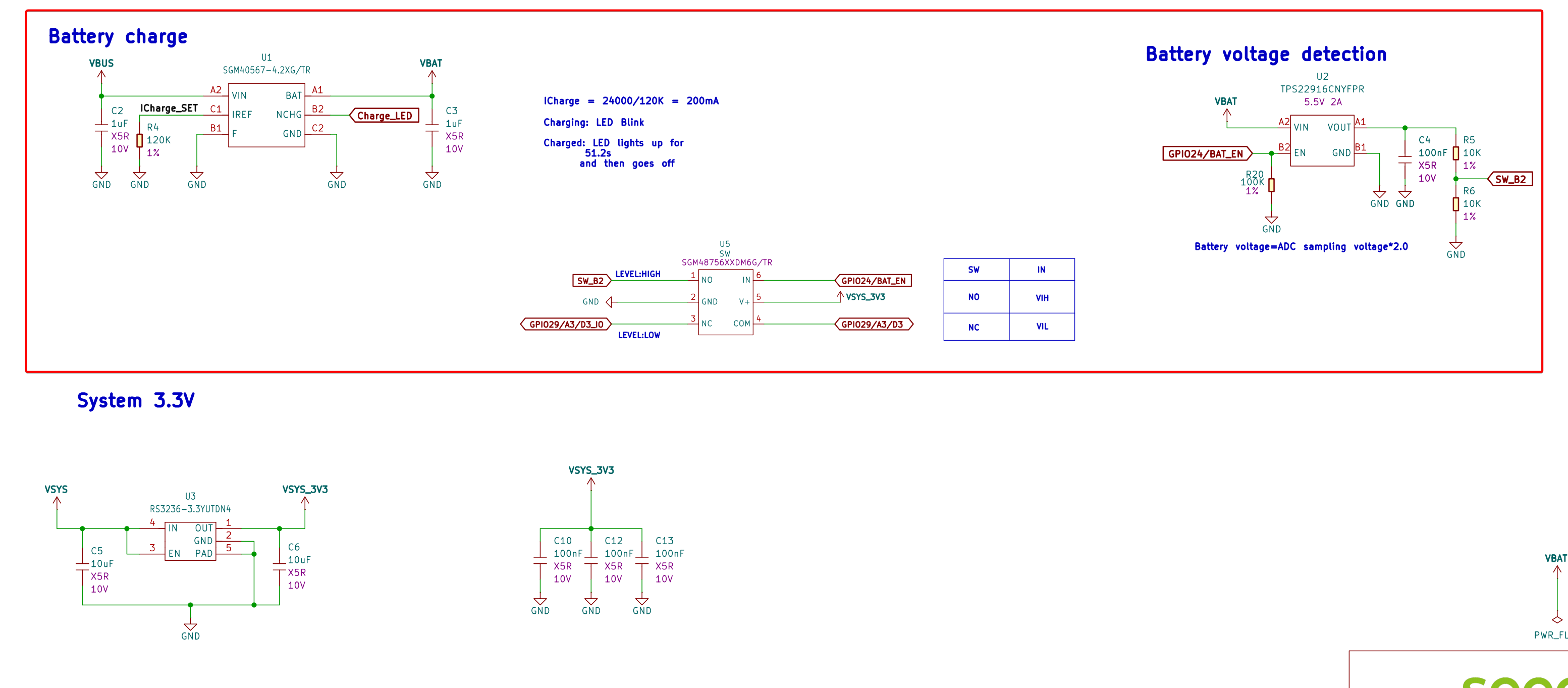
The battery voltage is measured using a resistor-divider circuit. The voltage read by the ADC is half of the actual battery voltage, so the software must multiply the ADC measurement by 2 to obtain the actual battery voltage.
Battery read example
constexpr float ADC_VREF = 3.3f;
constexpr float ADC_MAX  = 4095.0f;
constexpr float DIVIDER_RATIO = 2.0f;  // 10k / 10k voltage divider

float readBatteryVoltage() {
  // Enable voltage divider circuit and analog switch simultaneously
  digitalWrite(BAT_EN, HIGH);

  // Wait for U2 output, RC filter and ADC input to stabilize
  delay(10);

  // Discard one possibly stale ADC reading
  analogRead(A3);

  // Multiple sampling and averaging to reduce noise
  uint32_t sum = 0;
  constexpr int samples = 16;

  for (int i = 0; i < samples; i++) {
    sum += analogRead(A3);
    delay(2);
  }

  // Turn off immediately after measurement to avoid continuous power consumption by divider resistors
  digitalWrite(BAT_EN, LOW);

  float adcRaw = sum / (float)samples;
  float a3Voltage = adcRaw * ADC_VREF / ADC_MAX;

  return a3Voltage * DIVIDER_RATIO;
}

void setup() {
  Serial.begin(115200);

  pinMode(BAT_EN, OUTPUT);
  digitalWrite(BAT_EN, LOW);  // Disable detection circuit by default

  analogReadResolution(12);   // RP2040 Plus ADC: 0~4095
}

void loop() {
  float batteryVoltage = readBatteryVoltage();

  Serial.print("Battery: ");
  Serial.print(batteryVoltage, 3);
  Serial.println(" V");

  delay(1000);
}
For low-power applications, disable BAT_EN after the battery voltage measurement is complete to reduce the quiescent power consumption caused by the voltage-divider resistors.
- The Charge_LED blinks while the battery is charging.
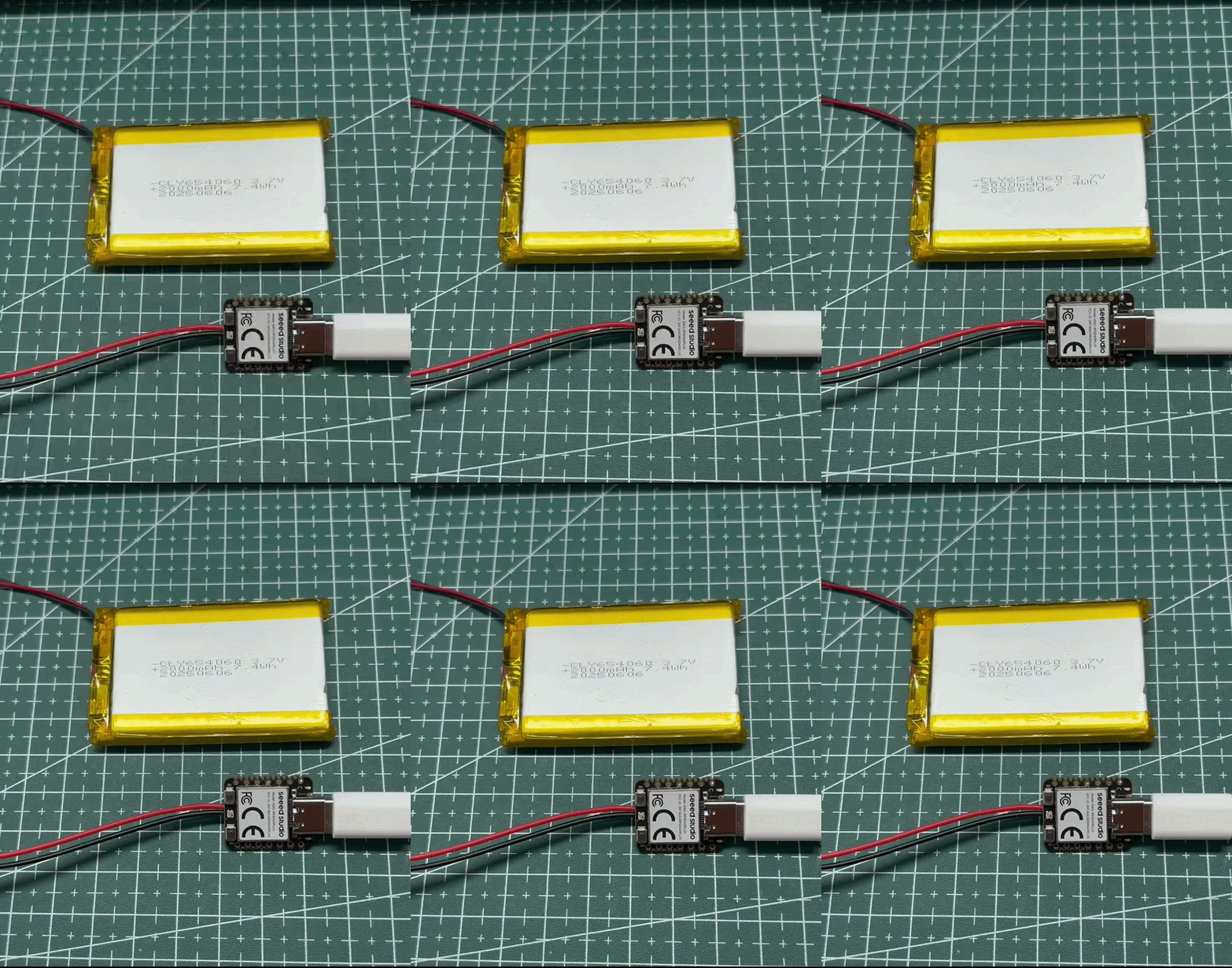
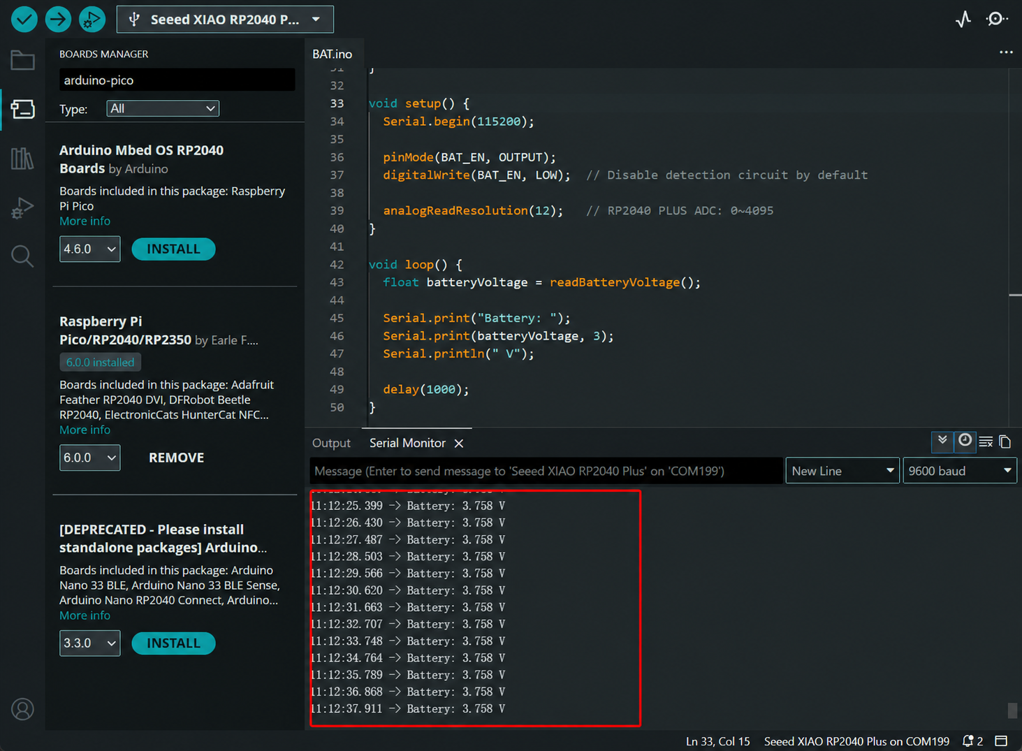
- Battery voltage measurement result: The measured voltage of a lithium-ion battery may differ from the nominal value printed on the battery. Always refer to the actual measured value.
Schematic Online Viewer
Resources
XIAO RP2040
Hardware Design
- 📄[Datasheet] Raspberry Pi RP2040 Datasheet
- 📄[Schematic] XIAO RP2040 Schematic
- 🗃️[PCB Design Files]
- 🗃️[PCB Design Libraries]
- 📄[Pinout Diagram] XIAO RP2040 Pinout Sheet
Mechanical Design
- 📄[2D Dimensions] XIAO RP2040 Dimension in DXF
- 📄[3D Model] XIAO RP2040 3D Model
XIAO RP2040 Plus
Hardware Design
- 📄[Datasheet] Raspberry Pi RP2040 Datasheet
- 📄[Schematic] XIAO RP2040 Plus Schematic
- 🗃️[PCB Design Files]
- 🗃️[PCB Design Libraries]
- 📄[Pinout Diagram] XIAO RP2040 Plus Pinout Sheet
Course Resources
Tech Support & Product Discussion
Thank you for choosing our products! We are here to provide you with different support to ensure that your experience with our products is as smooth as possible. We offer several communication channels to cater to different preferences and needs.