XIAO ESP32S3 Sense Sleep Modes
Here, I will present some simple examples to demonstrate the use of these low-power sleep modes. All ESP32 boards are versatile, and the development board I am using in this context is the XIAO ESP32S3 Sense.
Hadware Oview
| Seeed Studio XIAO ESP32S3 Sense |
|---|
 |
Deep-Sleep
Introduction
In Deep-Sleep mode, the ESP32 powers off the CPUs, most of the RAM, and all digital peripherals clocked from APB_CLK. The only components that remain powered are:
- RTC controller
- ULP coprocessor
- RTC FAST memory
- RTC SLOW memory
Wake-up Methods
-
**Timer Wake-up:**The ESP32 can wake up automatically after a specified time by setting a timer.
-
**Touchpad Interrupt Wake-up:**The device can be awakened by activity on the touchpad, suitable for applications requiring user interaction.
-
**External Wake-up:**The ESP32 can be woken up by external signals (e.g., button presses), ideal for low-power applications.
-
**ULP Coprocessor Activity Wake-up:**The ULP coprocessor can operate independently, monitoring specific conditions and waking up the main CPU to save power.
-
**GPIO Wake-up:**The device can be awakened by changes in the GPIO pin states (high or low), providing flexibility for various sensors and peripherals.
Three simple examples of XIAO ESP32 S3 Sense using DeepSleep mode are given below.
Code realization
- TimerWakeUP
- ExternalWakeUp
- TouchWakeUp
- SmoothBink_ULP
#define uS_TO_S_FACTOR 1000000ULL
#define TIME_TO_SLEEP  5

RTC_DATA_ATTR int bootCount = 0;

void print_wakeup_reason() {
  esp_sleep_wakeup_cause_t wakeup_reason;

  wakeup_reason = esp_sleep_get_wakeup_cause();

  switch (wakeup_reason) {
    case ESP_SLEEP_WAKEUP_EXT0:     Serial.println("Wakeup caused by external signal using RTC_IO"); break;
    case ESP_SLEEP_WAKEUP_EXT1:     Serial.println("Wakeup caused by external signal using RTC_CNTL"); break;
    case ESP_SLEEP_WAKEUP_TIMER:    Serial.println("Wakeup caused by timer"); break;
    case ESP_SLEEP_WAKEUP_TOUCHPAD: Serial.println("Wakeup caused by touchpad"); break;
    case ESP_SLEEP_WAKEUP_ULP:      Serial.println("Wakeup caused by ULP program"); break;
    default:                        Serial.printf("Wakeup was not caused by deep sleep: %d\n", wakeup_reason); break;
  }
}

void setup() {
  Serial.begin(115200);
  delay(1000);


  ++bootCount;
  Serial.println("Boot number: " + String(bootCount));


  print_wakeup_reason();


  esp_sleep_enable_timer_wakeup(TIME_TO_SLEEP * uS_TO_S_FACTOR);
  Serial.println("Setup ESP32 to sleep for every " + String(TIME_TO_SLEEP) + " Seconds");

  Serial.println("Going to sleep now");
  Serial.flush();
  esp_deep_sleep_start();
  Serial.println("This will never be printed");
}

void loop() {

}
Detailed Notes
#define uS_TO_S_FACTOR 1000000ULL
- Define a macro to convert microseconds to seconds. 1000000ULL is the factor used to convert microseconds to seconds.
#define TIME_TO_SLEEP 5
- Define a macro that sets the time for which the ESP32 will go to sleep, in this case, 5 seconds.
RTC_DATA_ATTR int bootCount = 0;
- Declare an integer variable
bootCountwith the attributeRTC_DATA_ATTR, which allows it to retain its value during deep sleep.
void print_wakeup_reason() {
- Define a function named
print_wakeup_reason()that will print the reason the ESP32 woke up.
esp_sleep_wakeup_cause_t wakeup_reason;
- Declare a variable
wakeup_reasonof typeesp_sleep_wakeup_cause_tto store the cause of the wakeup event.
wakeup_reason = esp_sleep_get_wakeup_cause();
- Call the function
esp_sleep_get_wakeup_cause()to retrieve the reason for the wakeup and assign it to thewakeup_reasonvariable.
  switch (wakeup_reason) {
    case ESP_SLEEP_WAKEUP_EXT0:     Serial.println("Wakeup caused by external signal using RTC_IO"); break;
    case ESP_SLEEP_WAKEUP_EXT1:     Serial.println("Wakeup caused by external signal using RTC_CNTL"); break;
    case ESP_SLEEP_WAKEUP_TIMER:    Serial.println("Wakeup caused by timer"); break;
    case ESP_SLEEP_WAKEUP_TOUCHPAD: Serial.println("Wakeup caused by touchpad"); break;
    case ESP_SLEEP_WAKEUP_ULP:      Serial.println("Wakeup caused by ULP program"); break;
    default:                        Serial.printf("Wakeup was not caused by deep sleep: %d\n", wakeup_reason); break;
}
ESP_SLEEP_WAKEUP_EXT0: This wakeup reason indicates that the ESP32 woke up due to an external signal detected on a GPIO pin configured for RTC (Real-Time Clock) I/O. This is typically used for wakeup from sleep when a button or sensor is triggered.ESP_SLEEP_WAKEUP_EXT1: This indicates that the wakeup was caused by an external signal on GPIO pins managed by the RTC controller. Unlike EXT0, EXT1 can handle multiple pins and can wake up when any of the specified pins change state (e.g., go low or high).ESP_SLEEP_WAKEUP_TIMER: This wakeup reason signifies that the ESP32 woke up after a predefined timer duration. This is useful for applications that need to perform periodic tasks without requiring user interaction.ESP_SLEEP_WAKEUP_TOUCHPAD: This indicates that the ESP32 woke up due to a touchpad event. If a touchpad configured for wakeup detects a touch, it can bring the device out of sleep mode.ESP_SLEEP_WAKEUP_ULP: This wakeup reason means that the wakeup was triggered by a ULP (Ultra-Low Power) program. ULPs can run while the main CPU is in deep sleep and can wake the ESP32 when certain conditions are met, allowing for low-power operation with minimal battery drain.
++bootCount;
- Increment the boot count and print it every time the device reboots.
print_wakeup_reason();
- Print the reason for the ESP32's wakeup.
esp_sleep_enable_timer_wakeup(TIME_TO_SLEEP * uS_TO_S_FACTOR);
Serial.println("Setup ESP32 to sleep for every " + String(TIME_TO_SLEEP) + " Seconds");

Serial.println("Going to sleep now");
Serial.flush();
esp_deep_sleep_start();
Serial.println("This will never be printed");
esp_sleep_enable_timer_wakeup(TIME_TO_SLEEP * uS_TO_S_FACTOR);Enable the timer to wake up the ESP32 after a specified time.Serial.flush();Ensure all serial data is sent before going to sleep.esp_deep_sleep_start();Put the ESP32 into deep sleep mode.
#include "driver/rtc_io.h"

#define BUTTON_PIN_BITMASK(GPIO) (1ULL << GPIO)
#define USE_EXT0_WAKEUP          1
#define WAKEUP_GPIO              GPIO_NUM_33
RTC_DATA_ATTR int bootCount = 0;


void print_wakeup_reason() {
  esp_sleep_wakeup_cause_t wakeup_reason;

  wakeup_reason = esp_sleep_get_wakeup_cause();

  switch (wakeup_reason) {
    case ESP_SLEEP_WAKEUP_EXT0:     Serial.println("Wakeup caused by external signal using RTC_IO"); break;
    case ESP_SLEEP_WAKEUP_EXT1:     Serial.println("Wakeup caused by external signal using RTC_CNTL"); break;
    case ESP_SLEEP_WAKEUP_TIMER:    Serial.println("Wakeup caused by timer"); break;
    case ESP_SLEEP_WAKEUP_TOUCHPAD: Serial.println("Wakeup caused by touchpad"); break;
    case ESP_SLEEP_WAKEUP_ULP:      Serial.println("Wakeup caused by ULP program"); break;
    default:                        Serial.printf("Wakeup was not caused by deep sleep: %d\n", wakeup_reason); break;
  }
}

void setup() {
  Serial.begin(115200);
  delay(1000);

  ++bootCount;
  Serial.println("Boot number: " + String(bootCount));

  print_wakeup_reason();

#if USE_EXT0_WAKEUP
  esp_sleep_enable_ext0_wakeup(WAKEUP_GPIO, 1);

  rtc_gpio_pullup_dis(WAKEUP_GPIO);
  rtc_gpio_pulldown_en(WAKEUP_GPIO);

#else
  esp_sleep_enable_ext1_wakeup_io(BUTTON_PIN_BITMASK(WAKEUP_GPIO), ESP_EXT1_WAKEUP_ANY_HIGH);

  rtc_gpio_pulldown_en(WAKEUP_GPIO);
  rtc_gpio_pullup_dis(WAKEUP_GPIO);
#endif

  Serial.println("Going to sleep now");
  esp_deep_sleep_start();
  Serial.println("This will never be printed");
}

void loop() {
}
Detailed Notes
#include "driver/rtc_io.h"
- Include the RTC I/O driver for accessing RTC GPIO.
#define BUTTON_PIN_BITMASK(GPIO) (1ULL << GPIO)
#define USE_EXT0_WAKEUP          1
#define WAKEUP_GPIO              GPIO_NUM_33
RTC_DATA_ATTR int bootCount = 0;
- 2 ^ GPIO_NUMBER in hex
- 1 = EXT0 wakeup, 0 = EXT1 wakeup
- Only RTC IO are allowed - ESP32 Pin example
  switch (wakeup_reason) {
    case ESP_SLEEP_WAKEUP_EXT0:     Serial.println("Wakeup caused by external signal using RTC_IO"); break;
    case ESP_SLEEP_WAKEUP_EXT1:     Serial.println("Wakeup caused by external signal using RTC_CNTL"); break;
    case ESP_SLEEP_WAKEUP_TIMER:    Serial.println("Wakeup caused by timer"); break;
    case ESP_SLEEP_WAKEUP_TOUCHPAD: Serial.println("Wakeup caused by touchpad"); break;
    case ESP_SLEEP_WAKEUP_ULP:      Serial.println("Wakeup caused by ULP program"); break;
    default:                        Serial.printf("Wakeup was not caused by deep sleep: %d\n", wakeup_reason); break;
}
ESP_SLEEP_WAKEUP_EXT0: This wakeup reason indicates that the ESP32 woke up due to an external signal detected on a GPIO pin configured for RTC (Real-Time Clock) I/O. This is typically used for wakeup from sleep when a button or sensor is triggered.ESP_SLEEP_WAKEUP_EXT1: This indicates that the wakeup was caused by an external signal on GPIO pins managed by the RTC controller. Unlike EXT0, EXT1 can handle multiple pins and can wake up when any of the specified pins change state (e.g., go low or high).ESP_SLEEP_WAKEUP_TIMER: This wakeup reason signifies that the ESP32 woke up after a predefined timer duration. This is useful for applications that need to perform periodic tasks without requiring user interaction.ESP_SLEEP_WAKEUP_TOUCHPAD: This indicates that the ESP32 woke up due to a touchpad event. If a touchpad configured for wakeup detects a touch, it can bring the device out of sleep mode.ESP_SLEEP_WAKEUP_ULP: This wakeup reason means that the wakeup was triggered by a ULP (Ultra-Low Power) program. ULPs can run while the main CPU is in deep sleep and can wake the ESP32 when certain conditions are met, allowing for low-power operation with minimal battery drain.
  Serial.begin(115200);
  delay(1000);
  ++bootCount;
  Serial.println("Boot number: " + String(bootCount));
  print_wakeup_reason();
++bootCount;Increment boot number and print it every rebootprint_wakeup_reason();Print the wakeup reason for ESP32
#if USE_EXT0_WAKEUP
  esp_sleep_enable_ext0_wakeup(WAKEUP_GPIO, 1);

  rtc_gpio_pullup_dis(WAKEUP_GPIO);
  rtc_gpio_pulldown_en(WAKEUP_GPIO);
esp_sleep_enable_ext0_wakeup(WAKEUP_GPIO, 1);Enable EXT0 wakeup on the specified GPIO pin when it goes high.rtc_gpio_pullup_dis(WAKEUP_GPIO);Disable pull-up resistor on the wakeup GPIO pin.rtc_gpio_pulldown_en(WAKEUP_GPIO);Enable pull-down resistor on the wakeup GPIO pin.
#else
  esp_sleep_enable_ext1_wakeup_io(BUTTON_PIN_BITMASK(WAKEUP_GPIO), ESP_EXT1_WAKEUP_ANY_HIGH);

  rtc_gpio_pulldown_en(WAKEUP_GPIO);
  rtc_gpio_pullup_dis(WAKEUP_GPIO);
-
esp_sleep_enable_ext1_wakeup_io(BUTTON_PIN_BITMASK(WAKEUP_GPIO), ESP_EXT1_WAKEUP_ANY_HIGH);EXT1 WAKEUP -
rtc_gpio_pulldown_en(WAKEUP_GPIO);GPIO33 is tie to GND in order to wake up in HIGH -
rtc_gpio_pullup_dis(WAKEUP_GPIO);Disable PULL_UP in order to allow it to wakeup on HIGH -
esp_sleep_enable_ext1_wakeup_io(BUTTON_PIN_BITMASK(WAKEUP_GPIO), ESP_EXT1_WAKEUP_ANY_HIGH);If you were to use ext1, you would use it like -
rtc_gpio_pulldown_en(WAKEUP_GPIO);GPIO33 is tie to GND in order to wake up in HIGH -
rtc_gpio_pullup_dis(WAKEUP_GPIO);Disable PULL_UP in order to allow it to wakeup on HIGH
  Serial.println("Going to sleep now");
  esp_deep_sleep_start();
  Serial.println("This will never be printed");
esp_deep_sleep_start();Put the ESP32 into deep sleep mode.
#if CONFIG_IDF_TARGET_ESP32
#define THRESHOLD 40
#elif (CONFIG_IDF_TARGET_ESP32S2 || CONFIG_IDF_TARGET_ESP32S3)
#define THRESHOLD 5000
#else
#define THRESHOLD 500
#endif

RTC_DATA_ATTR int bootCount = 0;
touch_pad_t touchPin;

void print_wakeup_reason() {
  esp_sleep_wakeup_cause_t wakeup_reason;

  wakeup_reason = esp_sleep_get_wakeup_cause();

  switch (wakeup_reason) {
    case ESP_SLEEP_WAKEUP_EXT0:     Serial.println("Wakeup caused by external signal using RTC_IO"); break;
    case ESP_SLEEP_WAKEUP_EXT1:     Serial.println("Wakeup caused by external signal using RTC_CNTL"); break;
    case ESP_SLEEP_WAKEUP_TIMER:    Serial.println("Wakeup caused by timer"); break;
    case ESP_SLEEP_WAKEUP_TOUCHPAD: Serial.println("Wakeup caused by touchpad"); break;
    case ESP_SLEEP_WAKEUP_ULP:      Serial.println("Wakeup caused by ULP program"); break;
    default:                        Serial.printf("Wakeup was not caused by deep sleep: %d\n", wakeup_reason); break;
  }
}

void print_wakeup_touchpad() {
  touchPin = esp_sleep_get_touchpad_wakeup_status();

#if CONFIG_IDF_TARGET_ESP32
  switch (touchPin) {
    case 0:  Serial.println("Touch detected on GPIO 4"); break;
    case 1:  Serial.println("Touch detected on GPIO 0"); break;
    case 2:  Serial.println("Touch detected on GPIO 2"); break;
    case 3:  Serial.println("Touch detected on GPIO 15"); break;
    case 4:  Serial.println("Touch detected on GPIO 13"); break;
    case 5:  Serial.println("Touch detected on GPIO 12"); break;
    case 6:  Serial.println("Touch detected on GPIO 14"); break;
    case 7:  Serial.println("Touch detected on GPIO 27"); break;
    case 8:  Serial.println("Touch detected on GPIO 33"); break;
    case 9:  Serial.println("Touch detected on GPIO 32"); break;
    default: Serial.println("Wakeup not by touchpad"); break;
  }
#else
  if (touchPin < TOUCH_PAD_MAX) {
    Serial.printf("Touch detected on GPIO %d\n", touchPin);
  } else {
    Serial.println("Wakeup not by touchpad");
  }
#endif
}

void setup() {
  Serial.begin(115200);
  delay(1000);

  ++bootCount;
  Serial.println("Boot number: " + String(bootCount));

  print_wakeup_reason();
  print_wakeup_touchpad();

#if CONFIG_IDF_TARGET_ESP32

  touchSleepWakeUpEnable(T3, THRESHOLD);
  touchSleepWakeUpEnable(T7, THRESHOLD);

#else
  touchSleepWakeUpEnable(T3, THRESHOLD);

#endif

  Serial.println("Going to sleep now");
  esp_deep_sleep_start();
  Serial.println("This will never be printed");
}

void loop() {

}
Detailed Notes
#if CONFIG_IDF_TARGET_ESP32
#define THRESHOLD 40
#elif (CONFIG_IDF_TARGET_ESP32S2 || CONFIG_IDF_TARGET_ESP32S3)
#define THRESHOLD 5000
#else
#define THRESHOLD 500
#endif
- Check if the target is ESP32
- Define the threshold for touch sensitivity for ESP32
- Check if the target is ESP32S2 or ESP32S3
- Define a higher threshold for touch sensitivity for ESP32S2/S3
- If the target is none of the above
- Define a default threshold for other targets
RTC_DATA_ATTR int bootCount = 0; // Declare a variable to count boots, stored in RTC memory.
touch_pad_t touchPin; // Declare a variable to hold the touchpad pin status.

void print_wakeup_reason() { // Function to print the reason for waking up.
  esp_sleep_wakeup_cause_t wakeup_reason; // Variable to hold the wakeup reason.

  wakeup_reason = esp_sleep_get_wakeup_cause(); // Get the cause of the wakeup.
RTC_DATA_ATTR int bootCount = 0;Declare a variable to count boots, stored in RTC memory.touch_pad_t touchPin;Declare a variable to hold the touchpad pin status.void print_wakeup_reason()Function to print the reason for waking up.esp_sleep_wakeup_cause_t wakeup_reason;Variable to hold the wakeup reason.wakeup_reason = esp_sleep_get_wakeup_cause();Get the cause of the wakeup.
  switch (wakeup_reason) {
    case ESP_SLEEP_WAKEUP_EXT0:     Serial.println("Wakeup caused by external signal using RTC_IO"); break;
    case ESP_SLEEP_WAKEUP_EXT1:     Serial.println("Wakeup caused by external signal using RTC_CNTL"); break;
    case ESP_SLEEP_WAKEUP_TIMER:    Serial.println("Wakeup caused by timer"); break;
    case ESP_SLEEP_WAKEUP_TOUCHPAD: Serial.println("Wakeup caused by touchpad"); break;
    case ESP_SLEEP_WAKEUP_ULP:      Serial.println("Wakeup caused by ULP program"); break;
    default:                        Serial.printf("Wakeup was not caused by deep sleep: %d\n", wakeup_reason); break;
}
ESP_SLEEP_WAKEUP_EXT0: This wakeup reason indicates that the ESP32 woke up due to an external signal detected on a GPIO pin configured for RTC (Real-Time Clock) I/O. This is typically used for wakeup from sleep when a button or sensor is triggered.ESP_SLEEP_WAKEUP_EXT1: This indicates that the wakeup was caused by an external signal on GPIO pins managed by the RTC controller. Unlike EXT0, EXT1 can handle multiple pins and can wake up when any of the specified pins change state (e.g., go low or high).ESP_SLEEP_WAKEUP_TIMER: This wakeup reason signifies that the ESP32 woke up after a predefined timer duration. This is useful for applications that need to perform periodic tasks without requiring user interaction.ESP_SLEEP_WAKEUP_TOUCHPAD: This indicates that the ESP32 woke up due to a touchpad event. If a touchpad configured for wakeup detects a touch, it can bring the device out of sleep mode.ESP_SLEEP_WAKEUP_ULP: This wakeup reason means that the wakeup was triggered by a ULP (Ultra-Low Power) program. ULPs can run while the main CPU is in deep sleep and can wake the ESP32 when certain conditions are met, allowing for low-power operation with minimal battery drain.
void print_wakeup_touchpad() {
  touchPin = esp_sleep_get_touchpad_wakeup_status();

#if CONFIG_IDF_TARGET_ESP32
  switch (touchPin) {
    case 0:  Serial.println("Touch detected on GPIO 4"); break;
    case 1:  Serial.println("Touch detected on GPIO 0"); break;
    case 2:  Serial.println("Touch detected on GPIO 2"); break;
    case 3:  Serial.println("Touch detected on GPIO 15"); break;
    case 4:  Serial.println("Touch detected on GPIO 13"); break;
    case 5:  Serial.println("Touch detected on GPIO 12"); break;
    case 6:  Serial.println("Touch detected on GPIO 14"); break;
    case 7:  Serial.println("Touch detected on GPIO 27"); break;
    case 8:  Serial.println("Touch detected on GPIO 33"); break;
    case 9:  Serial.println("Touch detected on GPIO 32"); break;
    default: Serial.println("Wakeup not by touchpad"); break;
  }
#else
  if (touchPin < TOUCH_PAD_MAX) {
    Serial.printf("Touch detected on GPIO %d\n", touchPin);
  } else {
    Serial.println("Wakeup not by touchpad");
  }
#endif
}
case 0:Touch detected on GPIO 4.case 1:Touch detected on GPIO 0.case 2:Touch detected on GPIO 2.case 3:Touch detected on GPIO 15.case 4:Touch detected on GPIO 13.case 5:Touch detected on GPIO 12.case 6:Touch detected on GPIO 14.case 7:Touch detected on GPIO 27.case 8:Touch detected on GPIO 33.case 9:Touch detected on GPIO 32.default:Default case if no touch detected.
void setup() {
  Serial.begin(115200);
  delay(1000);

  ++bootCount;
  Serial.println("Boot number: " + String(bootCount));

  print_wakeup_reason();
  print_wakeup_touchpad();

#if CONFIG_IDF_TARGET_ESP32

  touchSleepWakeUpEnable(T3, THRESHOLD);
  touchSleepWakeUpEnable(T7, THRESHOLD);

#else
  touchSleepWakeUpEnable(T3, THRESHOLD);

#endif

  Serial.println("Going to sleep now");
  esp_deep_sleep_start();
  Serial.println("This will never be printed");
}
-
++bootCount;Increment the boot count. -
print_wakeup_reason();Print the reason for the wakeup. -
print_wakeup_touchpad();Print the touchpad wakeup status. -
#if CONFIG_IDF_TARGET_ESP32Check if the target is ESP32 -
touchSleepWakeUpEnable(T3, THRESHOLD);Enable touch wakeup for T3 with the defined threshold. -
touchSleepWakeUpEnable(T7, THRESHOLD);Enable touch wakeup for T7 with the defined threshold. -
touchSleepWakeUpEnable(T3, THRESHOLD);Enable touch wakeup for T3 with the defined threshold. -
esp_deep_sleep_start();Put the ESP32 into deep sleep mode.
#include <Arduino.h> // Include the Arduino core library
#include "esp32/ulp.h" // Include ESP32 ULP-related library
#include "driver/rtc_io.h" // Include RTC GPIO driver library
#include "soc/rtc_io_reg.h" // Include RTC IO register definitions

#define RTC_dutyMeter 0 // Define the storage location for dutyMeter
#define RTC_dir       4 // Define the storage location for direction
#define RTC_fadeDelay 12 // Define the storage location for fadeDelay

uint32_t *fadeCycleDelay = &RTC_SLOW_MEM[RTC_fadeDelay]; // Point to the fadeDelay location in RTC_SLOW_MEM
#define ULP_START_OFFSET 32 // Define the starting offset for the ULP program

RTC_DATA_ATTR uint32_t ULP_Started = 0; // Variable to indicate if the ULP program has started
// Time-to-Sleep
#define uS_TO_S_FACTOR 1000000ULL // Conversion factor from microseconds to seconds
#define TIME_TO_SLEEP  5 // Time to enter deep sleep (in seconds)

void ulp_setup() { // ULP setup function
  if (ULP_Started) { // If ULP has already started, return
    return;
  }
  *fadeCycleDelay = 5; // Initialize fadeCycleDelay to 5
  ULP_Started = 1; // Mark ULP as started

  const gpio_num_t MeterPWMPin = GPIO_NUM_2; // Define the PWM pin
  rtc_gpio_init(MeterPWMPin); // Initialize GPIO
  rtc_gpio_set_direction(MeterPWMPin, RTC_GPIO_MODE_OUTPUT_ONLY); // Set the pin as output
  rtc_gpio_set_level(MeterPWMPin, 0); // Set the initial pin level to low

  const uint32_t MeterPWMBit = rtc_io_number_get(MeterPWMPin) + RTC_GPIO_OUT_DATA_S; // Get the bit for the PWM pin

  enum labels { // Define labels for the ULP program
    INIFINITE_LOOP,
    RUN_PWM,
    NEXT_PWM_CYCLE,
    PWM_ON,
    PWM_OFF,
    END_PWM_CYCLE,
    POSITIVE_DIR,
    DEC_DUTY,
    INC_DUTY,
  };

  // Define the ULP program
  const ulp_insn_t ulp_prog[] = {
    // Initial value setup
    I_MOVI(R0, 0), // Move 0 to register R0
    I_ST(R0, R0, RTC_dutyMeter), // Store the value of R0 in dutyMeter
    I_MOVI(R1, 1), // Move 1 to register R1
    I_ST(R1, R0, RTC_dir), // Store the value of R1 in dir

    M_LABEL(INIFINITE_LOOP), // Define the infinite loop label

    I_MOVI(R3, 0), // Move 0 to R3
    I_LD(R3, R3, RTC_fadeDelay), // Load the value from fadeDelay into R3
    M_LABEL(RUN_PWM), // Define the run PWM label

    I_MOVI(R0, 0), // Move 0 to R0
    I_LD(R0, R0, RTC_dutyMeter), // Load the value from dutyMeter into R0
    M_BL(NEXT_PWM_CYCLE, 1), // Branch to the next PWM cycle
    I_WR_REG(RTC_GPIO_OUT_W1TS_REG, MeterPWMBit, MeterPWMBit, 1), // Set the PWM pin high
    M_LABEL(PWM_ON), // Define the PWM ON label
    M_BL(NEXT_PWM_CYCLE, 1), // Branch to the next PWM cycle
    // I_DELAY(8), // Commented out delay instruction
    I_SUBI(R0, R0, 1), // Decrement R0 by 1
    M_BX(PWM_ON), // Go back to the PWM ON label

    M_LABEL(NEXT_PWM_CYCLE), // Define the next PWM cycle label
    I_MOVI(R0, 0), // Move 0 to R0
    I_LD(R0, R0, RTC_dutyMeter), // Load the value from dutyMeter into R0
    I_MOVI(R1, 100), // Move 100 to R1
    I_SUBR(R0, R1, R0), // R0 = R1 - R0
    M_BL(END_PWM_CYCLE, 1), // Branch to the end PWM cycle label
    I_WR_REG(RTC_GPIO_OUT_W1TC_REG, MeterPWMBit, MeterPWMBit, 1), // Set the PWM pin low
    M_LABEL(PWM_OFF), // Define the PWM OFF label
    M_BL(END_PWM_CYCLE, 1), // Branch to the end PWM cycle label
    // I_DELAY(8), // Commented out delay instruction
    I_SUBI(R0, R0, 1), // Decrement R0 by 1
    M_BX(PWM_OFF), // Go back to the PWM OFF label
    M_LABEL(END_PWM_CYCLE), // Define the end PWM cycle label

    I_SUBI(R3, R3, 1), // Decrement R3 by 1
    I_MOVR(R0, R3), // Move R3 to R0
    M_BGE(RUN_PWM, 1), // If R3 >= 0, branch to RUN_PWM

    I_MOVI(R1, 0), // Move 0 to R1
    I_LD(R1, R1, RTC_dutyMeter), // Load the value from dutyMeter into R1
    I_MOVI(R0, 0), // Move 0 to R0
    I_LD(R0, R0, RTC_dir), // Load the value from dir into R0

    M_BGE(POSITIVE_DIR, 1), // If R0 >= 0, branch to POSITIVE_DIR

    I_MOVR(R0, R1), // Move R1 to R0
    M_BGE(DEC_DUTY, 1), // If R1 >= 0, branch to DEC_DUTY
    I_MOVI(R3, 0), // Move 0 to R3
    I_MOVI(R2, 1), // Move 1 to R2
    I_ST(R2, R3, RTC_dir), // Store the value of R2 in dir
    M_BX(INC_DUTY), // Branch to INC_DUTY label
    M_LABEL(DEC_DUTY), // Define DEC_DUTY label
    I_SUBI(R0, R0, 2), // Decrement R0 by 2
    I_MOVI(R2, 0), // Move 0 to R2
    I_ST(R0, R2, RTC_dutyMeter), // Store the value of R0 in dutyMeter
    M_BX(INIFINITE_LOOP), // Go back to the infinite loop label

    M_LABEL(POSITIVE_DIR), // Define POSITIVE_DIR label

    I_MOVR(R0, R1), // Move R1 to R0
    M_BL(INC_DUTY, 100), // Branch to INC_DUTY label with parameter 100
    I_MOVI(R2, 0), // Move 0 to R2
    I_ST(R2, R2, RTC_dir), // Store the value of R2 in dir
    M_BX(DEC_DUTY), // Branch to DEC_DUTY label
    M_LABEL(INC_DUTY), // Define INC_DUTY label
    I_ADDI(R0, R0, 2), // Increment R0 by 2
    I_MOVI(R2, 0), // Move 0 to R2
    I_ST(R0, R2, RTC_dutyMeter), // Store the value of R0 in dutyMeter

    M_BX(INIFINITE_LOOP), // Go back to the infinite loop label
  };
  // Run the ULP program
  size_t size = sizeof(ulp_prog) / sizeof(ulp_insn_t); // Calculate the size of the ULP program
  ulp_process_macros_and_load(ULP_START_OFFSET, ulp_prog, &size); // Load the ULP program
  esp_sleep_pd_config(ESP_PD_DOMAIN_RTC_PERIPH, ESP_PD_OPTION_ON); // Configure power management for RTC peripherals
  ulp_run(ULP_START_OFFSET); // Start the ULP program
}

void setup() { // Arduino setup function
  Serial.begin(115200); // Initialize serial communication at 115200 baud rate

  ulp_setup(); // Call the ULP setup function
  Serial.printf("\nStarted smooth blink with delay %ld\n", *fadeCycleDelay); // Print startup information

  if (*fadeCycleDelay < 195) { // If fadeCycleDelay is less than 195
    *fadeCycleDelay += 10; // Increase fadeCycleDelay
  } else {
    *fadeCycleDelay = 5; // Otherwise, reset fadeCycleDelay to 5
  }
  Serial.println("Entering in Deep Sleep"); // Print entering deep sleep information
  esp_sleep_enable_timer_wakeup(TIME_TO_SLEEP * uS_TO_S_FACTOR /*/ 4*/); // Set timer wakeup
  esp_deep_sleep_start(); // Enter deep sleep
}

void loop() { // Arduino loop function
  // Empty loop
}
To re-burn the program after entering deep sleep mode, hold down the boot button and then press the reset button to reboot the ESP32.
Results Show
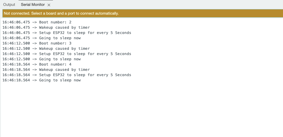
Light-Sleep
Introduction
Light Sleep mode is another low-power mode in the ESP32 that allows the device to conserve energy while still maintaining a quick response time. In this mode, the CPU cores are halted, but the RAM and some peripherals remain powered on, allowing the device to wake up quickly in response to certain events.
Light Sleep is ideal for applications that require low power consumption but still need to maintain a connection to WiFi or Bluetooth, as it allows the wireless communication modules to remain active.
Wake-up Methods
- Timer Wake-up: The device can wake up after a specified time period, allowing for periodic tasks to be executed.
- External Interrupt Wake-up: The ESP32 can be woken up by external signals, such as button presses or other hardware interrupts.
- Network Activity Wake-up: The device can wake up in response to incoming network packets, enabling efficient communication without constantly being in an active state.
- GPIO Wake-up: Specific GPIO pins can be configured to wake the device from Light Sleep when an event occurs, such as a change in state or signal.
Code Realization
#include <freertos/FreeRTOS.h>
#include <freertos/task.h>

const int sleepTime = 10000;
const int ledPin = LED_BUILTIN;

void ledTask(void *pvParameters) {
  digitalWrite(ledPin, HIGH);
  Serial.println("LED is ON");
  vTaskDelay(pdMS_TO_TICKS(1000));
  digitalWrite(ledPin, LOW);
  Serial.println("LED is OFF");

  vTaskDelete(NULL);
}

void setup() {
  Serial.begin(115200);
  pinMode(ledPin, OUTPUT);
  Serial.println("Setup complete. Going to sleep...");
}

void loop() {
  esp_sleep_enable_timer_wakeup(sleepTime * 1000);
  Serial.println("Going to sleep now...");
  esp_light_sleep_start();

  xTaskCreate(ledTask, "LED Task", 2048, NULL, 1, NULL);

  delay(1000);
}
Detailed Notes
#include <freertos/FreeRTOS.h>
#include <freertos/task.h>
- Incldue FreeRTOS library
const int sleepTime = 10000;
const int ledPin = LED_BUILTIN;
- Set sleep time to 10 seconds
- Use the built-in LED pin
void ledTask(void *pvParameters):
- Define a FreeRTOS task to control the LED state.
digitalWrite(ledPin, HIGH);
Serial.println("LED is ON");
vTaskDelay(pdMS_TO_TICKS(1000));
digitalWrite(ledPin, LOW);
Serial.println("LED is OFF");
vTaskDelete(NULL);
vTaskDelay(pdMS_TO_TICKS(1000));Keep the LED on for 1 secondvTaskDelete(NULL);Delete the current task
esp_sleep_enable_timer_wakeup(sleepTime * 1000);
Serial.println("Going to sleep now...");
esp_light_sleep_start();
xTaskCreate(ledTask, "LED Task", 2048, NULL, 1, NULL);
delay(1000);
esp_sleep_enable_timer_wakeup(sleepTime * 1000);Set timer for wakeupesp_light_sleep_start();Enter light sleep modexTaskCreate(ledTask, "LED Task", 2048, NULL, 1, NULL);Create LED control task
Results Show
Modem-Sleep
Introduction
Modem Sleep mode is another important low-power mode in ESP32, which is different from the Deep Sleep mode. Modem Sleep mode is primarily optimized for the wireless communication module of the ESP32.
In this mode, the WiFi/Bluetooth module of the ESP32 enters a sleep state, while the CPU cores remain active. This allows the ESP32 to maintain a certain level of wireless connectivity while significantly reducing the power consumption.
Wake-up Methods
-
Timer Wake-up
-
External Interrupt Wake-up
-
Task Wake-up
-
Network Activity Wake-up
Code Realization
#include "WiFi.h"

void setup() {
    Serial.begin(115200);
    Serial.println("Connecting to WiFi...");

    WiFi.begin("****", "****");

    while (WiFi.status() != WL_CONNECTED) {
        delay(1000);
        Serial.println("Connecting...");
    }
    Serial.println("Connected to WiFi!");

    WiFi.setSleep(true);
    Serial.println("Modem-Sleep enabled.");
}

void loop() {

    Serial.println("Running...");

    delay(5000);

    WiFi.setSleep(false);
    Serial.println("Modem-Sleep disabled. WiFi is active.");

    if (WiFi.status() == WL_CONNECTED) {
        Serial.println("Still connected to WiFi.");
    } else {
        Serial.println("WiFi disconnected.");
    }

    delay(5000);
    WiFi.setSleep(true);
    Serial.println("Modem-Sleep enabled.");
}
Detailed Notes
#include "WiFi.h"
- Include the WiFi library to enable WiFi functions.
Serial.println("Connecting to WiFi...");
- Print a message indicating that the connection to WiFi is starting.
WiFi.begin("****", "****");
- Start connecting to the specified WiFi network.
    while (WiFi.status() != WL_CONNECTED) {
        delay(1000);
        Serial.println("Connecting...");
    }
    Serial.println("Connected to WiFi!");
- Loop until successfully connected to WiFi.
WiFi.setSleep(true);
- Enable modem sleep mode to save power.
WiFi.setSleep(false);
- Disable modem sleep mode to activate WiFi.
if (WiFi.status() == WL_CONNECTED) {
- Check the WiFi status.
WiFi.setSleep(true);
- Enable modem sleep mode again.
Results Show
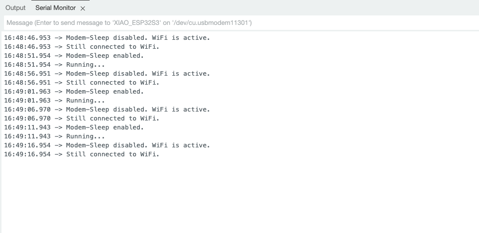
Sleep Function Application
With the above simple example, let's now take it a step further and use these sleep features on the ESP32 S3 Sense sensor.
Softare Preparetion
Before starting this article, please ensure you have completed some software installation preparations if you haven't yet utilized all the hardware features on the XIAO ESP32S3 Sense.
Here are introductions to three functionalities, and you can find more information through the following links:
-
Micrphone Use: Learn how to use the microphone on the XIAO ESP32S3 Sense to capture ambient sound levels and record audio.
-
MicroSD: Understand how to use a MicroSD card for data storage, ensuring you can save and retrieve files in your projects.
-
Camera Use: Master how to use the camera module on the XIAO ESP32S3 Sense to take photos and record videos.
Code Realization
- Deep-Sleep
- Light-Sleep
- Modem-Sleep
#include "esp_camera.h"
#include "FS.h"
#include "SD.h"
#include "SPI.h"

#define CAMERA_MODEL_XIAO_ESP32S3

#include "camera_pins.h"

unsigned long lastCaptureTime = 0;
int imageCount = 1;
bool camera_sign = false;
bool sd_sign = false;


void photo_save(const char * fileName) {
  camera_fb_t *fb = esp_camera_fb_get();
  if (!fb) {
    Serial.println("Failed to get camera frame buffer");
    return;
  }
  writeFile(SD, fileName, fb->buf, fb->len);

  esp_camera_fb_return(fb);

  Serial.println("Photo saved to file");
}

void writeFile(fs::FS &fs, const char * path, uint8_t * data, size_t len){
    Serial.printf("Writing file: %s\r\n", path);

    File file = fs.open(path, FILE_WRITE);
    if (!file) {
        Serial.println("Failed to open file for writing");
        return;
    }
    if (file.write(data, len) == len) {
        Serial.println("File written");
    } else {
        Serial.println("Write failed");
    }
    file.close();
}

void setup() {
  Serial.begin(115200);
  while (!Serial);

  camera_config_t config;
  config.ledc_channel = LEDC_CHANNEL_0;
  config.ledc_timer = LEDC_TIMER_0;
  config.pin_d0 = Y2_GPIO_NUM;
  config.pin_d1 = Y3_GPIO_NUM;
  config.pin_d2 = Y4_GPIO_NUM;
  config.pin_d3 = Y5_GPIO_NUM;
  config.pin_d4 = Y6_GPIO_NUM;
  config.pin_d5 = Y7_GPIO_NUM;
  config.pin_d6 = Y8_GPIO_NUM;
  config.pin_d7 = Y9_GPIO_NUM;
  config.pin_xclk = XCLK_GPIO_NUM;
  config.pin_pclk = PCLK_GPIO_NUM;
  config.pin_vsync = VSYNC_GPIO_NUM;
  config.pin_href = HREF_GPIO_NUM;
  config.pin_sscb_sda = SIOD_GPIO_NUM;
  config.pin_sscb_scl = SIOC_GPIO_NUM;
  config.pin_pwdn = PWDN_GPIO_NUM;
  config.pin_reset = RESET_GPIO_NUM;
  config.xclk_freq_hz = 20000000;
  config.frame_size = FRAMESIZE_UXGA;
  config.pixel_format = PIXFORMAT_JPEG;
  config.grab_mode = CAMERA_GRAB_WHEN_EMPTY;
  config.fb_location = CAMERA_FB_IN_PSRAM;
  config.jpeg_quality = 12;
  config.fb_count = 1;

  esp_err_t err = esp_camera_init(&config);
  if (err != ESP_OK) {
    Serial.printf("Camera init failed with error 0x%x", err);
    return;
  }

  camera_sign = true;

  if (!SD.begin(21)) {
    Serial.println("Card Mount Failed");
    return;
  }

  uint8_t cardType = SD.cardType();

  if (cardType == CARD_NONE) {
    Serial.println("No SD card attached");
    return;
  }

  Serial.print("SD Card Type: ");
  if (cardType == CARD_MMC) {
    Serial.println("MMC");
  } else if (cardType == CARD_SD) {
    Serial.println("SDSC");
  } else if (cardType == CARD_SDHC) {
    Serial.println("SDHC");
  } else {
    Serial.println("UNKNOWN");
  }

  sd_sign = true;

  Serial.println("Photos will begin shortly, please be ready.");
}

void loop() {
  if (camera_sign && sd_sign) {
    unsigned long now = millis();

    if ((now - lastCaptureTime) >= 60000) {
      char filename[32];
      sprintf(filename, "/image%d.jpg", imageCount);
      photo_save(filename);
      Serial.printf("Saved picture: %s\r\n", filename);
      Serial.println("Entering deep sleep for 10 seconds...");

      esp_sleep_enable_timer_wakeup(10000000);
      esp_deep_sleep_start();

    }
  }
}
Detailed Notes
This code implements an image capture system based on the ESP32 camera module, which can automatically take a photo every 60 seconds and save it to the SD card. In the void setup() function, the camera and SD card are initialized and the device status is confirmed; in the void loop() function, the camera is checked to see if it can take a picture, and if the condition is met, the photo_save() function is called to save the image and enter a deep sleep state for 10 seconds after saving to save energy.
#include <ESP_I2S.h>
#include <freertos/FreeRTOS.h>
#include <freertos/task.h>

I2SClass I2S;

const int sleepTime = 10000;

void i2sTask(void *pvParameters) {
  Serial.println("start collecting");
  for (int i = 0; i < 10; i++) {
    int sample = I2S.read();
    if (sample && sample != -1 && sample != 1) {
      Serial.println(sample);
    }
    vTaskDelay(pdMS_TO_TICKS(1000));
  }
  vTaskDelay(pdMS_TO_TICKS(3000));
  vTaskDelete(NULL);
}

void setup() {
  Serial.begin(115200);
  while (!Serial) {
    ;
  }

  I2S.setPinsPdmRx(42, 41);

  if (!I2S.begin(I2S_MODE_PDM_RX, 16000, I2S_DATA_BIT_WIDTH_16BIT, I2S_SLOT_MODE_MONO)) {
    Serial.println("Failed to initialize I2S!");
    while (1);
  }
}

void loop() {
  esp_sleep_enable_timer_wakeup(sleepTime * 1000);
  xTaskCreate(i2sTask, "I2S Task", 2048, NULL, 1, NULL);

  Serial.println("Going to sleep now...");
  esp_light_sleep_start();

  delay(1000);
}
Detailed Notes
This code implements the function of capturing audio data using the I2S interface. In the void setup() function, the serial port and the I2S interface are initialized; in the void loop() function, the wake-up timer is enabled and a task void i2sTask(void *pvParameters) is created, which is responsible for reading audio samples and printing valid data every second. After the task has run 10 times, it delays for 3 seconds and deletes itself.
#include "esp_camera.h"
#include <WiFi.h>

#define CAMERA_MODEL_XIAO_ESP32S3
#include "camera_pins.h"

const char *ssid = "******";
const char *password = "******";

void startCameraServer();
void setupLedFlash(int pin);

unsigned long lastCameraOperationTime = 0;
const unsigned long sleepDelay = 10000;

void setup() {
  Serial.begin(115200);
  Serial.setDebugOutput(true);
  Serial.println();

  camera_config_t config;
  config.ledc_channel = LEDC_CHANNEL_0;
  config.ledc_timer = LEDC_TIMER_0;
  config.pin_d0 = Y2_GPIO_NUM;
  config.pin_d1 = Y3_GPIO_NUM;
  config.pin_d2 = Y4_GPIO_NUM;
  config.pin_d3 = Y5_GPIO_NUM;
  config.pin_d4 = Y6_GPIO_NUM;
  config.pin_d5 = Y7_GPIO_NUM;
  config.pin_d6 = Y8_GPIO_NUM;
  config.pin_d7 = Y9_GPIO_NUM;
  config.pin_xclk = XCLK_GPIO_NUM;
  config.pin_pclk = PCLK_GPIO_NUM;
  config.pin_vsync = VSYNC_GPIO_NUM;
  config.pin_href = HREF_GPIO_NUM;
  config.pin_sccb_sda = SIOD_GPIO_NUM;
  config.pin_sccb_scl = SIOC_GPIO_NUM;
  config.pin_pwdn = PWDN_GPIO_NUM;
  config.pin_reset = RESET_GPIO_NUM;
  config.xclk_freq_hz = 20000000;
  config.frame_size = FRAMESIZE_UXGA;
  config.pixel_format = PIXFORMAT_JPEG;
  config.grab_mode = CAMERA_GRAB_WHEN_EMPTY;
  config.fb_location = CAMERA_FB_IN_PSRAM;
  config.jpeg_quality = 12;
  config.fb_count = 1;

  if (config.pixel_format == PIXFORMAT_JPEG) {
    if (psramFound()) {
      config.jpeg_quality = 10;
      config.fb_count = 2;
      config.grab_mode = CAMERA_GRAB_LATEST;
    } else {
      config.frame_size = FRAMESIZE_SVGA;
      config.fb_location = CAMERA_FB_IN_DRAM;
    }
  } else {
    config.frame_size = FRAMESIZE_240X240;
#if CONFIG_IDF_TARGET_ESP32S3
    config.fb_count = 2;
#endif
  }

#if defined(CAMERA_MODEL_ESP_EYE)
  pinMode(13, INPUT_PULLUP);
  pinMode(14, INPUT_PULLUP);
#endif

  esp_err_t err = esp_camera_init(&config);
  if (err != ESP_OK) {
    Serial.printf("Camera init failed with error 0x%x", err);
    return;
  }

  sensor_t *s = esp_camera_sensor_get();
  if (s->id.PID == OV3660_PID) {
    s->set_vflip(s, 1);
    s->set_brightness(s, 1);
    s->set_saturation(s, -2);
  }
  if (config.pixel_format == PIXFORMAT_JPEG) {
    s->set_framesize(s, FRAMESIZE_QVGA);
  }

#if defined(CAMERA_MODEL_M5STACK_WIDE) || defined(CAMERA_MODEL_M5STACK_ESP32CAM)
  s->set_vflip(s, 1);
  s->set_hmirror(s, 1);
#endif

#if defined(CAMERA_MODEL_ESP32S3_EYE)
  s->set_vflip(s, 1);
#endif

#if defined(LED_GPIO_NUM)
  setupLedFlash(LED_GPIO_NUM);
#endif

  WiFi.begin(ssid, password);
  WiFi.setSleep(false);

  while (WiFi.status() != WL_CONNECTED) {
    delay(500);
    Serial.print(".");
  }
  Serial.println("");
  Serial.println("WiFi connected");

  startCameraServer();

  Serial.print("Camera Ready! Use 'http://");
  Serial.print(WiFi.localIP());
  Serial.println("' to connect");
}

void loop() {
  delay(10000);

  if (WiFi.getSleep()) {
    Serial.println("WiFi is in sleep mode.");
  } else {
    Serial.println("WiFi is active.");
  }

  if (millis() - lastCameraOperationTime > sleepDelay) {
    WiFi.setSleep(true);
    Serial.println("No camera operation. WiFi is now in sleep mode.");
  } else {
    WiFi.setSleep(false);
  }
  cameraOperation();
}

void cameraOperation() {
  lastCameraOperationTime = millis();
}
Detailed Notes
This code implements the use of the ESP32 camera module for image capture and connection via Wi-Fi. In the void setup() function, the serial port, camera and Wi-Fi connection are initialized; if the initialization is successful, the program prints the Wi-Fi address for the user to connect. In void loop() function, the code checks the Wi-Fi status every 10 seconds, if there is no camera operation, the Wi-Fi will be set to sleep mode to save energy. Each call to the cameraOperation() function updates the time of the last operation to ensure that the Wi-Fi remains connected during the event.
These codes can not be used directly, you need to add the header file about the camera, please check the above example about XIAO ESP32 S3.
To conclude
Why use Deep Sleep mode
maximize power savings without compromising functionality, in order to extend the battery life of the device. Suitable scenarios: Applications where battery life is crucial, such as remote sensor nodes, wearable devices, and other low-power IoT devices. Although the wakeup time is relatively slow, this trade-off is worthwhile.
Why use Modem Sleep mode
optimize the power consumption of the wireless communication module, while still maintaining network connectivity. Suitable scenarios: Applications that need to maintain network connection but also require low power, such as intermittently working IoT devices. Modem Sleep can significantly reduce the power consumption of the wireless module while still providing fast wakeup response.
In summary
these three sleep modes provide developers with different power/performance trade-off options that can be flexibly chosen based on the specific requirements of the application. For devices with battery life requirements, Deep Sleep mode is a good choice; and for IoT devices that need to maintain network connectivity, Modem Sleep mode is the optimal choice.
Tech Support & Product Discussion
Thank you for choosing our products! We are here to provide you with different support to ensure that your experience with our products is as smooth as possible. We offer several communication channels to cater to different preferences and needs.