Pin Multiplexing (Arduino)

Seeed Studio XIAO RP2350 has rich interfaces. There are 19 digital I/O that can be used as PWM pins and 3 analog inputs that can be used as ADC pins. It supports four serial communication interfaces such as UART, I2C and SPI. This wiki will be helpful to learn about these interfaces and implement them in your next projects!
Preparation
Currently, there are some issues with the pin usage of the XIAO RP2350 due to compatibility problems. We have fixed this issue, and the Raspberry Pi official library has been merged. The current version is 4.2.0, and the update will be completed in the next version, 4.2.1.

In the meantime, please replace this file by going Arduino15/packages/rp2040/hardware/rp2040/4.2.0/variants/seeed_xiao_rp2350(Your Arduino Library Address) and clicking here to download the file. Once done, you can enjoy your work!

Digital
Hardware Preparation
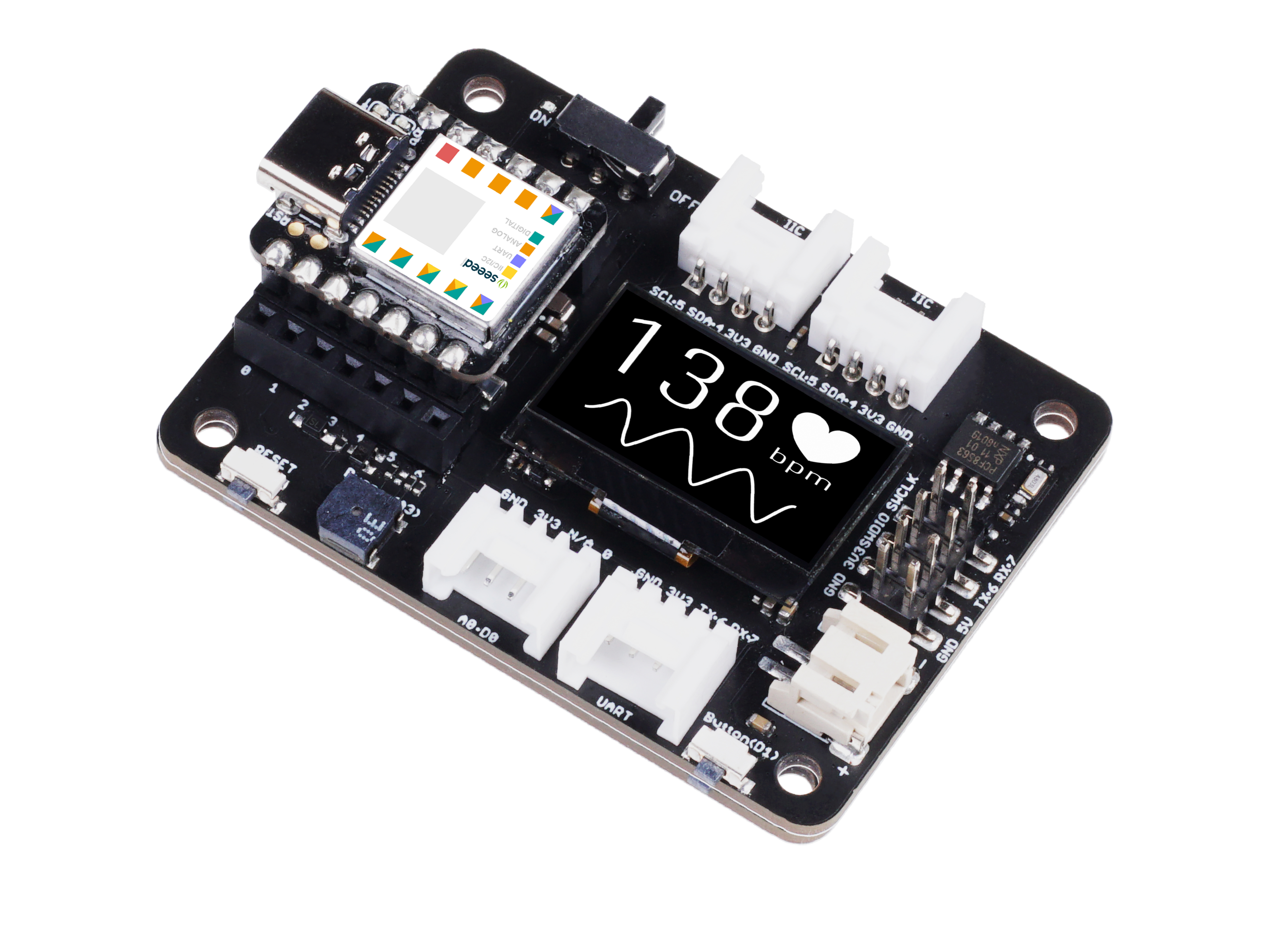
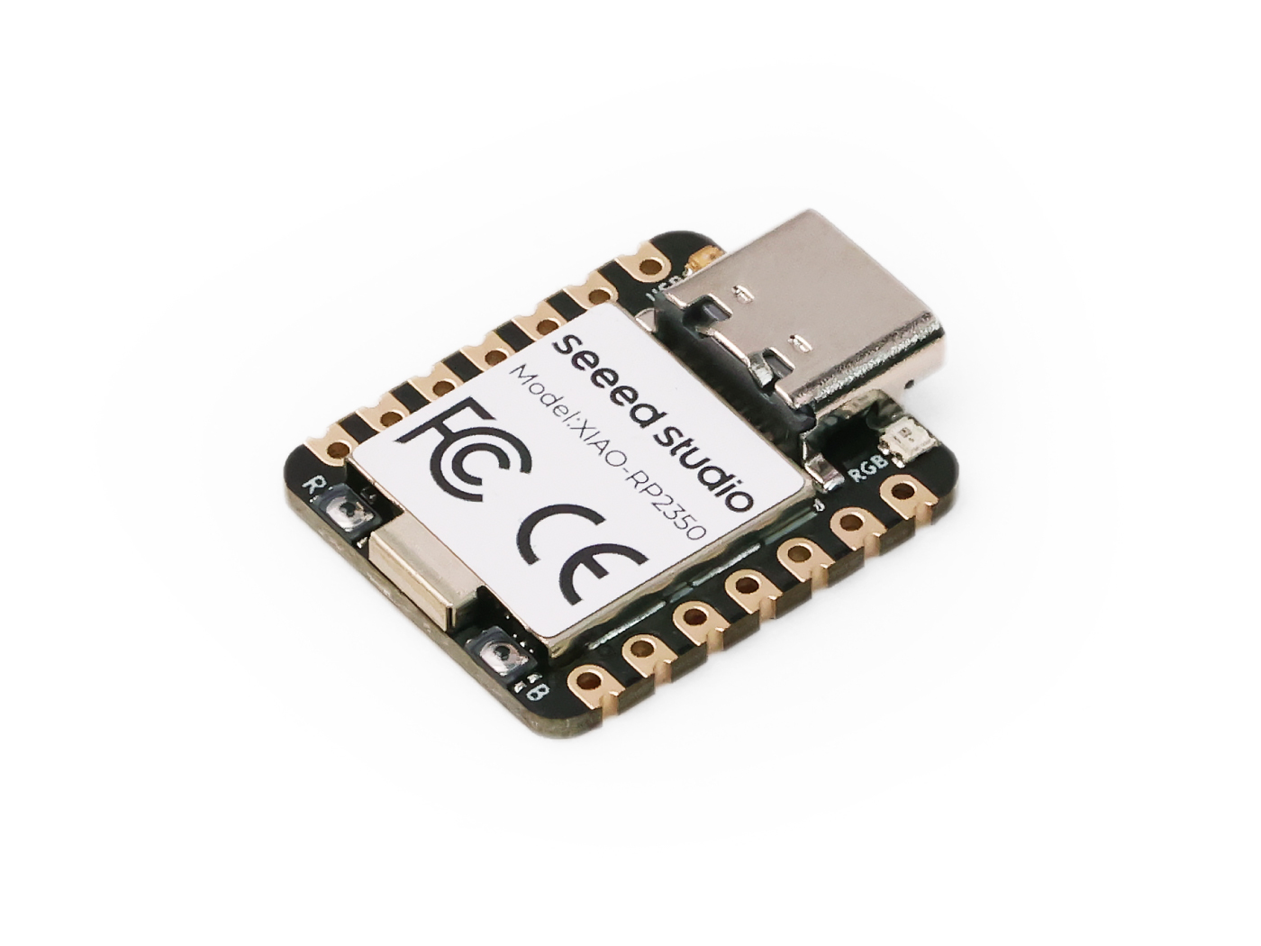
| Seeed Studio XIAO RP2350 | Seeed Studio Expansion Base for XIAO with Grove OLED | Grove - LED |
|---|---|---|
 |  |  |
Please install XIAO RP2350 onto the expansion board, and connect the Grove LED to the A0/D0 interface of the expansion board via a Grove cable. Finally, connect XIAO to the computer via a USB-C cable.
Software Implementation
In this example, we will implement control of a relay's on/off state using a button connected to the XIAO expansion board. When the button is pressed, the relay turns on, and when the button is released, the relay turns off.
//define which pin you use
int LED_BUILTIN = D0;
// the setup function runs once when you press reset or power the board
void setup() {
  // initialize digital pin LED_BUILTIN as an output.
  pinMode(LED_BUILTIN, OUTPUT);
}

// the loop function runs over and over again forever
void loop() {
  digitalWrite(LED_BUILTIN, HIGH);  // turn the LED on (HIGH is the voltage level)
  delay(1000);                      // wait for a second
  digitalWrite(LED_BUILTIN, LOW);   // turn the LED off by making the voltage LOW
  delay(1000);                      // wait for a second
}
Effect
If everything goes smoothly, after uploading the program, you should see the following effect.

Digital as PWM
All GPIO pins on XIAO RP2350 support PWM output. Therefore, you can use any pin to output PWM to adjust the brightness of lights, control servos, and other functions.
Hardware Preparation
| Seeed Studio XIAO RP2350 | Seeed Studio Expansion Base for XIAO with Grove OLED | Grove - LED |
|---|---|---|
 |  |  |
Please install XIAO RP2350 onto the expansion board, and connect the Grove LED to the A0/D0 interface of the expansion board via a Grove cable. Finally, connect XIAO to the computer via a USB-C cable.
Software Implementation
In this example, we will demonstrate how to use PWM output to control the brightness of a light.
int LED_pin = D0;    // LED connected to digital pin 10

void setup() {
  // declaring LED pin as output
  pinMode(LED_pin, OUTPUT);
}

void loop() {
  // fade in from min to max in increments of 5 points:
  for (int fadeValue = 0 ; fadeValue <= 255; fadeValue += 3) {
    // sets the value (range from 0 to 255):
    analogWrite(LED_pin, fadeValue);
    // wait for 30 milliseconds to see the dimming effect
    delay(30);
  }

  // fade out from max to min in increments of 5 points:
  for (int fadeValue = 255 ; fadeValue >= 0; fadeValue -= 3) {
    // sets the value (range from 0 to 255):
    analogWrite(LED_pin, fadeValue);
    // wait for 30 milliseconds to see the dimming effect
    delay(30);
  }
}
Effect
If the program runs successfully, you will see the following running effect.

Analog
XIAO MG24(Sense) Development Board have to 12 bit ADC for high-resolution reading of analog sensor values , it can help us to read more accurate values.
Next , We will choose two sensors to reflect the characteristics of ADC .
Hadware Preparation
| Seeed Studio XIAO RP2350 | Seeed Studio Expansion Base for XIAO with Grove OLED | Grove - Loudness Sensor |
|---|---|---|
 |  |  |
Software Implementation
int loudness;

void setup()
{
    Serial.begin(9600);// initialize Serial
}

void loop()
{
    loudness = analogRead(A0);// read analog data from A0 pin
    Serial.println(loudness);
    delay(200);
}
Effect
If everything goes smoothly, after uploading the program, you should see the following effect.

UART
When working with Arduino IDE, Serial communication is an essential part of many projects. To use Serial in Arduino IDE, you need to start by opening the Serial Monitor window. This can be done by clicking on the Serial Monitor icon in the toolbar or by pressing the Ctrl+Shift+M shortcut key.
General Usage
Some of the commonly used Serial functions include:
Serial.begin()-- which initializes the communication at a specified baud rate;Serial.print()-- which sends data to the Serial port in a readable format;Serial.write()-- which sends binary data to the Serial port;Serial.available()-- which checks if there is any data available to be read from the Serial port;Serial.read()-- which reads a single byte of data from the Serial port;Serial.flush()-- which waits for the transmission of outgoing serial data to complete.
By using these Serial functions, you can send and receive data between the Arduino board and your computer, which opens up many possibilities for creating interactive projects.
Here is an example program:
void setup() {
  // initialize serial communication at 9600 bits per second:
  Serial.begin(9600);
}

void loop() {
  // send data to the serial port
  Serial.println("Hello World!");

  // read data from the serial port
  if (Serial.available() > 0) {
    // read the incoming byte:
    char incomingByte = Serial.read();
    // print the incoming byte to the serial monitor:
    Serial.print("I received: ");
    Serial.println(incomingByte);
  }

  // wait for a second before repeating the loop
  delay(1000);
}
Effect
If everything goes smoothly, after uploading the program, you should see the following effect.

Usage of Serial1
According to the above XIAO RP2350 Pin diagrams for specific parameters, we can observe that there are TX and RX pin(D6,D7). The usage is also very similar, but we need to use serial port monitoring tool to monitor D6,D7 pins to get data. So next, we will use the D6,D7 pins to use serial1.
Normally, we use Serial to communicate between device and your computer so that we can knowing what happening in your program.
Base on that, you want to use this device to communicate with another devcie. In this case, we will use Serial1.
void setup() {
    Serial1.begin(115200);
}

void loop() {
  if(Serial1.available() > 0)
  {
    char incominByte = Serial1.read();
    Serial1.print("I received : ");
    Serial1.println(incominByte);
  }
  delay(1000);
}
Effect
If everything goes smoothly, after uploading the program, you should see the following effect.

I2C
XIAO RP2350 has an I2C interface that can be used for data transmission and parsing of many sensors, as well as for using some OLED screens.
Harware Preparation
| Seeed Studio XIAO RP2350 | Seeed Studio Expansion Base for XIAO with Grove OLED | Grove - DHT20 Temperature and Humidity Sensor |
|---|---|---|
 |  |  |
The DHT20 Sensor use I2C potocol, so we can use I2C port on XIAO Expansion Board to get sensor data.

Software Implementation
This example introduces how to get DHT20 sensor data via the Seeed Studio Expansion Base for XIAO RP2350.
Step 1. Install the Seeed Studio XIAO RP2350 on the Expansion board then conect the Type-C cable.
Step 2. Install the Grove Temperature And Humidity Sensor library.
Step 3. Add library to Arduino.

Step 4. Open DHTtester Demo from the library you just downloaded.

Because we use DHT20, so we need to uncomment DHT20 codes like the following code.
// Example testing sketch for various DHT humidity/temperature sensors
// Written by ladyada, public domain

#include "Grove_Temperature_And_Humidity_Sensor.h"

// Uncomment whatever type you're using!
//#define DHTTYPE DHT11   // DHT 11
// #define DHTTYPE DHT22   // DHT 22  (AM2302)
//#define DHTTYPE DHT21   // DHT 21 (AM2301)
//#define DHTTYPE DHT10   // DHT 10
#define DHTTYPE DHT20   // DHT 20

/*Notice: The DHT10 and DHT20 is different from other DHT* sensor ,it uses i2c interface rather than one wire*/
/*So it doesn't require a pin.*/
// #define DHTPIN 2     // what pin we're connected to(DHT10 and DHT20 don't need define it)
// DHT dht(DHTPIN, DHTTYPE);   //   DHT11 DHT21 DHT22
DHT dht(DHTTYPE);         //   DHT10 DHT20 don't need to define Pin

// Connect pin 1 (on the left) of the sensor to +5V
// Connect pin 2 of the sensor to whatever your DHTPIN is
// Connect pin 4 (on the right) of the sensor to GROUND
// Connect a 10K resistor from pin 2 (data) to pin 1 (power) of the sensor


#if defined(ARDUINO_ARCH_AVR)
    #define debug  Serial

#elif defined(ARDUINO_ARCH_SAMD) ||  defined(ARDUINO_ARCH_SAM)
    #define debug  SerialUSB
#else
    #define debug  Serial
#endif

void setup() {

    debug.begin(115200);
    debug.println("DHTxx test!");
    Wire.begin();

    /*if using WIO link,must pull up the power pin.*/
    // pinMode(PIN_GROVE_POWER, OUTPUT);
    // digitalWrite(PIN_GROVE_POWER, 1);

    dht.begin();
}

void loop() {
    float temp_hum_val[2] = {0};
    // Reading temperature or humidity takes about 250 milliseconds!
    // Sensor readings may also be up to 2 seconds 'old' (its a very slow sensor)


    if (!dht.readTempAndHumidity(temp_hum_val)) {
        debug.print("Humidity: ");
        debug.print(temp_hum_val[0]);
        debug.print(" %\t");
        debug.print("Temperature: ");
        debug.print(temp_hum_val[1]);
        debug.println(" *C");
    } else {
        debug.println("Failed to get temprature and humidity value.");
    }

    delay(1500);
}
Effect
If everything goes smoothly, after uploading the program, you should see the following effect.

SPI
The XIAO RP2350 chip integrates multiple peripherals, including an SPI interface that can be used to connect external SPI devices such as flash memory, displays, sensors, and more. The XIAO RP2350 also supports high-speed SPI transfer mode, which can achieve a maximum SPI transfer rate of 80 MHz, meeting the data transfer needs of most SPI devices.
Hadware Preparation
| Seeed Studio XIAO RP2350 | Grove - OLED Display 1.12 (SH1107) V3.0 - SPI/IIC |
|---|---|
 | _V3.0/img/10402050_Main-02.png) |
After preparing the hardware as mentioned above, use jumper wires to connect the SPI interface of the XIAO and OLED. Please refer to the following table to wire.
| XIAO RP2350 | OLED Display |
|---|---|
| D8 | SCL |
| D10 | SI |
| D5 | RES |
| D4 | D/C |
| D7 | CS |
| VCC(VBUS) | 5V |
| GND | GND |
Software Implementation
Next, we will take the following program as an example to introduce how to use the SPI interface to control the OLED screen display.
Install the u8g2 library.
#include <Arduino.h>
#include <U8g2lib.h>
#include <SPI.h>
#include <Wire.h>

U8G2_SH1107_128X128_1_4W_HW_SPI u8g2(U8G2_R3, /* cs=*/ D7, /* dc=*/ D4, /* reset=*/ D5);

void setup(void) {
  u8g2.begin();
}

void loop(void) {
  u8g2.firstPage();

  do {
    u8g2.setFont(u8g2_font_luBIS08_tf);
    u8g2.drawStr(0,24,"Hello Seeed!");
  } while ( u8g2.nextPage() );
}
In the setup() function, the U8G2_SH1107_128X128_1_4W_HW_SPI class is instantiated with the appropriate constructor arguments that specify the pins used for chip select (cs), data/command (dc), and reset. Then, the u8g2.begin() function is called to initialize the display.
In the loop() function, the display is updated with new content using the u8g2.firstPage(), u8g2.setFont(), and u8g2.drawStr() functions. The u8g2.firstPage() function sets up the display buffer for writing, while u8g2.nextPage() displays the updated content. The do-while loop ensures that the content is displayed continuously until the program is stopped.
Overall, this code demonstrates how to use the U8g2 library to control an OLED display and display text on it.

Finish up
You have learned the basic functions of the XIAO RP2350 pins. Now, let's have fun with it~

Tech Support & Product Discussion
Thank you for choosing our products! We are here to provide you with different support to ensure that your experience with our products is as smooth as possible. We offer several communication channels to cater to different preferences and needs.