Getting Started with AI Assistant
Introduction
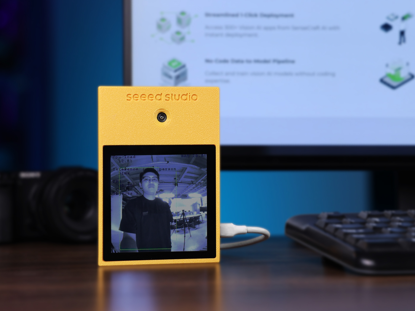
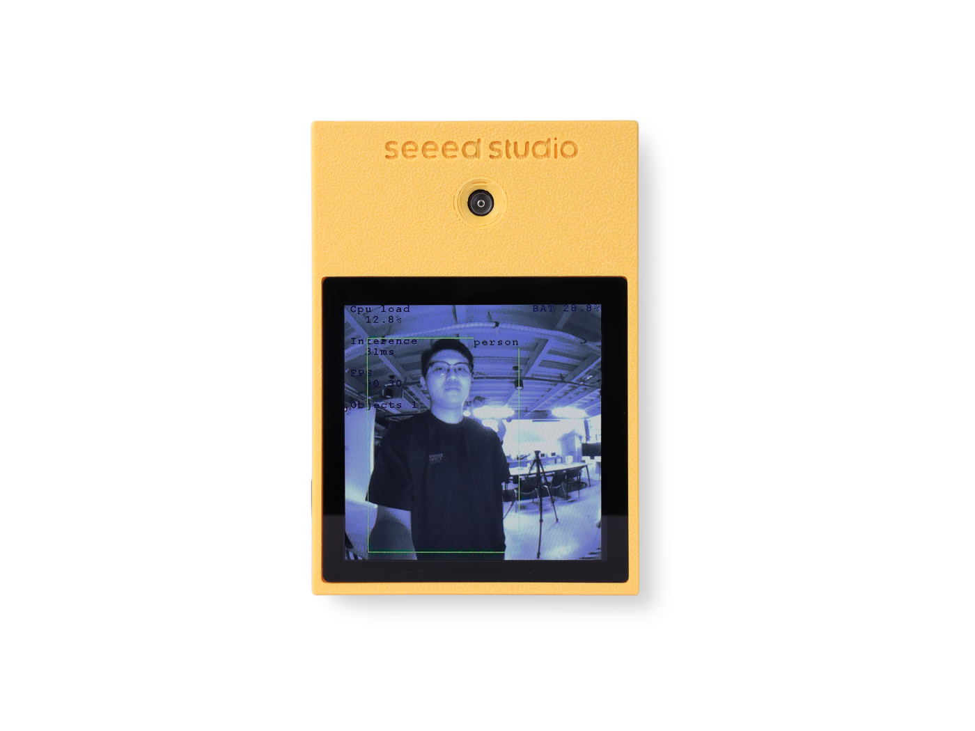
The AI Assistant development kit, jointly created by Seeed Studio and STMicroelectronics. This is a development platform designed for cutting-edge edge AI applications. Centered around the high-performance STM32N657 MCU with its integrated ST Neural-ART AI accelerator, it perfectly blends powerful AI computing capabilities with the classic MCU advantages of low power consumption, a small form factor, and cost-effectiveness. The kit comes equipped with an onboard global shutter camera, an IMU sensor with an AI processing unit, a high-definition touchscreen, and a Wi-Fi module, offering a complete hardware and software solution for developing next-generation smart vision and voice interaction products.
Features
- Feature 1:Flagship AI Microcontroller Powered by the ST STM32N657, featuring a high-performance Arm® Cortex®-M55 core and an integrated ST Neural-ART NPU that delivers up to 600 GOPS for efficient AI model acceleration.
- Feature 2: Professional-grade Vision Sensor Equipped with an ST VD55G1 global shutter camera, providing crisp, distortion-free images of fast-moving objects, which is critical for high-accuracy computer vision tasks.
- Feature 3: Intelligent Sensing with ISPU Features an LSM6DSO16IS IMU with a built-in Intelligent Sensor Processing Unit (ISPU), enabling ultra-low power gesture and activity recognition without waking the main processor.
- Feature 4: Rich Interactive Peripherals Integrates a 4.0-inch 480x480 capacitive touch display, a high-fidelity digital microphone, and an audio codec, providing a complete hardware foundation for developing interactive AI applications out of the box.
- Feature 5: Comprehensive Connectivity Includes an onboard Wi-Fi module for seamless IoT connectivity, alongside a USB-C port and multiple expansion headers for maximum development flexibility.
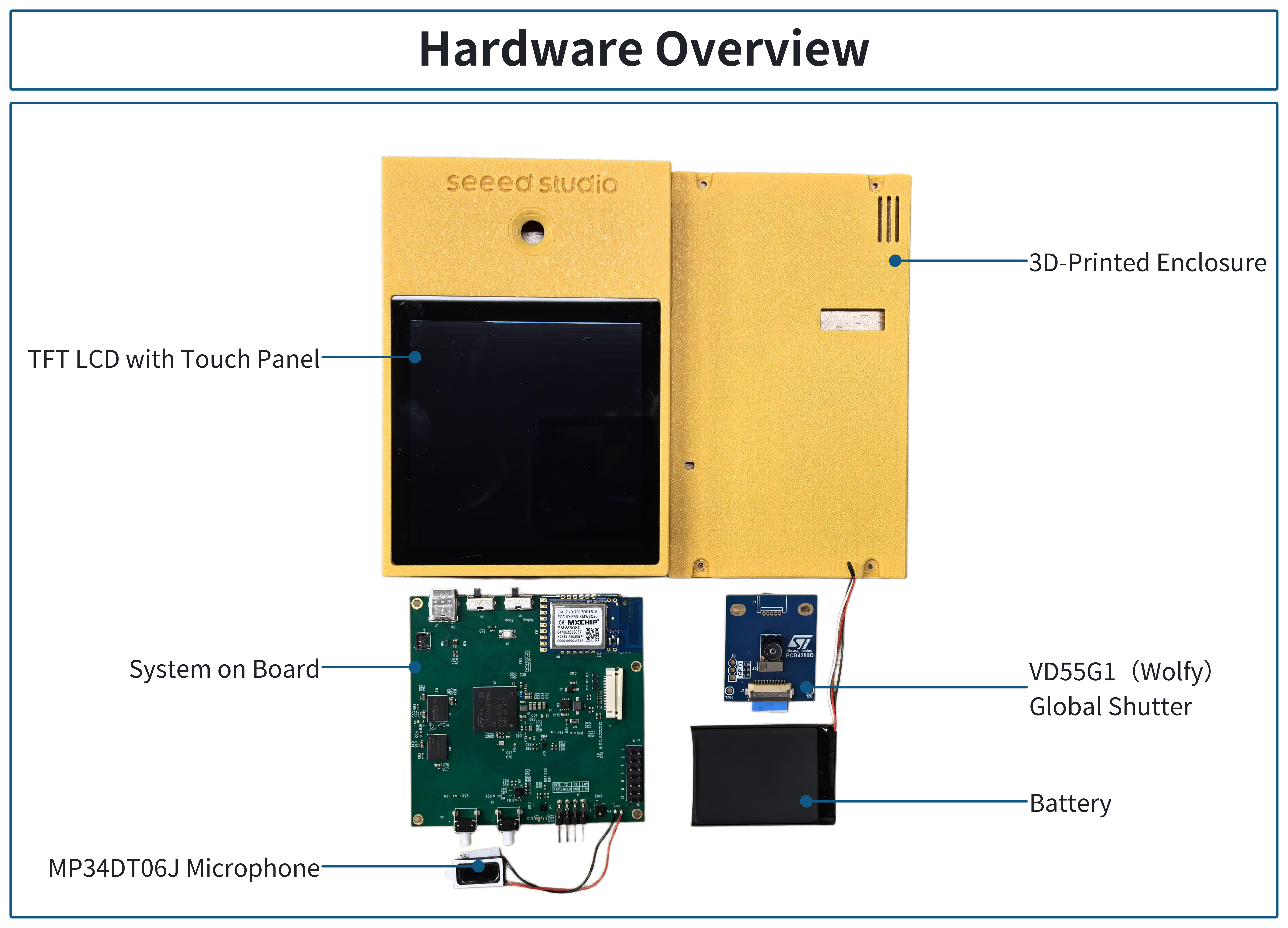
Hardware Overview
Before everything starts, it is quite essential to have some basic parameters of the product. The following table provides information about the characteristics of AI Assistant.
| Category | Feature | Specification |
|---|---|---|
| Core System | Main Controller | STMicroelectronics STM32N657X0H3Q |
| Core Architecture | Arm® Cortex®-M55 | |
| Neural Processing Unit | ST Neural-ART, 600 GOPS | |
| External Memory | 128MB NOR Flash, 32MB DRAM | |
| Sensors | Camera | STMicroelectronics VD55G1 (800x700, Global Shutter) |
| IMU | STMicroelectronics LSM6DSO16IS (6-axis with built-in ISPU) | |
| Magnetometer | STMicroelectronics LIS2MDL | |
| Peripherals | Display | 4.0" TFT LCD (480x480), Capacitive Touch |
| Audio | Cirrus Logic WM8994 Codec & ST MP34DT06JTR Digital Mic | |
| Connectivity | Wireless | MXCHIP EMW3080 Wi-Fi Module |
| Interfaces | USB-C x1, SWD Port x1, Mic Expansion x1, RPi Camera Interface x1 | |
| Mechanical & Power | Dimensions (Casing) | 130mm x 90mm |
| Power Supply | 5V via USB-C or Lithium Battery Port |
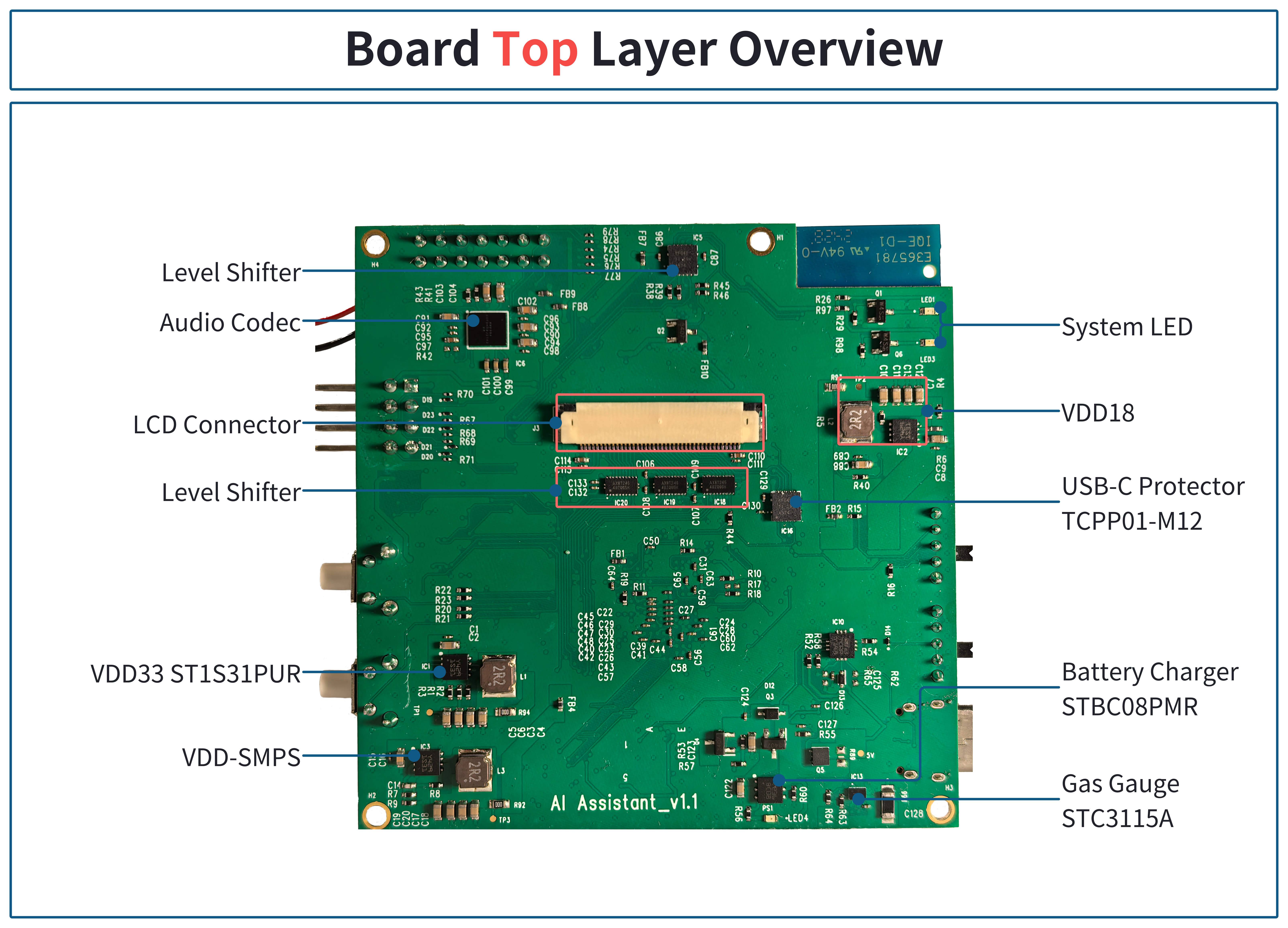
Board Top Layer Overview
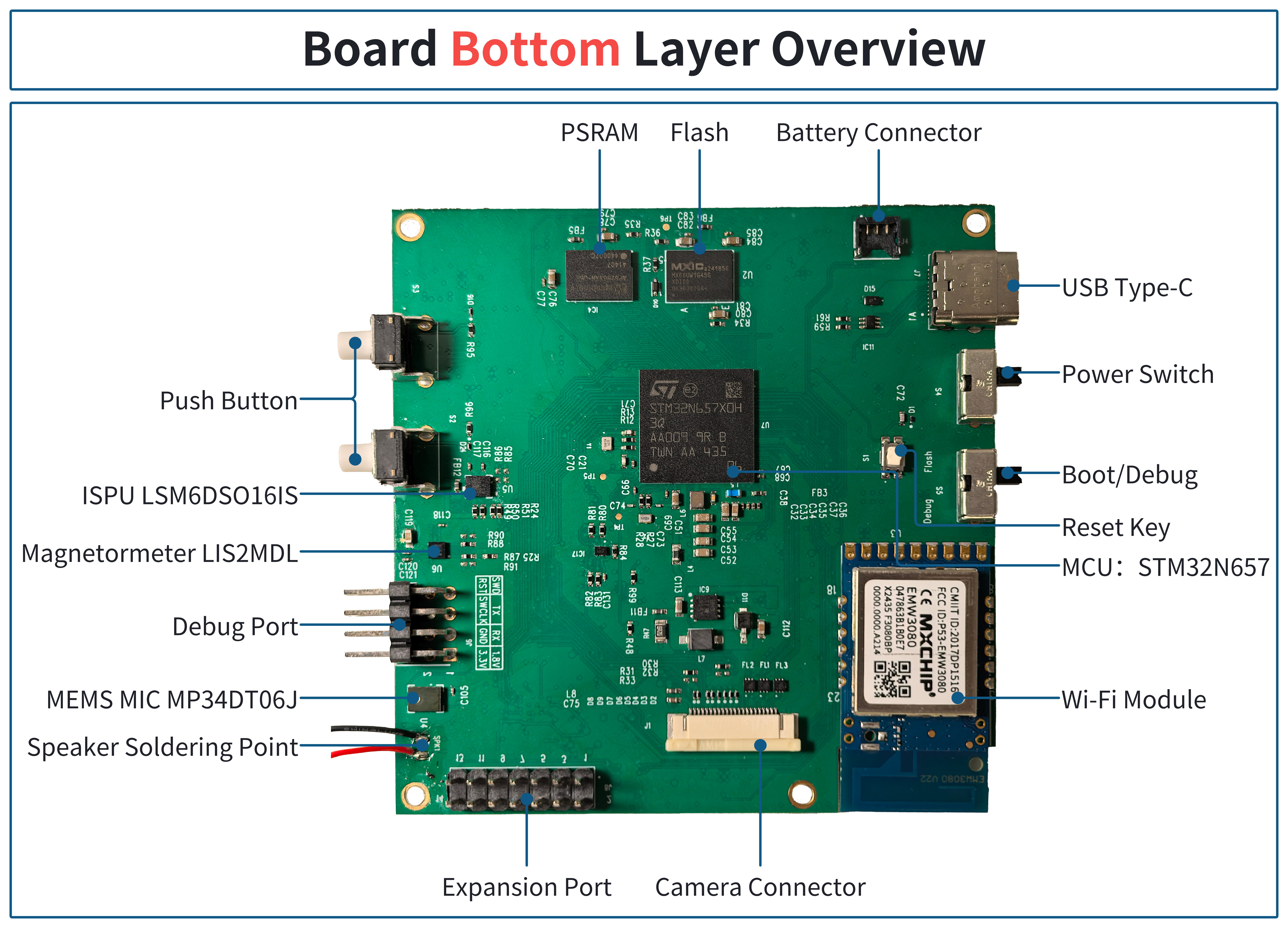
Board Bottom Layer Overview
Start with AI Assistant Reference Application
To get started, clone the repository from the GitHub linkgit clone https://github.com/stm32-hotspot/STM32N6-AI-Assistant-People-Detection.git into your preferred local folder.
Computer Vision application to enable the deployment of object detection models on AI Assistant board. It's based on the official release of n6-ai-people-detection-v1.0.0 application package for STM32N6570-DK board.
This application is prebuilt with a people detection model "TinyYOLOv2".
This section provides an overview of the application. Additional documentation is available in the Additional Documentation of The Application.
Features Demonstrated in This Example
- Multi-threaded application flow (Azure RTOS ThreadX)
- NPU accelerated quantized AI model inference
- Dual DCMIPP pipes
- DCMIPP crop, decimation, downscale
- LTDC dual-layer implementation
- DCMIPP ISP usage
- Dev mode
- Boot from External Flash
Hardware Support
-
AI Assistant Kit
-
3 Cameras are supported:
- MB1854B IMX335
AI Assistant kit with VD55G1 Camera.
Tools Version
- STM32CubeIDE (STM32CubeIDE 1.18.0)
- STM32CubeProgrammer (v2.18.0)
- STEdgeAI (v2.1.0)
ST-Link Connection
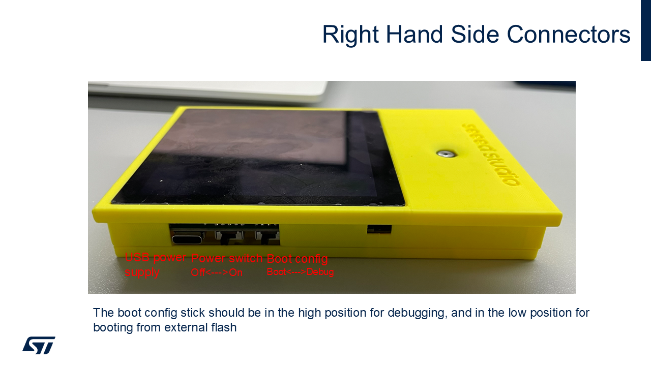
Right Hand Side Connectors
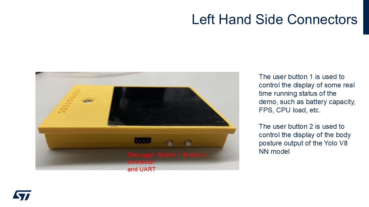
Left Hand Side Connectors
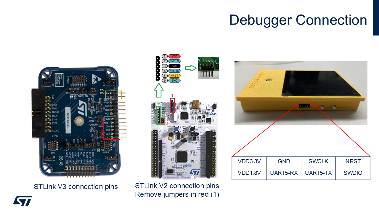
Debugger Connection
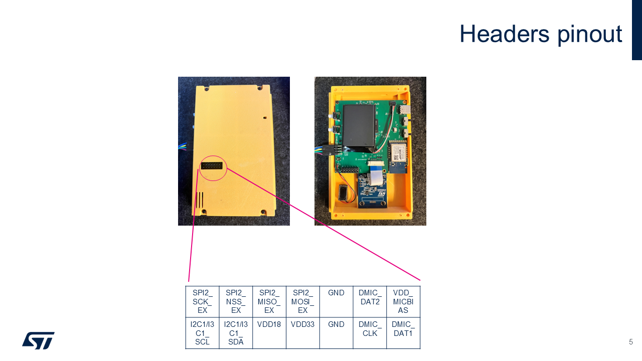
Headers pinout
Boot Modes
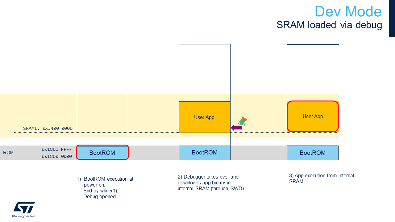
The STM32N6 does not have any internal flash. To retain your firmware after a reboot, you must program it in the external flash. Alternatively, you can load your firmware directly from SRAM (dev mode). However, in dev mode, if you turn off the board, your program will be lost.
Boot modes:
- Dev mode: load firmware from debug session in RAM (boot switch to the right)
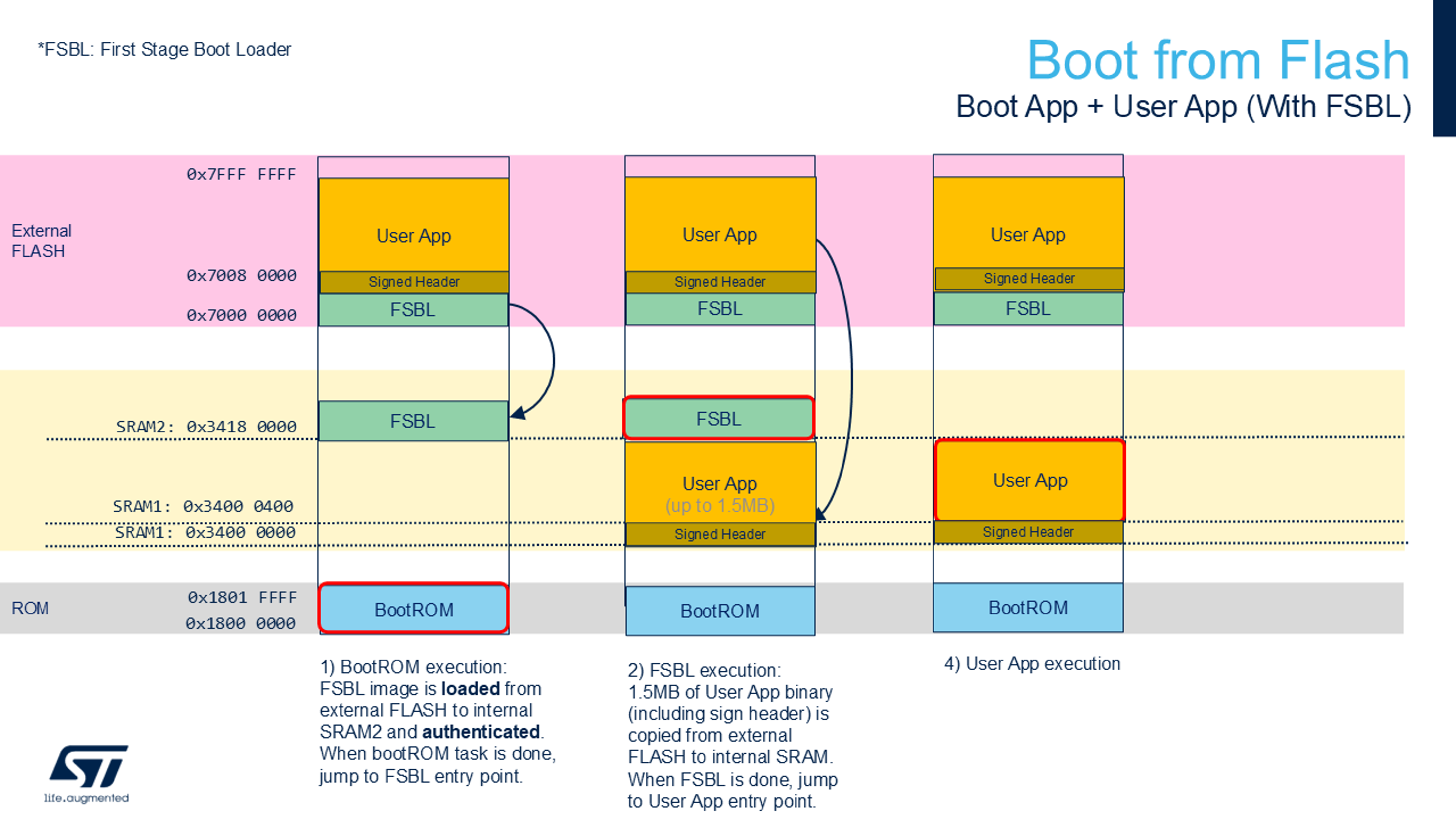
- Boot from flash: Program firmware in external flash (boot switch to the left)
Quick start Using Prebuilt Binaries
Flash Prebuilt Binaries
Three binaries must be programmed into the board's external flash using the following procedure:
- Switch the BOOT switch to the up position.
- Program
Binary/ai_assistant_fsbl.hex(To be done once) (First stage boot loader). - Program
Binary/network_data.hex(parameters of the networks; To be changed only when the network is changed). - Program
Binary/AI_Assistant_Ref_Project.hex(firmware application). - Switch the BOOT switch to the down position.
- Perform a power down/up sequence.
How to Program Hex Files Using STM32CubeProgrammer UI
See How to Program Hex Files STM32CubeProgrammer.
How to Program Hex Files Using Command Line
Make sure to have the STM32CubeProgrammer bin folder added to your path.
export DKEL="<STM32CubeProgrammer_N6 Install Folder>/bin/ExternalLoader/MX66UW1G45G_STM32N6570-DK.stldr"

# First Stage Boot Loader
STM32_Programmer_CLI -c port=SWD mode=HOTPLUG -el $DKEL -hardRst -w Binary/ai_fsbl.hex

# Network Parameters and Biases
STM32_Programmer_CLI -c port=SWD mode=HOTPLUG -el $DKEL -hardRst -w Binary/network_data.hex

# Application Firmware
STM32_Programmer_CLI -c port=SWD mode=HOTPLUG -el $DKEL -hardRst -w Binary/x-cube-n6-ai-people-detection.hex
Quick start Using Source Code
Before building and running the application, you have to program network_data.hex (model weights and biases).
This step only has to be done once unless you change the AI model. See Quick start Using Prebuilt Binaries for details.
More information about boot modes is available at Boot Overview .
Application Build and Run - Dev Mode
Make sure to have the switch to the right side.
STM32CubeIDE
Double click on STM32CubeIDE/.project to open the project in STM32CubeIDE. Build and run with the build and run buttons.
Makefile
Before running the commands below, be sure to have the commands in your PATH.
- Build the project using the provided
Makefile:
make -j8
- Open a GDB server connected to the STM32 target:
ST-LINK_gdbserver -p 61234 -l 1 -d -s -cp <path-to-stm32cubeprogramer-bin-dir> -m 1 -g
- In a separate terminal session, launch a GDB session to load the firmware image into the device memory:
$ arm-none-eabi-gdb build/Project.elf
(gdb) target remote :61234
(gdb) monitor reset
(gdb) load
(gdb) continue
Application Build and Run - Boot from Flash
Make sure to have the switch on the right side.
STM32CubeIDE
Double click on STM32CubeIDE/.project to open project in STM32CubeIDE. Build with build button.
Makefile
Before running the commands below, be sure to have them in your PATH.
- Build project using the provided
Makefile:
make -j8
Once your app is built with Makefile, STM32CubeIDE, or EWARM, you can add a signature to the bin file:
STM32_SigningTool_CLI -bin build/Project.bin -nk -t ssbl -hv 2.3 -o build/Project_sign.bin
You can program the signed bin file at the address 0x70100000.
export DKEL="<STM32CubeProgrammer_N6 Install Folder>/bin/ExternalLoader/MX66UW1G45G_STM32N6570-DK.stldr"

# Adapt build path to your IDE
STM32_Programmer_CLI -c port=SWD mode=HOTPLUG -el $DKEL -hardRst -w build/Project_sign.bin 0x70100000
Note: Only the App binary needs to be programmed if the FSBL and network_data.hex were previously programmed.
Known Issues and Limitations
- (NN_WIDTH * NN_BPP) must be a multiple of 16.
- (LCD_BG_WIDTH * 2) must be a multiple of 16.
Additional Documentation of The Application
Application Overview
Application Data Flow
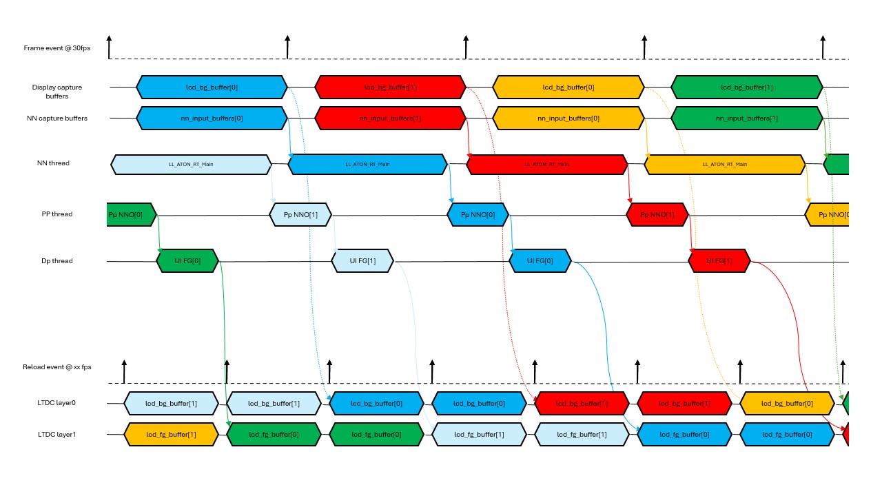
Application Timing Diagram
Memory Footprint Details
Read-Only Data
| Name | Size | Location | Notes |
|---|---|---|---|
network_data | 10.59 MB | .rodata | FLASH xSPI2 8b |
Read-Write Data
| Name | Size | Location | Notes |
|---|---|---|---|
lcd_bg_buffer | 2300 KB | .psram_bss | PSRAM / (800x480x2) x 3 / RGB565 |
lcd_fg_buffer | 1500 KB | .psram_bss | PSRAM / (800x480x2) x 2 / ARGB4444 |
nn_input_buffers | 294 KB | .psram_bss | PSRAM / (224x224x3) x 2 / RGB888 |
nn_output_buffers | 12 KB | .bss | SRAM / 5880 x 2 |
activations | 507 KB | 0x34200000 | NPURAMS |
threads stacks | 20 KB | .bss | SRAM / 4096 * 5 |
DCMIPP and ISP
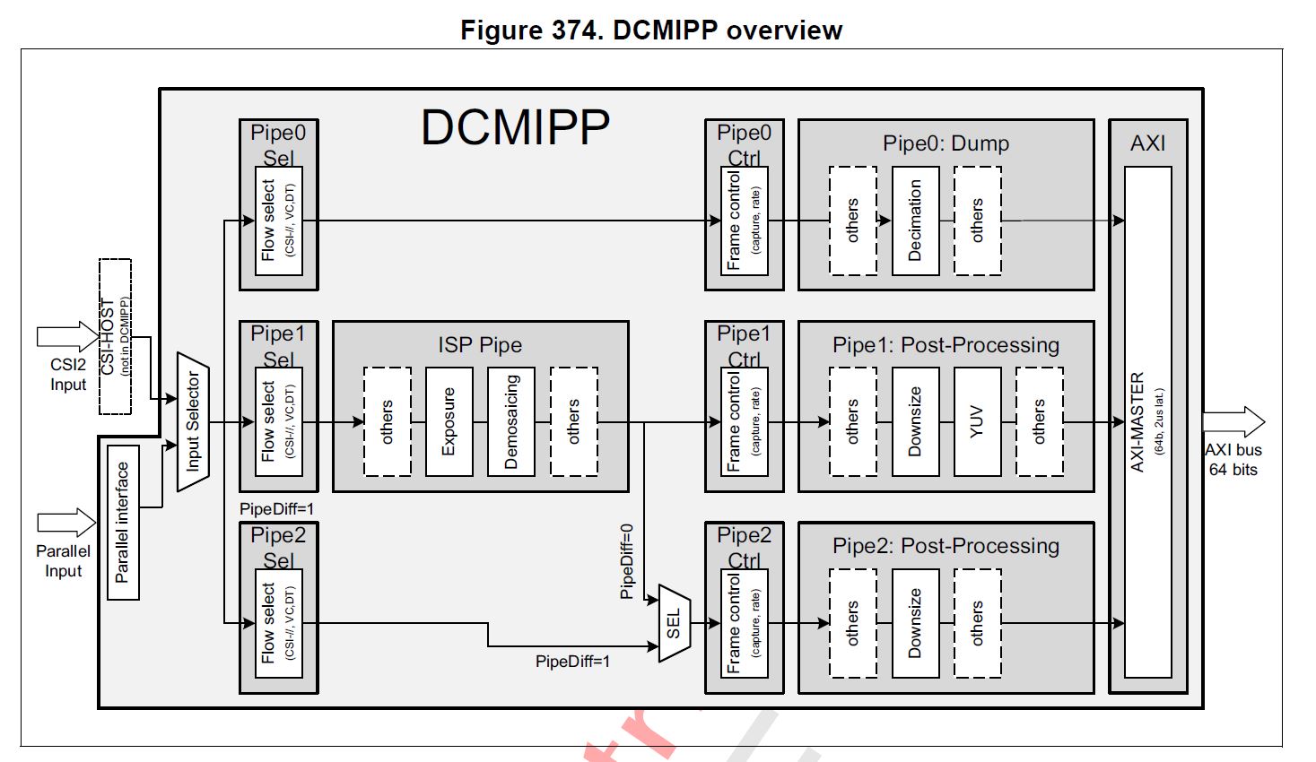
DCMIPP Overview
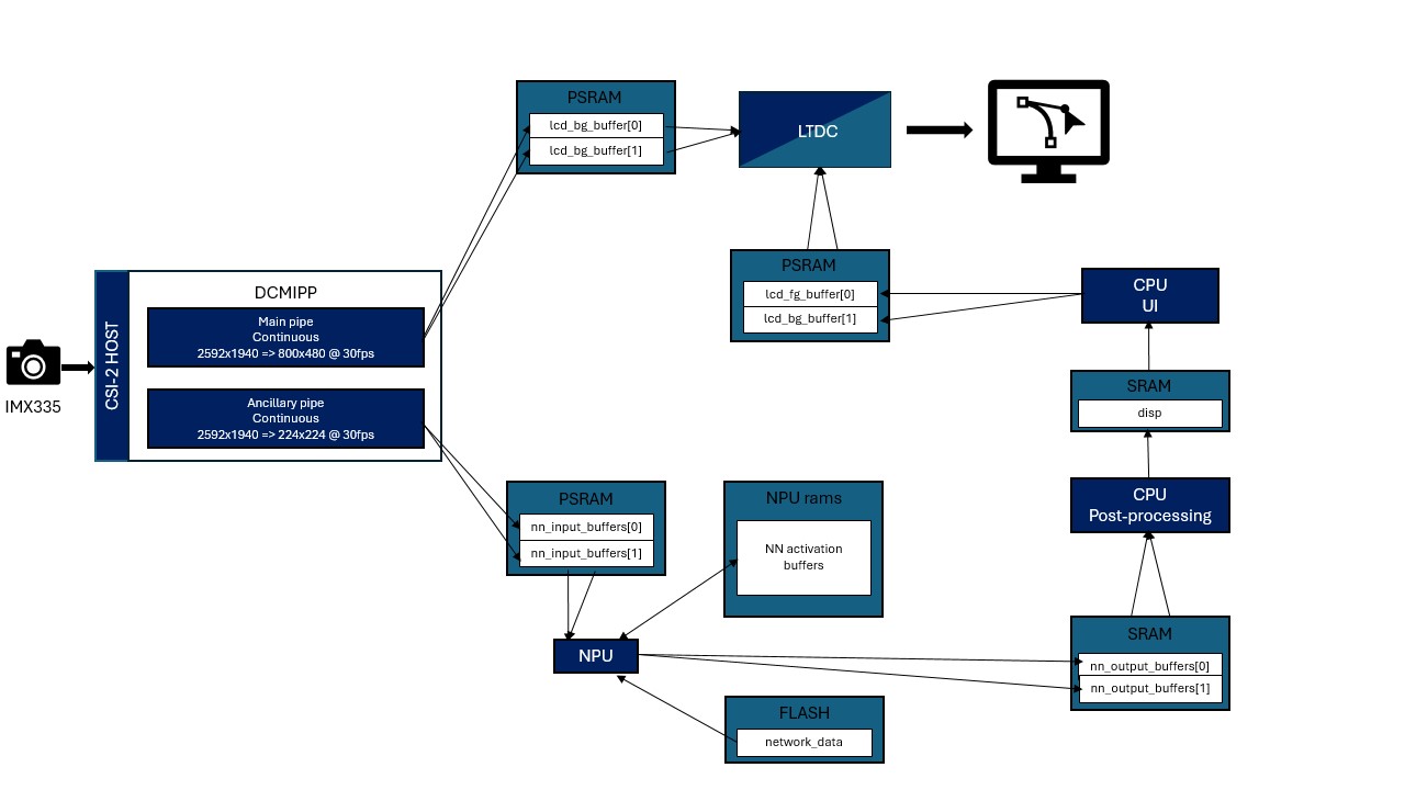
- Pipe 1 is enabled using
CMW_CAMERA_Start(DCMIPP_PIPE1, *ptr_dst, CAMERA_MODE_CONTINUOUS);to continuously transmit images from imx335 to the DISPLAY_BUFFER_NB bufferedlcd_bg_buffer[]. Note thatptr_dstwill be updated at pipe1 frame_event. - Pipe 2 is enabled using
CMW_CAMERA_Start(DCMIPP_PIPE2, *ptr_dst, CAMERA_MODE_CONTINUOUS);to continuously transmit images from imx335 to the double bufferednn_input_buffers[]. Note thatptr_dstwill be updated at pipe2 frame_event. This allows dropping the previous frame if the buffer is still in use by the nn thread. - For each capture, the ISP configuration is updated to enhance the image quality depending on the illumination conditions. It is initialized through
ISP_Initand then executed withISP_BackgroundProcess.
For more details on DCMIPP, see the Digital Camera Interface Pixel Pipeline (DCMIPP) section in the STM32N6 Reference Manual.
Boot Overview
Dev Mode
Boot from Flash with First Stage Boot Loader
Build Options
Some features are enabled using build options or by using app_config.h:
This documentation explains those features and how to modify them.
Camera Orientation
Cameras allow flipping the image along two axes.
CMW_MIRRORFLIP_MIRROR: Selfie modeCMW_MIRRORFLIP_FLIP: Flip upside downCMW_MIRRORFLIP_FLIP_MIRROR: Flip both axesCMW_MIRRORFLIP_NONE: Default
-
Open app_config.h.
-
Change the
CAMERA_FLIPdefine:
/* Defines: CMW_MIRRORFLIP_NONE; CMW_MIRRORFLIP_FLIP; CMW_MIRRORFLIP_MIRROR; CMW_MIRRORFLIP_FLIP_MIRROR; */

#define CAMERA_FLIP CMW_MIRRORFLIP_NONE
Deploy Your TFLite Model
To run your own object detection model, follow these steps:
- 1. Generate C-Model from TFLite Model
- 2. Program Your Network Data
- 3. Provide NN Information in
app_config.h - 4. Build Application
- 5. Run Application
1. Generate C-Model from TFLite Model
To generate the network.c, network_ecblobs.h and the file containing network parameters, you must install STM32Cube.AI
-
Add
<folderInstall>/Utilities/<your_os>/to your path to havestedgeaiknown by your bash. -
Add
<stm32cubeide_folderInstall>/plugins/com.st.stm32cube.ide.mcu.externaltools.gnu-tools-for-<plugin_version>/tools/binto your path to havearm-none-eabi-objcopyknown by your bash.
cd Model
stedgeai generate --no-inputs-allocation --no-outputs-allocation --model quantized_tiny_yolo_v2_224_.tflite --target stm32n6 --st-neural-art default@user_neuralart.json
cp st_ai_output/network_ecblobs.h .
cp st_ai_output/network.c .
cp st_ai_output/network_atonbuf.xSPI2.raw network_data.xSPI2.bin
arm-none-eabi-objcopy -I binary network_data.xSPI2.bin --change-addresses 0x70380000 -O ihex network_data.hex
You can find the following script at Model/generate-n6-model.sh
2. Program Your Network Data
Now you can program your network data in external flash.
export DKEL="<STM32CubeProgrammer_N6 Install Folder>/bin/ExternalLoader/MX66UW1G45G_STM32N6570-DK.stldr"

# Weights and parameters
STM32_Programmer_CLI -c port=SWD mode=HOTPLUG -el $DKEL -hardRst -w Model/network_data.hex
3. Provide NN Information in app_config.h
You need to edit the last lines of Inc/app_config.h to make the app compatible with your network.
Post Process Type
This application supports four types of object detection post-processing. You can select one of these. Edit POSTPROCESS_TYPE with one of these values.
#define POSTPROCESS_OD_YOLO_V2_UF       (10) /* Yolov2 postprocessing; Input model: uint8; output: float32         */
#define POSTPROCESS_OD_YOLO_V5_UU       (11) /* Yolov5 postprocessing; Input model: uint8; output: uint8           */
#define POSTPROCESS_OD_YOLO_V8_UF       (12) /* Yolov8 postprocessing; Input model: uint8; output: float32         */
#define POSTPROCESS_OD_YOLO_V8_UI       (13) /* Yolov8 postprocessing; Input model: uint8; output: int8            */
NN Size Info
Edit your NN_WIDTH and NN_HEIGHT.
WARNING: NN_WIDTH * NN_BPP must be a multiple of 16.
WARNING: Only RGB888 format has been tested.
Class Labels
Modify the NB_CLASSES and classes_table with your own class labels and number of classes.
Display Delay
Using DISPLAY_DELAY allows delaying the displayed image so that the displayed information from the model is aligned with the displayed image. Adjust this value according to the model inference time.
Configure Post Process Parameters Through User File
To change your post-process parameters, you need to edit the Inc/postprocess_conf.h.
Documentation of the post-processing library is available at Postprocess lib.
You can edit IOU thresholds, anchor values, and other parameters.
Some of these parameters need to be aligned with your model (number of classes, for example).
Configure Output Buffer Size
Edit NN_BUFFER_OUT_SIZE so it has the size in bytes of your output tensor.
4. Build Application
Once your network data has been programmed (step 2) and network details configured (step 3), you can build your application by following:
5. Run Application
Dev Mode
See the Application build and run section for more details.
Boot from Flash
See Program app in external flash to program your firmware.
How to Program Hex Files
- Ensure the board is in dev mode (boot switch in dev mode position).
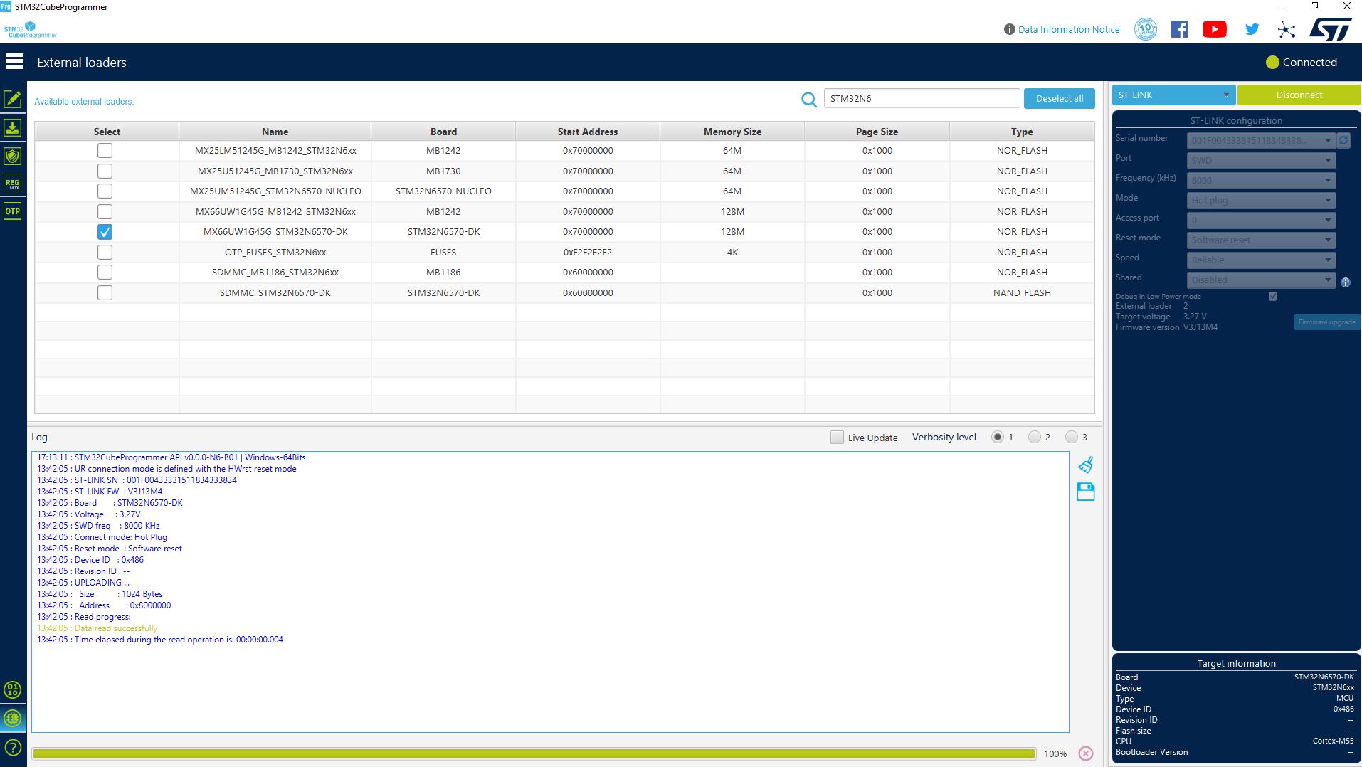
- Open STM32CubeProgrammer.
- Select the MX66UW1G45G_STM32N6570-DK flash through the External loaders tab.
- ST-Link configuration: set mode to "Hot plug".
- Connect the board.
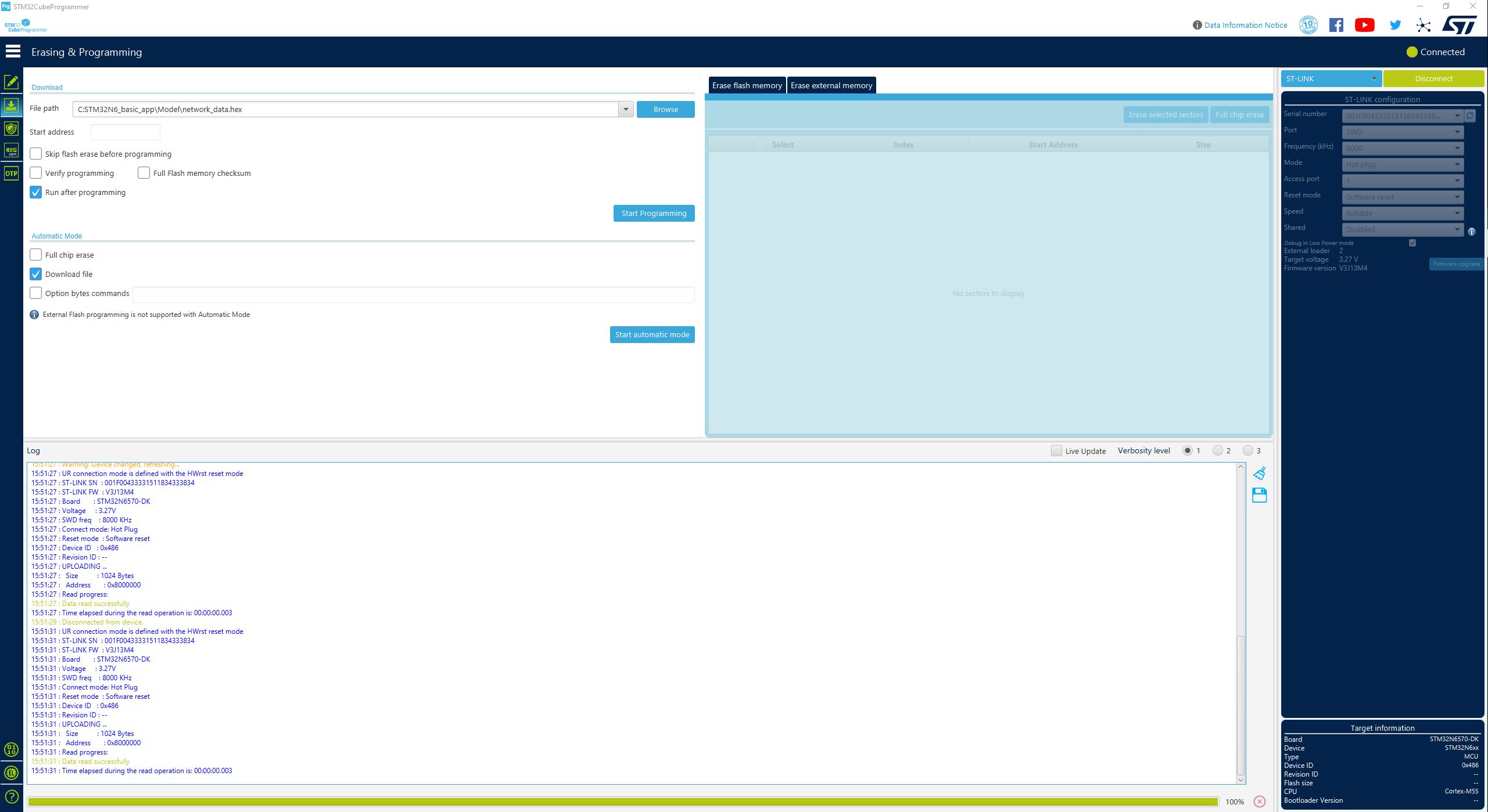
- From the "Erasing & programming" tab, select the
Binary/ai_assistant_fsbl.hexfile. - Wait for flashing to complete.
- From the "Erasing & programming" tab, select the
Binary/network_data.hexfile. - Wait for flashing to complete.
- From the "Erasing & programming" tab, select the
Binary/AI_Assistant_Ref_Project.hexfile. - Wait for flashing to complete.
Resources
- [PDF] AI Assistant Schematic
Tech Support
This product is supported by STMicroelectronics. For any technical issues or inquiries, please contact: Technical Support Contact: [Click here]