Robotics J501 Hardware and Getting Started
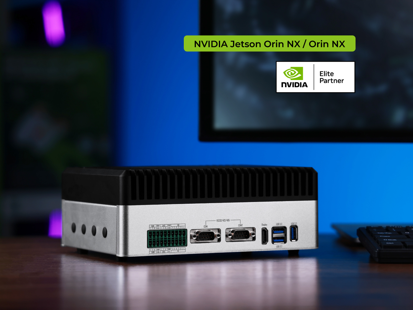
The reComputer Robotics J501 is a high-performance edge AI carrier board designed for advanced robotics and industrial applications. Compatible with NVIDIA Jetson AGX Orin modules (32GB/64GB) in MAXN mode, it delivers up to 275 TOPS of AI performance.
Equipped with extensive connectivity options—including 1x 10GbE and 4x 1GbE Ethernet ports, dual M.2 Key M slots for NVMe SSDs, M.2 slots for 5G and Wi-Fi/BT modules, multiple USB 3.0 ports, four CAN interfaces (2 native + 2 SPI-to-CAN), GMSL2 camera expansion, and comprehensive I/O including DI/DO, I2S, UART, and RS485—it serves as a powerful robotic brain for complex multi-sensor fusion and real-time AI processing.
Pre-installed with JetPack 6.2.1 and Linux BSP, it ensures seamless deployment. Supporting frameworks like NVIDIA Isaac ROS, Hugging Face, PyTorch, and ROS 2/1, the J501 bridges large language model-driven decision-making with physical robotics control, accelerating development of autonomous robots with ready-to-use interfaces and optimized AI frameworks.
Key Features
- High-performance AI: Up to 275 TOPS with Jetson AGX Orin 32/64GB modules, Ampere GPU and DLA engines
- Rich connectivity: Dual M.2 Key M (NVMe); Key E (WiFi/BT) + Key B (5G); 1x 10GbE + 4x 1GbE; 3x USB 3.0; 2x USB-C
- Quad CAN-FD: 2x native + 2x SPI-to-CAN interfaces with electrical isolation
- GMSL2 vision: Single GMSL2 interface (1x) for high-speed camera connection
- Industrial design: 19-48V DC input; -10~60°C operation; isolated interfaces; pre-installed JetPack 6.2.1
- Robotics ready: ROS 2/1, Isaac ROS support; DI/DO, I2S, UART, RS485; AMR and automation optimized
Specifications
| Jetson AGX Orin System on Module | ||
|---|---|---|
| Specifications | reComputer Robotics J5011 | reComputer Robotics J5012 |
| Module | NVIDIA Jetson AGX Orin 32GB | NVIDIA Jetson AGX Orin 64GB |
| AI Performance | 200 TOPS | 275 TOPS |
| GPU | 1792-core NVIDIA Ampere @ 930 MHz | 2048-core NVIDIA Ampere @ 1.3 GHz |
| CPU | 8-core Arm Cortex-A78AE @ 2.0 GHz | 12-core Arm Cortex-A78AE @ 2.2 GHz |
| Memory | 32GB 256-bit LPDDR5 @ 204.8 GB/s | 64GB 256-bit LPDDR5 @ 204.8 GB/s |
| Video Encoder | 1x 4K60 / 3x 4K30 / 6x 1080p60 / 12x 1080p30 (H.265) | 2x 4K60 / 6x 4K30 / 8x 1080p60 / 16x 1080p30 (H.265) |
| Video Decoder | 1x 8K30 / 2x 4K60 / 4x 4K30 / 9x 1080p60 / 18x 1080p30 (H.265) | 1x 8K30 / 3x 4K60 / 7x 4K30 / 11x 1080p60 / 22x 1080p30 (H.265) |
| CSI Camera | Up to 6 cameras (16 via virtual channels) 16 lanes MIPI CSI-2 D-PHY 2.1 (up to 40Gbps) / C-PHY 2.0 (up to 164Gbps) | |
| Mechanical | 100mm x 87mm 699-pin Molex Mirror Mezz Connector Integrated Thermal Transfer Plate | |
| Carrier Board | ||
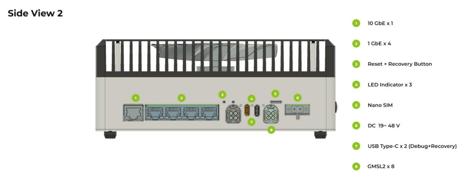
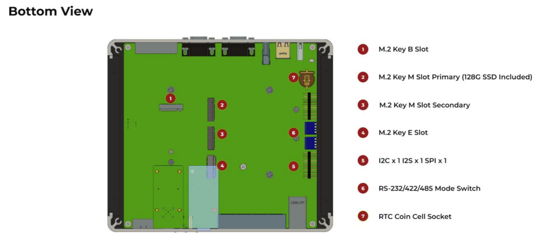
| Storage | 2x M.2 Key-M (NVMe 2280 SSD) 1x M.2 Key-B (for 4G/5G modules) | |
| Networking | 1x M.2 Key-E (WiFi/BT) 1x RJ45 10GbE + 4x RJ45 1GbE | |
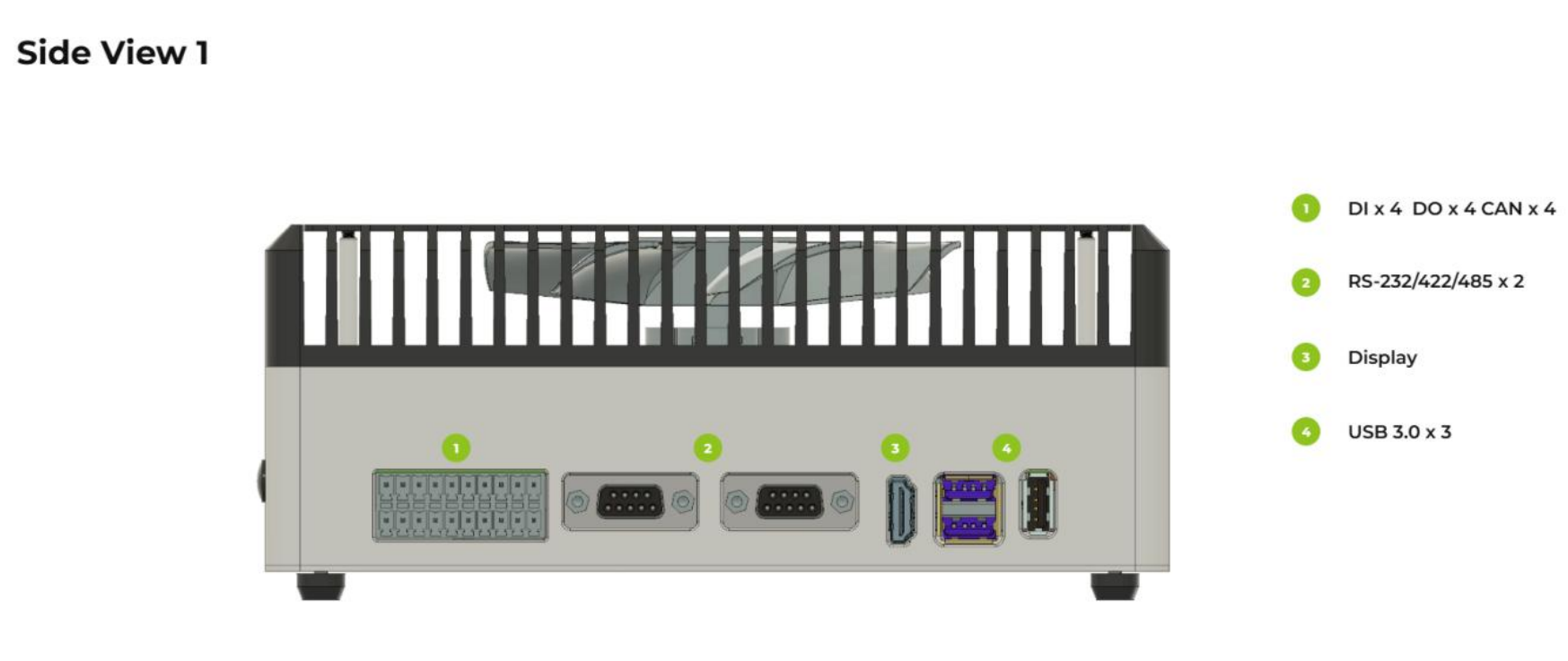
| USB | 3x USB 3.0 Type-A 1x USB 3.0 Type-C (Recovery) 1x USB 2.0 Type-C (Debug UART) | |
| DI/DO/CAN | 1x 2x10P 3.81mm Terminal Block - 4x DI @12V + 4x DO @40V + 4x CAN (CAN-FD supported, electrically isolated) | |
| GMSL | 2x Mini-Fakra Connector (For 8x GMSL2 Cameras) (optional) | |
| Serial | 2x DB9 (RS232/422/485) | |
| Display | 1x HDMI 2.1 | |
| Fan | 1×12 V (2.54 mm), 1×5 V (1.25 mm JST) | |
| Button | 1x Recovery + 1x Reset | |
| LED | 3x LED (PWR, SSD, and User LED) | |
| RTC | 1x CR1220 Battery Holder, 1x RTC 2-Pin Header | |
| Power Input | 19-48V DC via 5.08mm Terminal Block(Power adapter not included) | |
| Power Consumption | Jetson AGX Orin module: Up to 60W (MAXN mode) Total system peak: 75W (including peripherals) | |
| Software | Jetpack 6.2.1 | |
| Mechanical | Dimensions: 210mm x 180mm x 87mm (with stands) | |
| Warranty | 2 Years | |
| Certification | RoHS, REACH, CE, FCC, UKCA, KC | |
GMSL Extension Board Specifications (Optional)
| De-serializer | MAX96712 |
|---|---|
| GMSL Interface | 2x Robotics-Fakra Male Connector |
| GMSL Input | Up to 8x GMSL2 Cameras |
| Connection Method | GMSL2 Fakra 1-to-4 M-M Cable |
| POC Interface Feature | Supports simultaneous power and data transmission |
Hardware Overview
📦 Flash JetPack OS
Supported Module
Prerequisites
- Ubuntu host PC
- reComputer Robotics J501
- USB Type-C data transmission cable
We recommend that you use physical Ubuntu host devices instead of virtual machines. Please refer to the table below to prepare the host machine.
| JetPack Version | Ubuntu Version (Host Computer) | ||
| 18.04 | 20.04 | 22.04 | |
| JetPack 6.x | ✅ | ✅ | |
Prepare the Jetpack Image
Here, we need to download the system image to our Ubuntu PC corresponding to the Jetson module we are using:
| Jetpack Version | Jetson Module | GMSL | Download Link1 | SHA256 |
|---|---|---|---|---|
| 6.2.1 | AGX Orin 64GB | ✅ | Download | 46167c63566fa07d9882be338becd44 7021c8fc0a73da18d0291c414cf5c6f4a |
| AGX Orin 32GB | ✅ | Download | e868fd8c7ad05d3acc8c9808f42e1835 28f11df14f48cb6ae16464adb4f23d1f |
The Jetpack6 image file is approximately 14.2GB in size and should take around 60 minutes to download. Please kindly wait for the download to complete.
To verify the integrity of the downloaded firmware, you can compare the SHA256 hash value.
On an Ubuntu host machine, open the terminal and run the command sha256sum <File> to obtain the SHA256 hash value of the downloaded file. If the resulting hash matches the SHA256 hash provided in the wiki, it confirms that the firmware you downloaded is complete and intact.
⚙️ All .dts files and other source code for SEEED's Jetson carrier boards can be downloaded from Linux_for_Tegra
Enter Force Recovery Mode
Before we can move on to the installation steps, we need to make sure that the board is in force recovery mode.
Step-by-Step
Step 1. Connect a USB Type-C data transmission cable between USB2.0 DEVICE port and the Ubuntu host PC.
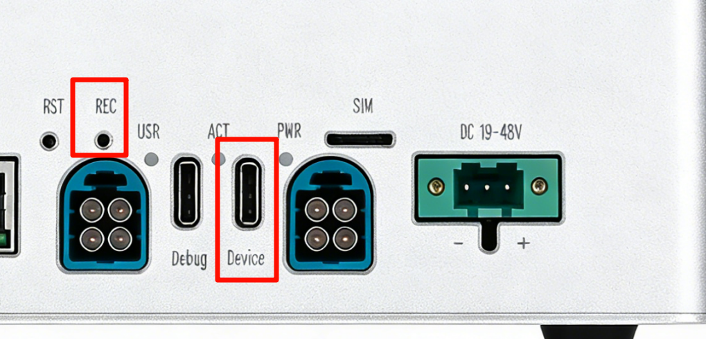
Step 2. Use a pin and insert into the RECOVERY hole to press recovery button and while holding this.
Step 3. Connect the power supply.
Step 4. Release the recovery button.
Step 5. On the Linux host PC, open a Terminal window and enter the command lsusb. If the returned content has one of the following outputs according to the Jetson SoM you use, then the board is in force recovery mode.
- For AGX Orin 32GB: 0955:7223 NVidia Corp
- For AGX Orin 64GB: 0955:7023 NVidia Corp
The below image is for AGX Orin 32GB:

Flash to Jetson
Step 1: Extract the downloaded image file:
cd <path-to-image>
sudo tar xpf mfi_xxxx.tar.gz
# For example: sudo tar xpf mfi_recomputer-robo-agx-orin-32g-j501-6.2.1-36.4.4-2026-02-11.tar.gz
Step 2: Execute the following command to flash jetpack system to the NVMe SSD:
cd mfi_xxxx
# For example: cd mfi_recomputer-robo-agx-orin-j501x
sudo ./tools/kernel_flash/l4t_initrd_flash.sh --flash-only --massflash 1 --network usb0  --showlogs
You will see the following output if the flashing process is successful
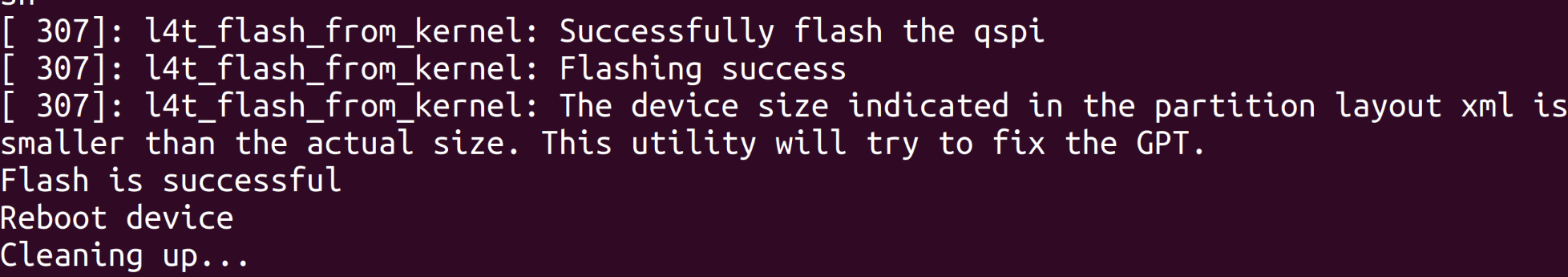
The flash command may run for 2-10 minutes.
Step 3: Connect the Robotics J501 to a display using the PD to HDMI adapter to connect to a display that supports HDMI input, or directly connect to a display that supports PD input using the PD cable, and finish the initial configuration setup:
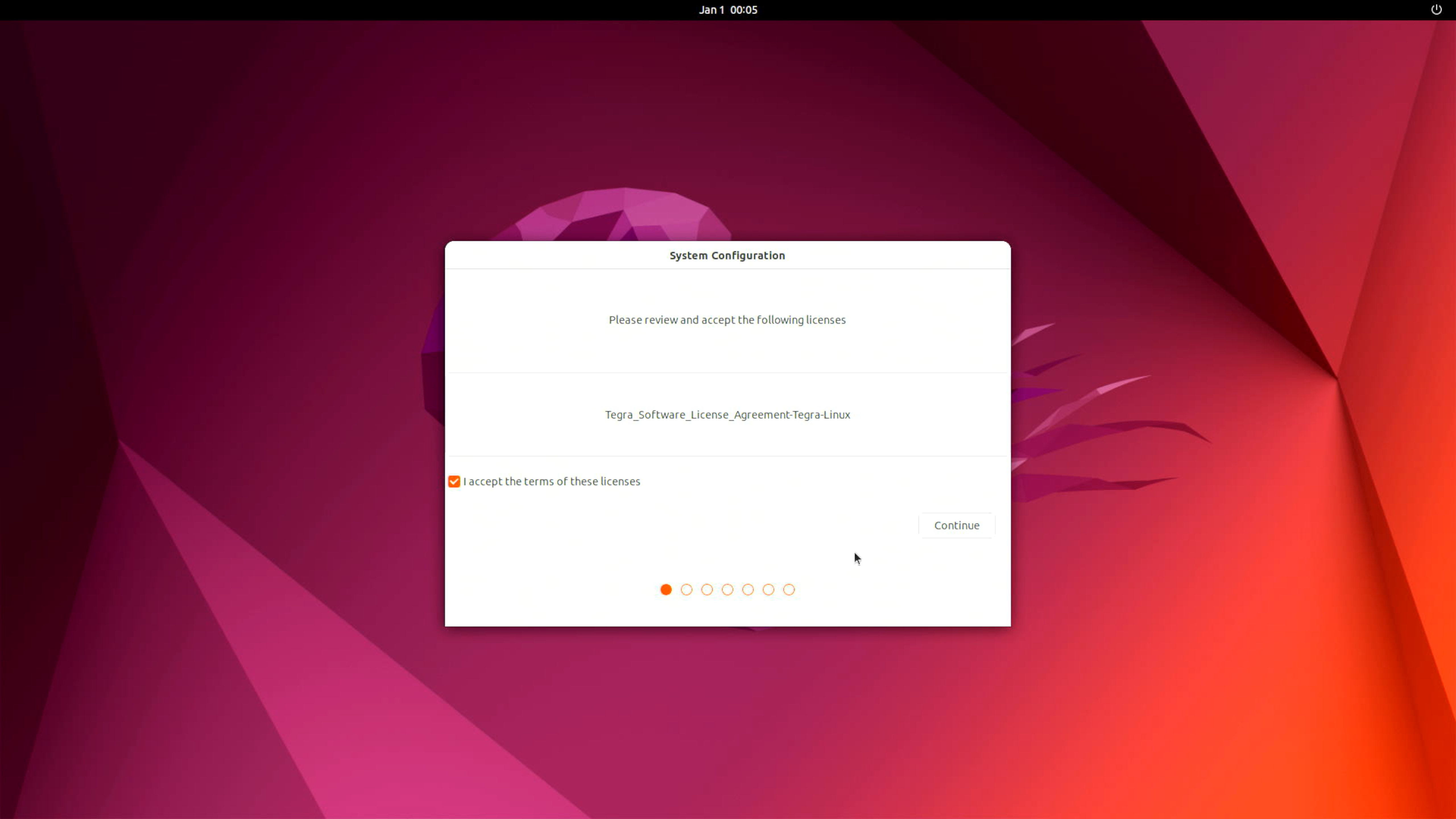
Please complete the System Configuration according to your needs.
🔌 Interfaces Usage
The following will introduce the various interfaces of the Robotics J501 board and how to use them.
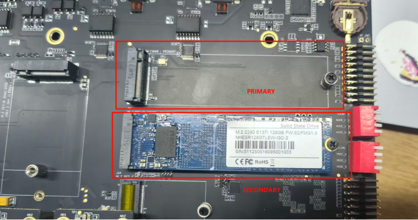
M.2 Key M
The J501 includes dual M.2 Key M slots supporting PCIe Gen4x4 NVMe SSDs for high-speed storage expansion.
Supported SSD are as follows
- 128GB NVMe M.2 PCle Gen3x4 2280 Internal SSD
- 256GB NVMe M.2 PCle Gen3x4 2280 Internal SSD
- 512GB NVMe M.2 PCle Gen3x4 2280 Internal SSD
- 1TB NVMe M.2 PCle Gen3x4 2280 Internal SSD
- 2TB NVMe M.2 PCle Gen3x4 2280 Internal SSD
Hardware Connection
Usage Instruction
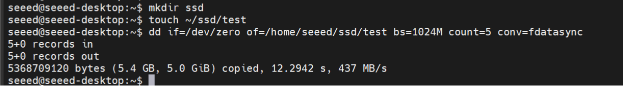
Open the terminal in Jetson device and enter the following command to test the SSD's read and write speed.
Step 1. Create test directory and file:
mkdir ssd
touch ~/ssd/test
Step 2. Test write performance:
dd if=/dev/zero of=/home/$USER/ssd/test bs=1024M count=5 conv=fdatasync
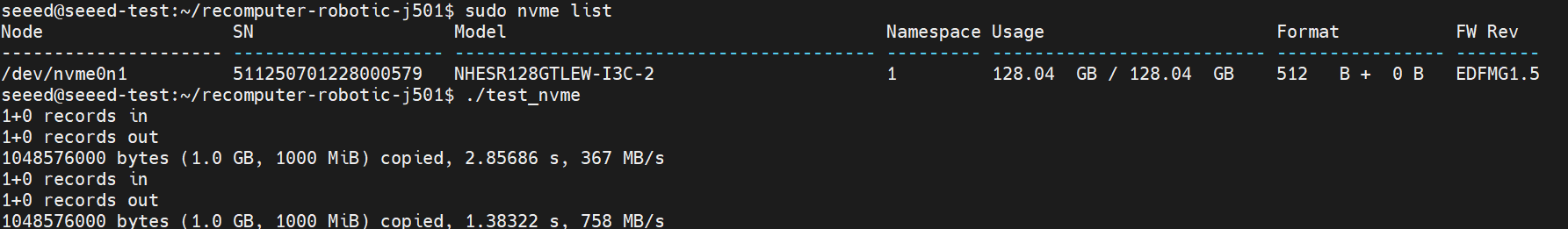
Step 3. Check SSD info:
nvme list
Please run sudo rm /home/$USER/ssd/test command to delete the cache files after the test is complete.
M.2 Key E (WiFi/BT)
The M.2 Key E slot supports Wi-Fi 6 and Bluetooth 5.x modules for wireless connectivity.
Hardware Connection
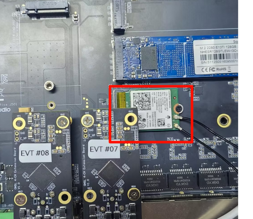
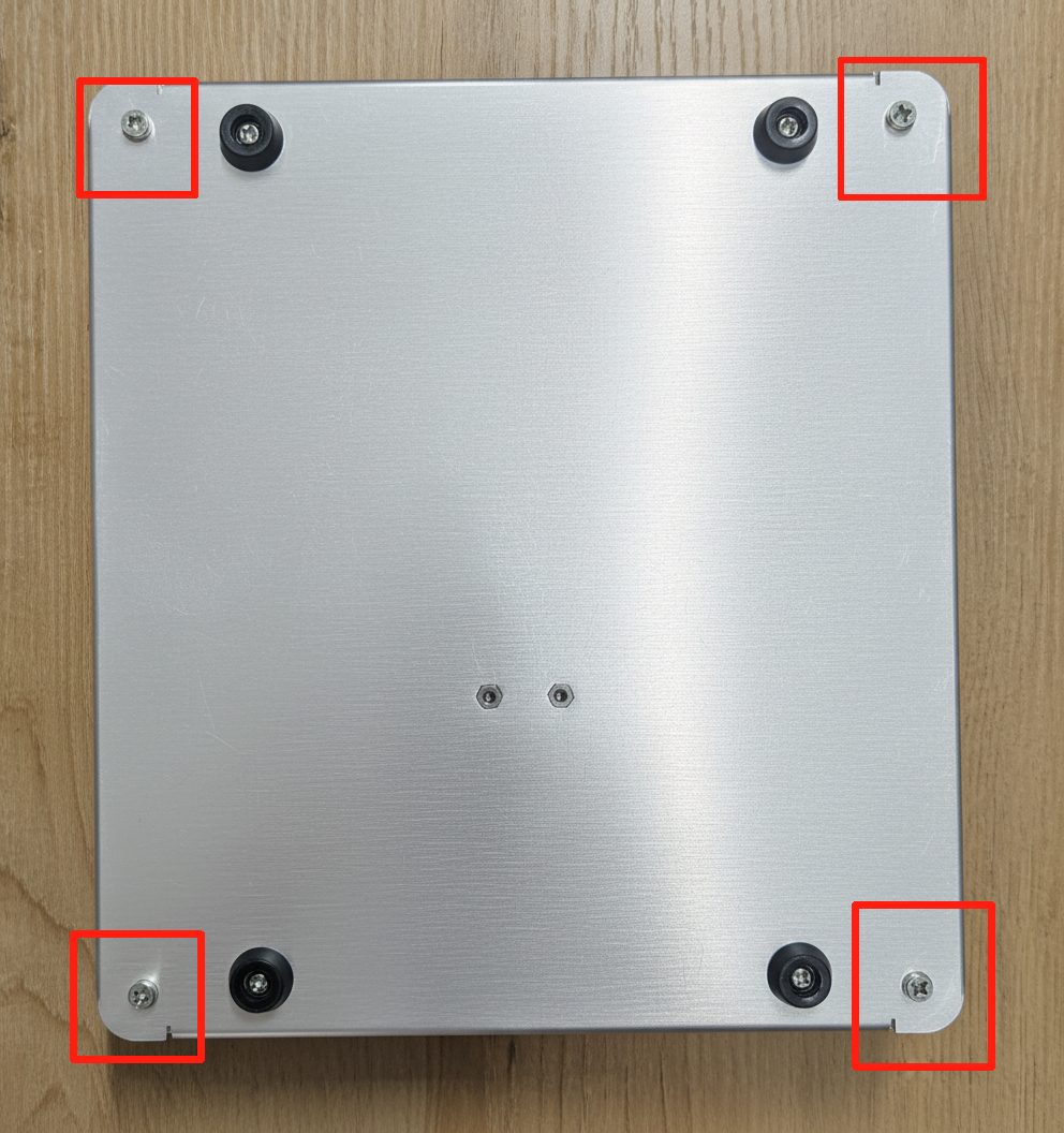
Note: Before using the interface, you must remove the housing screws and install the corresponding module as shown in the figure below.
Usage Instruction
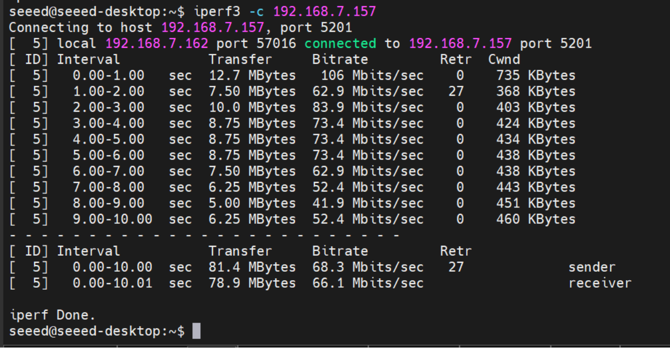
Performance Test: To test Wi-Fi performance, use the following command (replace the IP address with your test server):
# On server: iperf3 -s
# On client:
iperf3 -c 192.168.7.157
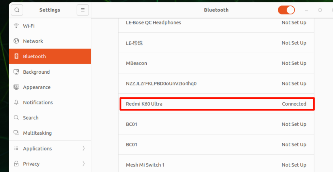
Bluetooth functionality is available via the M.2 Key E slot. Bluetooth Testing:
M.2 Key B (4G/5G Module)
The M.2 Key B slot supports 4G/5G cellular modules with Nano SIM card holder.
Hardware Connection
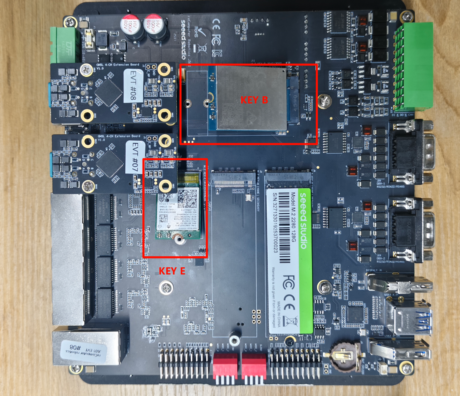
Note: Before using the interface, you must remove the housing screws and install the corresponding module as shown in the figure below.
Usage Instruction
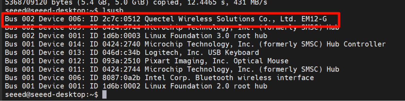
Step 1. Check Hardware Recognition
lsusb
This command displays a list of all USB devices connected to the system, along with their manufacturer (ID), type, and other information. For example, the output might show a device from Quectel Wireless Solutions Co., Ltd. EM12-G, indicating that the 5G module is present.
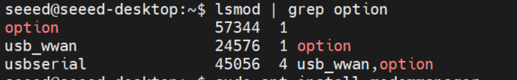
Step 2. Confirm Driver Loading It's essential to ensure that the option driver, which is required for the 5G module, is loaded. We can use the lsmod command to check.
lsmod | grep option
If the option driver is loaded successfully, relevant information about the driver will be displayed in the output.
Step 3. Configure ModemManager ModemManager is a tool for managing modem devices, and it needs to be installed and restarted.
sudo apt install modemmanager
sudo systemctl restart ModemManager
The apt install command is used to install the ModemManager package, while systemctl restart restarts the ModemManager service to ensure that the new settings take effect.
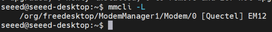
Step 4. Verify Module Identification We can use the mmcli -L command to check if the ModemManager can correctly identify the 5G module.
mmcli -L
If the 5G module is recognized, an output similar to /org/freedesktop/ModemManager1/Modem/0 will be displayed, indicating the path to the detected modem device.
Step 5. Set the APN APN (Access Point Name) is crucial for connecting a mobile device to the network.We'll use the nmcli command to create a bearer profile. Taking China Mobile as an example, we can create a configuration file with the following commands:
sudo nmcli con add type gsm ifname "*" apn "CMNET" ipv4.method auto
This command adds a new GSM (Global System for Mobile Communications) type connection, specifying the APN as "CMNET" and using automatic IPv4 configuration.
Step 6. Activate the Connection After creating the bearer profile, we need to activate the connection.
sudo nmcli con up "gsm"
This command activates the GSM connection, and if successful, a confirmation message will be displayed.

Step 7. Re-verify Module Identification Run the mmcli -L command again to ensure that the module remains recognized after configuring the APN.
mmcli -L
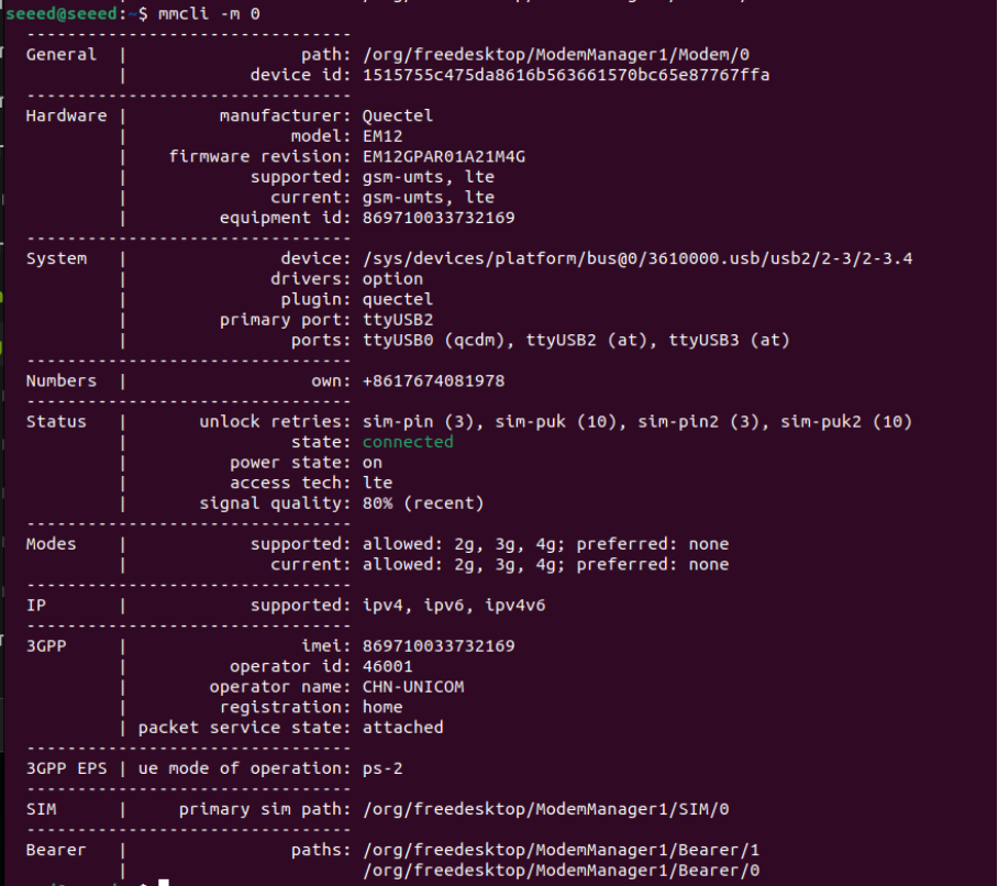
Step 8. Check Module Status Finally, we can use the mmcli -m 0 command to view detailed information about the module, such as IP allocation, carrier, and network connection status.
mmcli -m 0
This command provides comprehensive details about the 5G module, including its manufacturer, model, supported and current network technologies, device status, and connected network operators.
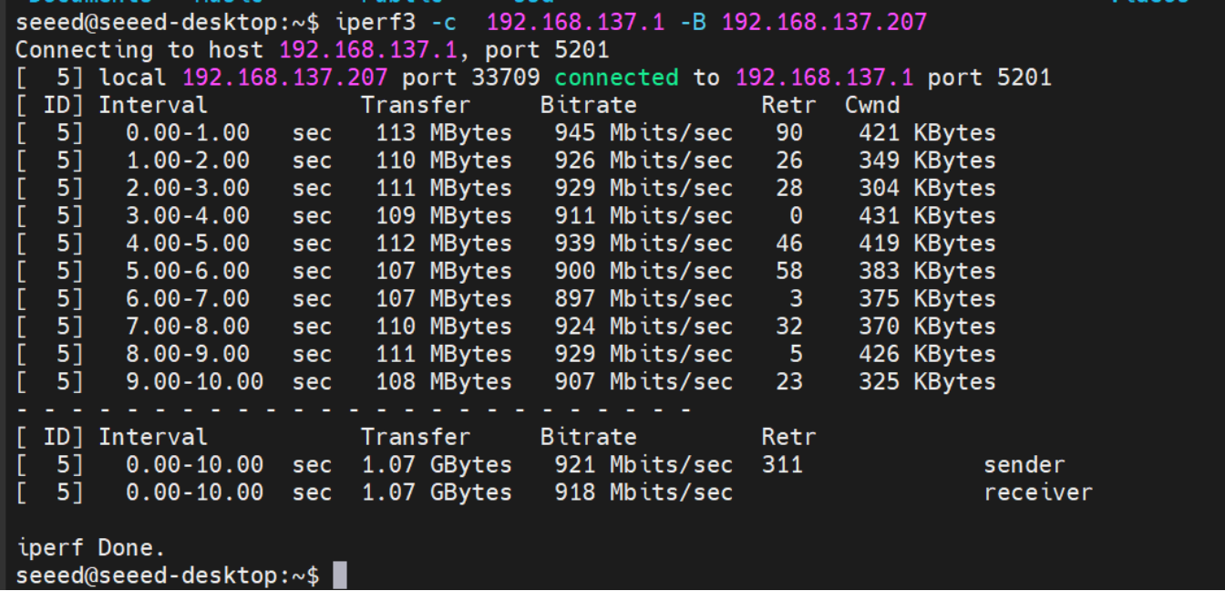
Ethernet
The Robotics J501 provides 1x 10GbE (native) and 4x 1GbE (via PCIe switch) RJ45 ports. The 10GbE port features TI TQSPH-10G PHY, supporting five speeds: 10/5/2.5/1/0.1 GbE. The 1GbE ports support 10/100/1000M speeds.
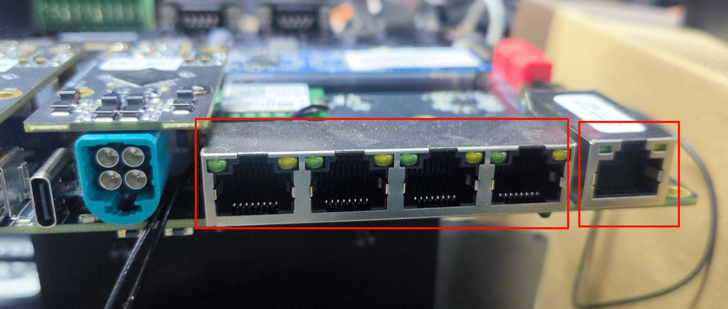
LED Indicators per port:
- Green LED: ON for 10G/5G/2.5G/1000M link
- Yellow LED: Blinks for network activity
To test Ethernet port speed, use iperf3 as follows :
iperf3 -c <server_ip> -B <bind_ip>
<server_ip> is the IP address of the iperf3 server. The client will connect to this server to perform a bandwidth test.
<bind_ip> binds the specified local IP address as the source of the test traffic.
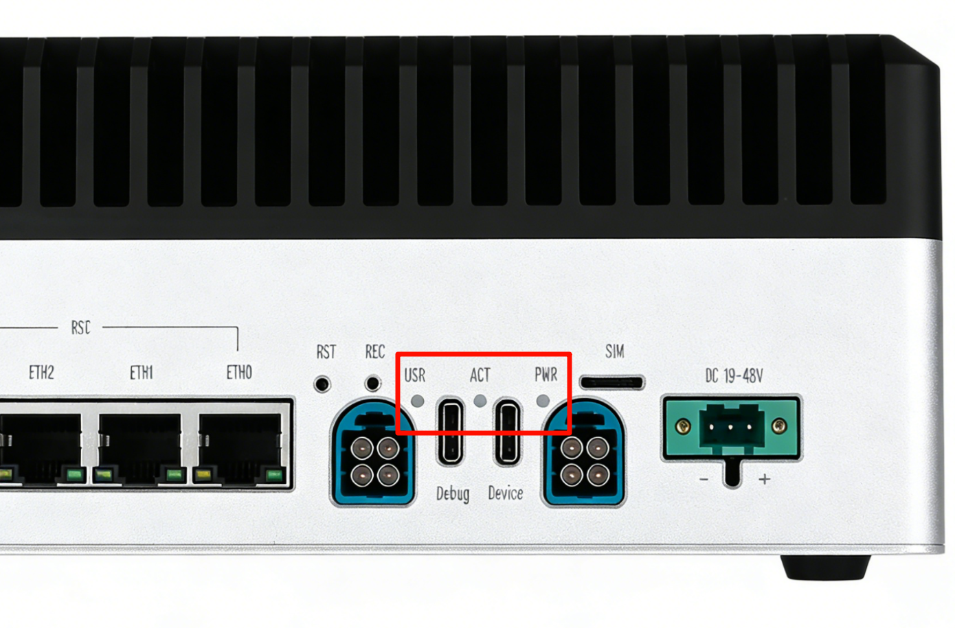
LED
The J501 features multiple status LEDs:
- PWR LED: Power status (green)
- ACT LED: System activity (yellow)
- USR LED: Via GPIO control
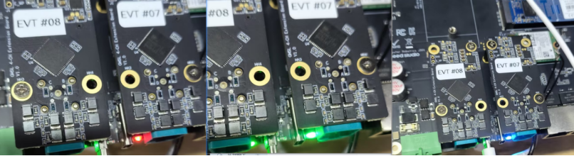
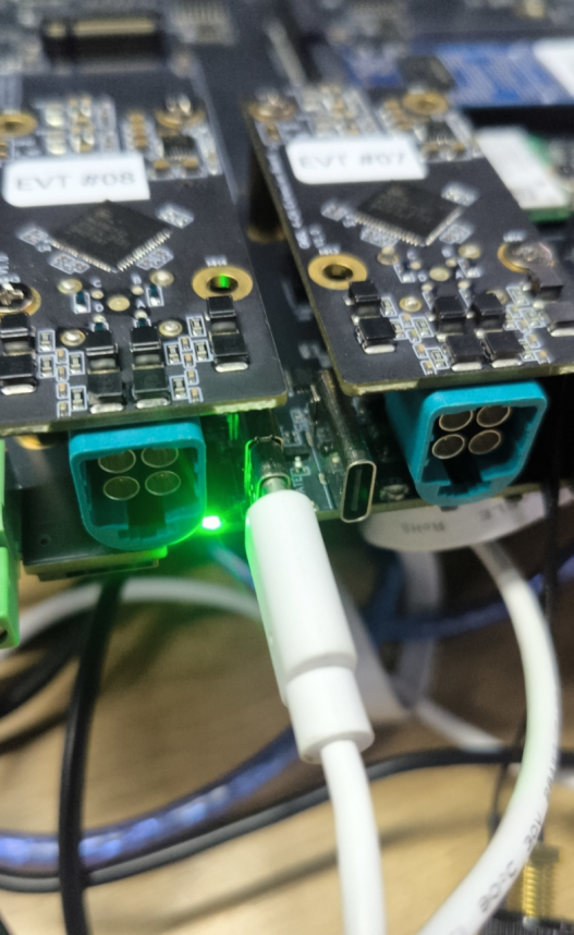
Usage Instruction
The following demonstrates how to control the USER LEDs to be green, red, or blue.
#change to red
echo 1 | sudo tee /sys/class/leds/on-board:red/brightness
echo 0 | sudo tee /sys/class/leds/on-board:red/brightness
#change to green
echo 1 | sudo tee /sys/class/leds/on-board:green/brightness
echo 0 | sudo tee /sys/class/leds/on-board:green/brightness

#change to blue
echo 1 | sudo tee /sys/class/leds/on-board:blue/brightness
echo 0 | sudo tee /sys/class/leds/on-board:blue/brightness
The LED control effect is shown in the figure below:
USB
The Robotics J501 provides 4x USB 3.2 Type-A ports (via an internal USB 3.1 Gen1 hub, supporting up to 5Gbps data rates for connecting high-speed peripherals, storage devices, or cameras) and 1x USB 2.0 Type-C debug port (which functions as a serial console for accessing system logs, debugging boot issues, and performing firmware updates).
USB-A Speed Test
Create a script to test USB device speed:
vim test_usb.sh
Paste the following content:
test_usb.sh
cat <<'EOF' | sudo tee test_usb.sh >/dev/null
#!/bin/bash
set -e

MOUNT_POINT="$1"
TEST_FILE="$MOUNT_POINT/test_usb_speed.bin"

if [ -z "$MOUNT_POINT" ]; then
  echo "Usage: $0 <mount_point>"
  echo "Example: $0 /media/seeed/USB"
  exit 1
fi

if [ ! -d "$MOUNT_POINT" ]; then
  echo "Error: $MOUNT_POINT is not a directory"
  exit 1
fi

echo "Write test..."
dd if=/dev/zero of="$TEST_FILE" bs=1M count=2048 conv=fdatasync status=progress

echo
echo "Drop caches..."
sync
echo 3 | sudo tee /proc/sys/vm/drop_caches >/dev/null

echo "Read test..."
dd if="$TEST_FILE" of=/dev/null bs=1M count=2048 status=progress

echo
echo "Cleaning up..."
rm -f "$TEST_FILE"
EOF
Make the script executable and test:
sudo chmod +x test_usb.sh
./test_usb.sh /mnt          # If your USB drive is mounted at /mnt
# Or
./test_usb.sh /media/usb    # If your USB drive is mounted at /media/usb
# Or
./test_usb.sh /path/to/your/usb/mount_point

Please confirm the actual mount point of your USB device first using the df -h or lsblk command!
USB 2.0 Type-C port
Using this serial port, via the USB-C data cable, you can monitor the debugging information of input and output on the PC side.
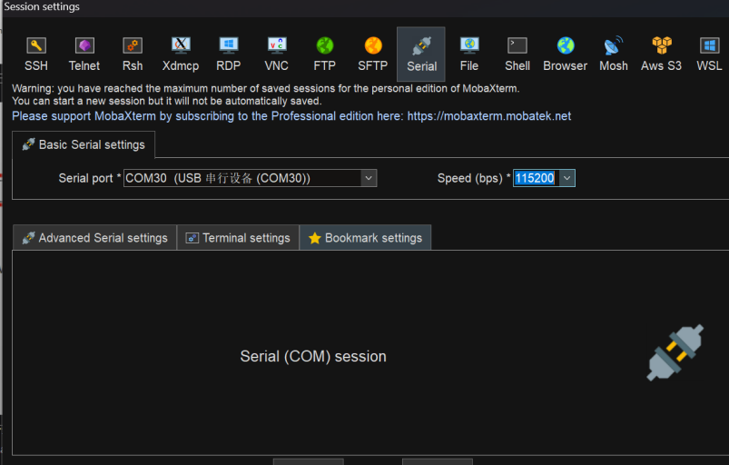
Step 1. Open the serial port tool(Here, we use the MobaXterm tool as an example), create a new session.

Step 2. Select the Serial tool.

Step 3. Select corresponding serial port, set the baud rate to 115200 and click "OK".
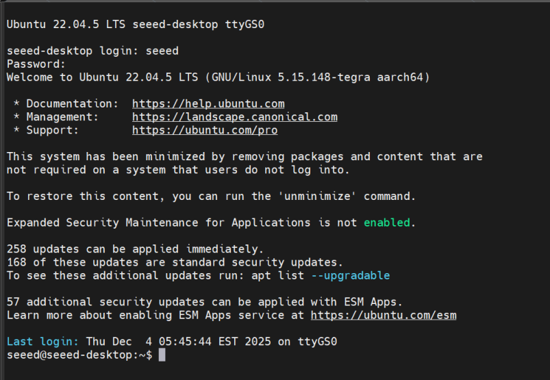
Step 4. Login your reComputer Super with the username and password.
Fan
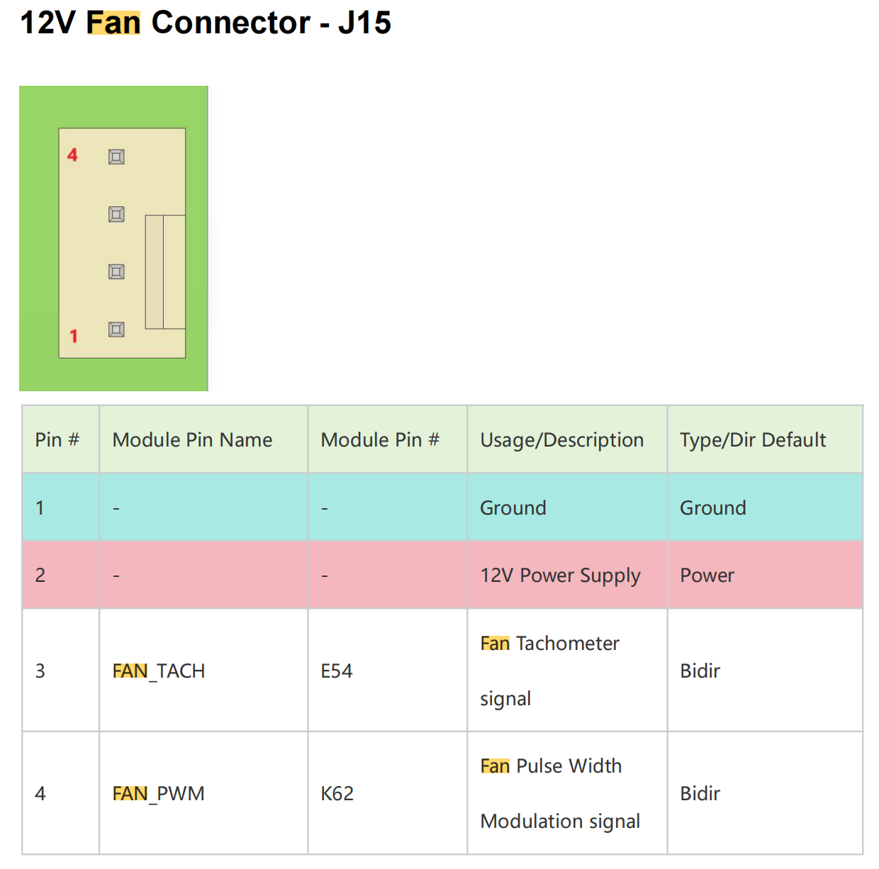
The Robotics J501 provides two 4-pin PWM fan connectors designed to cool both the Jetson module and carrier board components:
- 12V Fan: 2.54 mm connector, max 1.5A, suitable for high-performance cooling
- 5V Fan: 1.25 mm JST connector, max 1.5A, ideal for low-power silent cooling
The PWM control allows for dynamic and precise speed adjustment based on system temperature, enabling efficient cooling while minimizing noise and power consumption.
12V Fan Pinout:
The 12V fan connector (2.54 mm) has the following pinout:
Usage Instruction
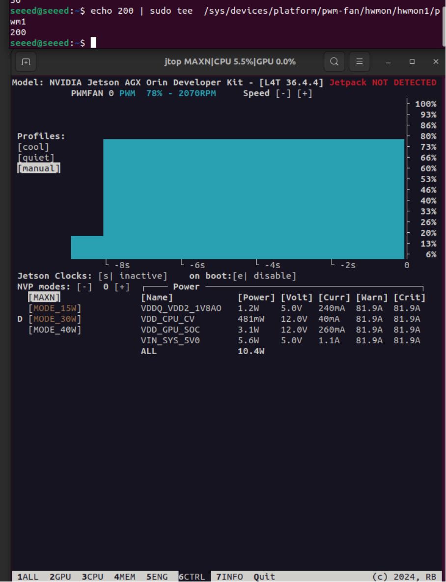
Manual PWM Control:
# Set fan speed (0-255)
sudo -i
echo 200 > /sys/bus/platform/devices/pwm-fan/hwmon/hwmon1/pwm1
Default thermal policy is pre-configured in /etc/nvpmodel.conf. For custom profiles, refer to NVIDIA Jetson Linux Developer Guide.
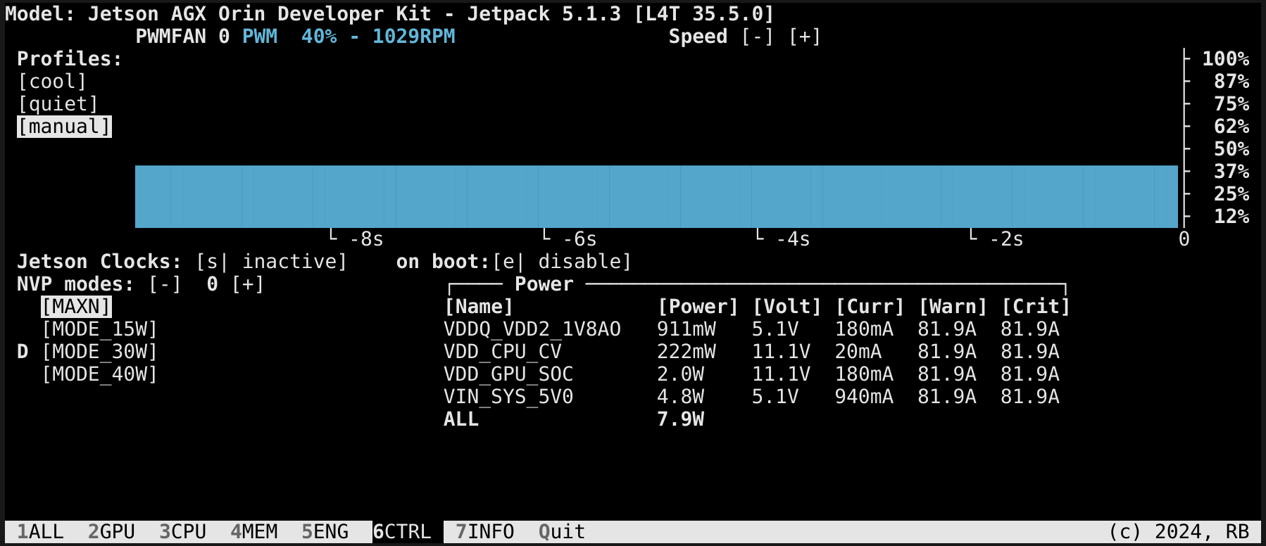
Additionally, we can manually set the fan speed using the jtop tool.
You can enter the following command in the terminal to install jtop.
sudo apt update
sudo apt install python3-pip -y
sudo pip3 install jetson-stats
Then reboot your reComputer Mini:
sudo reboot
After installing jtop, you can lanch it in terminal:
jtop
CAN
The reComputer Robotics J501 is equipped with 4 independent CAN interfaces (CAN 0, CAN 1, CAN 2, CAN 3), which share the J25 2x10P connector with DI/DO interfaces. These interfaces support both Classic CAN and CAN FD communication protocols, featuring high anti-interference performance and real-time data transmission, making them suitable for industrial control scenarios such as automotive electronics, industrial automation, and robotics.
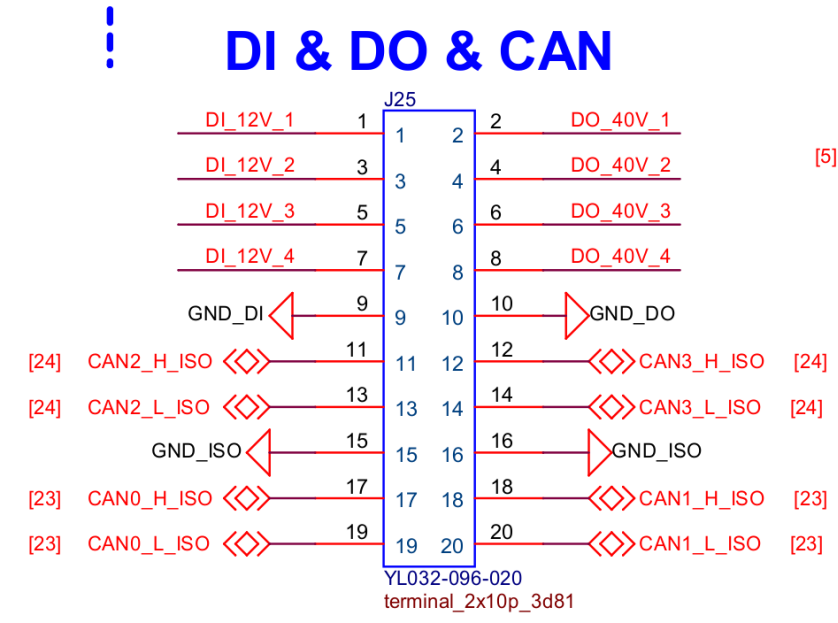
Usage Instruction
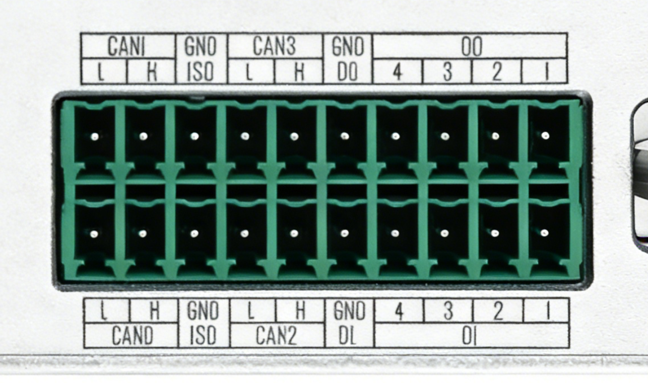
This is the schematic diagram of the CAN interface.
CAN Communication
This section demonstrates connecting CAN0↔CAN1 and CAN2↔CAN3 on the Jetson and shows how to send and receive data between those pairs in both Classic CAN mode and CAN‑FD mode.
| Channel Name | Interface Type | Pin Name | GPIO Chip | GPIO Number | Termination Resistor Control |
|---|---|---|---|---|---|
| CAN0 | Native | PAA.04 | gpiochip1 | 4 | gpiochip1 line4 (PAA.04) |
| CAN1 | Native | PAA.07 | gpiochip1 | 7 | gpiochip1 line7 (PAA.07) |
| CAN2 | SPI-to-CAN | - | gpiochip2 | 10 | gpiochip2 line10 |
| CAN3 | SPI-to-CAN | - | gpiochip2 | 12 | gpiochip2 line12 |
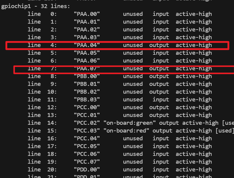
The termination resistors for CAN0 and CAN1 can be controlled via two pins: PAA.04, located at gpiochip1 line4, and PAA.07, located at gpiochip1 line7.
Termination resistor control follows these rules:
When `PAA.04 = 1`, the 120 Ω termination resistor of CAN0 is **disconnected**;
when `PAA.04 = 0`, the 120 Ω termination resistor of CAN0 is **connected**.

When `PAA.07 = 1`, the 120 Ω termination resistor of CAN1 is **disconnected**;
when `PAA.07 = 0`, the 120 Ω termination resistor of CAN1 is **connected**.
Enter the following command to view the pins on gpiochip 1:
gpioinfo gpiochip1
Refer to the following commands to set PAA.04 and PAA.07 to 0:
sudo gpioset --mode=wait gpiochip1 4=0
sudo gpioset --mode=wait gpiochip1 7=0
Refer to the following commands to set PAA.04 and PAA.07 to 1:
sudo gpioset --mode=wait gpiochip1 4=1
sudo gpioset --mode=wait gpiochip1 7=1
Classic CAN mode
The following script implements loopback communication testing between CAN0/CAN1 and CAN2/CAN3, including enabling the terminal resistor, configuring the bitrate, and bidirectional data transmission.
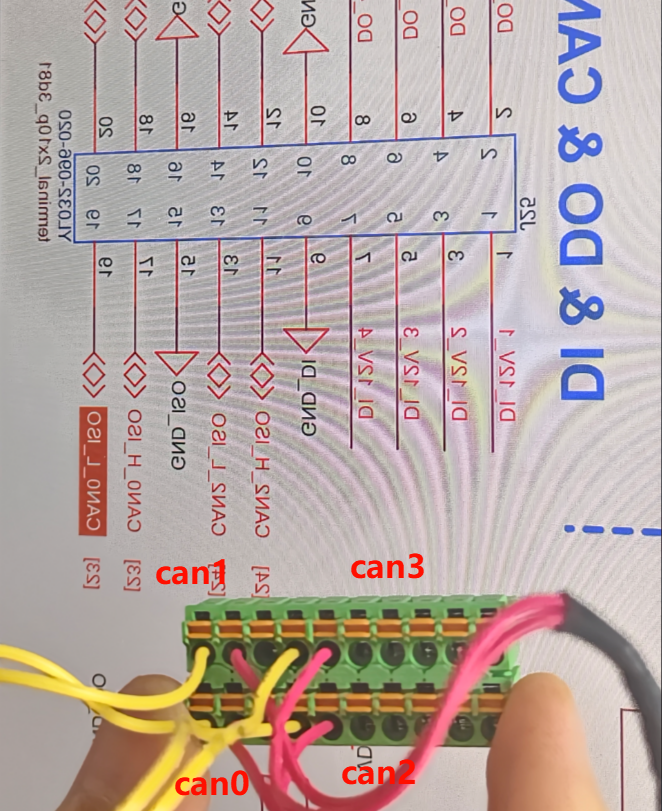
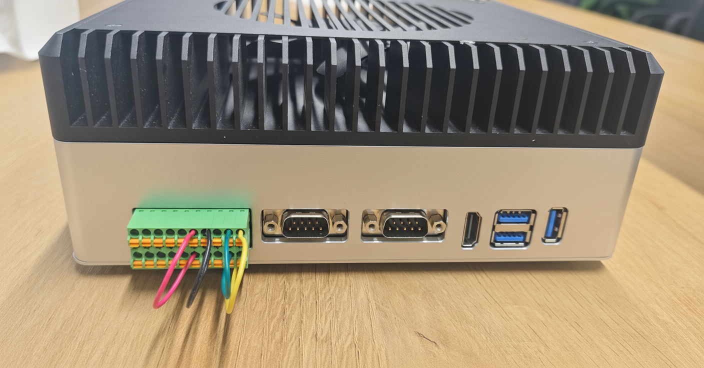
The wiring diagram is shown below:
| From | To |
|---|---|
| CAN0_H | CAN1_H |
| CAN0_L | CAN1_L |
| CAN2_H | CAN3_H |
| CAN2_L | CAN3_L |
The wiring diagram is shown below:
Create test_can.sh to test data transmission and reception between CAN0↔CAN1 and CAN2↔CAN3 in standard mode:
touch test_can.sh
sudo chmod +x test_can.sh
sudo ./test_can.sh
The script code for test_can.sh is as follows:
test_can.sh
#!/bin/bash
set -e

PW="000000"

echo "$PW" | sudo -S ip link set can0 down || true
echo "$PW" | sudo -S ip link set can1 down || true
echo "$PW" | sudo -S ip link set can2 down || true
echo "$PW" | sudo -S ip link set can3 down || true

# Set socket buffer sizes
echo "$PW" | sudo -S sysctl -w net.core.rmem_max=524288
echo "$PW" | sudo -S sysctl -w net.core.wmem_max=524288
echo "$PW" | sudo -S sysctl -w net.core.rmem_default=524288
echo "$PW" | sudo -S sysctl -w net.core.wmem_default=524288

# Set bitrate, 1 Mbps
BITRATE=1000000
echo "$PW" | sudo -S ip link set can0 type can bitrate ${BITRATE}
echo "$PW" | sudo -S ip link set can1 type can bitrate ${BITRATE}
echo "$PW" | sudo -S ip link set can0 up
echo "$PW" | sudo -S ip link set can1 up

echo "$PW" | sudo -S ip link set can2 type can bitrate ${BITRATE}
echo "$PW" | sudo -S ip link set can3 type can bitrate ${BITRATE}
echo "$PW" | sudo -S ip link set can2 up
echo "$PW" | sudo -S ip link set can3 up

sleep 1

# Enable termination resistors
sudo pkill -f gpioset || true
gpioset --mode=time --sec=200000 gpiochip2 8=0 & # enable CAN1 120R
GPIO1_PID=$!
gpioset --mode=time --sec=200000 gpiochip2 9=0 & # enable CAN0 120R
GPIO2_PID=$!
gpioset --mode=time --sec=200000 gpiochip2 12=0 & # enable CAN3 120R
GPIO3_PID=$!
gpioset --mode=time --sec=200000 gpiochip2 10=0 & # enable CAN2 120R
GPIO4_PID=$!

echo "Start candump on can0 & can1..."
candump can0 &
DUMP0_PID=$!
candump can1 &
DUMP1_PID=$!

echo "Start candump on can2 & can3..."
candump can2 &
DUMP2_PID=$!
candump can3 &
DUMP3_PID=$!

echo "Start cangen on can0 & can1 and can2 & can3 (bi-directional test)..."
# -g 10 sends one frame every 10 ms; adjust as needed
cangen can0 -g 10 &
GEN0_PID=$!
cangen can1 -g 10 &
GEN1_PID=$!
cangen can2 -g 10 &
GEN2_PID=$!
cangen can3 -g 10 &
GEN3_PID=$!

# Cleanup background processes on Ctrl+C
cleanup() {
  echo
  echo "Stopping CAN test..."
  kill $GEN0_PID $GEN1_PID $DUMP0_PID $DUMP1_PID $GPIO1_PID $GPIO2_PID 2>/dev/null || true
  kill $GEN2_PID $GEN3_PID $DUMP2_PID $DUMP3_PID $GPIO3_PID $GPIO4_PID 2>/dev/null || true
  echo "$PW" | sudo -S ip link set can0 down || true
  echo "$PW" | sudo -S ip link set can1 down || true
  echo "$PW" | sudo -S ip link set can2 down || true
  echo "$PW" | sudo -S ip link set can3 down || true
  echo "Done."
}
trap cleanup INT TERM

# Wait for child processes (candump runs until you Ctrl+C)
wait
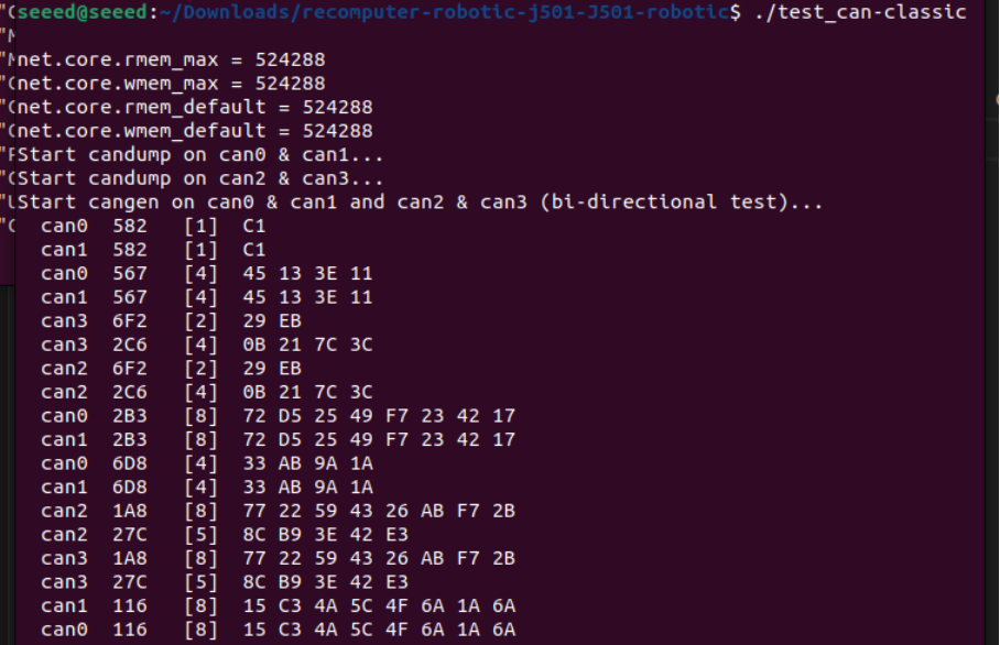
In the CAN test script, replace PW with your own Jetson password.
Data transmission and reception between CAN0 and CAN1 will be completed:
CAN-FD mode
CAN FD supports higher data transmission rates and larger data frame lengths. The following script implements CAN FD loopback testing.
Create test_canfd.sh to test data transmission and reception between CAN0↔CAN1 and CAN2↔CAN3 in CAN-FD mode:
touch test_canfd.sh
sudo chmod +x test_canfd.sh
sudo ./test_canfd.sh
The script code for test_canfd.sh is as follows:
test_canfd.sh
#!/bin/bash
set -e

PW="000000"

echo "$PW" | sudo -S ip link set can0 down || true
echo "$PW" | sudo -S ip link set can1 down || true
echo "$PW" | sudo -S ip link set can2 down || true
echo "$PW" | sudo -S ip link set can3 down || true

# Set socket buffers
echo "$PW" | sudo -S sysctl -w net.core.rmem_max=524288
echo "$PW" | sudo -S sysctl -w net.core.wmem_max=524288
echo "$PW" | sudo -S sysctl -w net.core.rmem_default=524288
echo "$PW" | sudo -S sysctl -w net.core.wmem_default=524288

# ---- CAN-FD parameters ----
BITRATE=500000        # Arbitration (nominal) bitrate
DBITRATE=5000000      # Data phase bitrate (FD fast mode)

# Configure CAN-FD: arbitration bitrate + data bitrate + FD on + error reporting + auto restart
echo "$PW" | sudo -S ip link set can0 type can bitrate $BITRATE dbitrate $DBITRATE fd on berr-reporting on restart-ms 100
echo "$PW" | sudo -S ip link set can1 type can bitrate $BITRATE dbitrate $DBITRATE fd on berr-reporting on restart-ms 100
echo "$PW" | sudo -S ip link set can2 type can bitrate $BITRATE dbitrate $DBITRATE fd on berr-reporting on restart-ms 100
echo "$PW" | sudo -S ip link set can3 type can bitrate $BITRATE dbitrate $DBITRATE fd on berr-reporting on restart-ms 100

echo "$PW" | sudo -S ip link set can0 up
echo "$PW" | sudo -S ip link set can1 up
echo "$PW" | sudo -S ip link set can2 up
echo "$PW" | sudo -S ip link set can3 up

sleep 1

# Enable termination resistors
sudo pkill -f gpioset || true
gpioset --mode=time --sec=200000 gpiochip2 8=0 &   # enable CAN1 120R
GPIO1_PID=$!
gpioset --mode=time --sec=200000 gpiochip2 9=0 &   # enable CAN0 120R
GPIO2_PID=$!
gpioset --mode=time --sec=200000 gpiochip2 12=0 &  # enable CAN3 120R
GPIO3_PID=$!
gpioset --mode=time --sec=200000 gpiochip2 10=0 &  # enable CAN2 120R
GPIO4_PID=$!

echo "Start candump on can0 & can1..."
candump can0 &
DUMP0_PID=$!
candump can1 &
DUMP1_PID=$!

echo "Start candump on can2 & can3..."
candump can2 &
DUMP2_PID=$!
candump can3 &
DUMP3_PID=$!

echo "Start cangen on can0 & can1 and can2 & can3 (bi-directional test)..."
# -g 10 sends one frame every 10 ms; adjust as needed
cangen can0 -g 10 &
GEN0_PID=$!
cangen can1 -g 10 &
GEN1_PID=$!
cangen can2 -g 10 &
GEN2_PID=$!
cangen can3 -g 10 &
GEN3_PID=$!

# Cleanup background processes on Ctrl+C
cleanup() {
  echo
  echo "Stopping CAN-FD test..."
  kill $GEN0_PID $GEN1_PID $DUMP0_PID $DUMP1_PID $GPIO1_PID $GPIO2_PID 2>/dev/null || true
  kill $GEN2_PID $GEN3_PID $DUMP2_PID $DUMP3_PID $GPIO3_PID $GPIO4_PID 2>/dev/null || true
  echo "$PW" | sudo -S ip link set can0 down || true
  echo "$PW" | sudo -S ip link set can1 down || true
  echo "$PW" | sudo -S ip link set can2 down || true
  echo "$PW" | sudo -S ip link set can3 down || true
  echo "Done."
}
trap cleanup INT TERM

# Wait for child processes (candump will run until you Ctrl+C)
wait
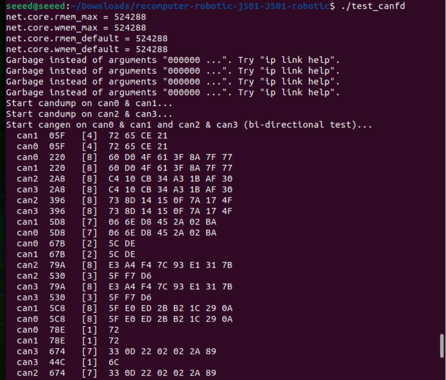
In the CAN test script, replace PW with your own Jetson password.
Data transmission and reception between CAN0↔CAN1 and CAN2↔CAN3 will be completed:
DI/DO
The DI/DO interfaces of reComputer Robotics J501 are integrated on the J25 2x10P connector, sharing the interface with CAN interfaces. They support 4-channel digital input and 4-channel digital output, featuring stable signal transmission and industrial-grade voltage adaptation, suitable for connecting digital sensors, relays, and other peripheral devices.
Hardware Connection
Digital Input (DI) Channels
| Channel Name | Voltage Characteristics | GPIO Label | Pin Name | GPIO Chip | GPIO Number |
|---|---|---|---|---|---|
| DI_12V_1 | 12V input adaptive | DI_1_GPIO17 | PP.04 | gpiochip0 | 96 |
| DI_12V_2 | 12V input adaptive | DI_1_GPIO18 | PQ.04 | gpiochip0 | 104 |
| DI_12V_3 | 12V input adaptive | DI_1_GPIO19 | PN.02 | gpiochip0 | 86 |
| DI_12V_4 | 12V input adaptive | DI_1_GPIO33 | PM.07 | gpiochip0 | 83 |
Digital Output (DO) Channels
| Channel Name | Voltage Characteristics | GPIO Label | Pin Name | GPIO Chip | GPIO Number | Additional Info |
|---|---|---|---|---|---|---|
| DO_40V_1 | Open-drain output; ~0V (low) when not pulled high, 12V (high) when pulled high | DO_1_GPIO | PAA.04 | gpiochip1 | 4 | Corresponding number: 320 |
| DO_40V_2 | Open-drain output; ~0V (low) when not pulled high, 12V (high) when pulled high | DO_2_GPIO | PAA.07 | gpiochip1 | 7 | Corresponding number: 323 |
| DO_40V_3 | Open-drain output; ~0V (low) when not pulled high, 12V (high) when pulled high | DO_3_GPIO | PBB.01 | gpiochip1 | 9 | Corresponding number: 325 |
| DO_40V_4 | Open-drain output; ~0V (low) when not pulled high, 12V (high) when pulled high | DO_4_GPIO | PBB.00 | gpiochip1 | 8 | Corresponding number: 324 |
The key pin definitions for DI/DO interfaces on the J25 connector are as follows (pin numbering corresponds to the physical connector):
| Pin Number | Function Label | Description |
|---|---|---|
| 1 | DI_12V_1 | 12V Digital Input Channel 1 |
| 3 | DI_12V_2 | 12V Digital Input Channel 2 |
| 5 | DI_12V_3 | 12V Digital Input Channel 3 |
| 7 | DI_12V_4 | 12V Digital Input Channel 4 |
| 9 | GND_DI | Ground for Digital Input Channels |
| 2 | DO_40V_1 | 40V Digital Output Channel 1 |
| 4 | DO_40V_2 | 40V Digital Output Channel 2 |
| 6 | DO_40V_3 | 40V Digital Output Channel 3 |
| 8 | DO_40V_4 | 40V Digital Output Channel 4 |
| 10 | GND_DO | Ground for Digital Output Channels |
For the complete pinout (including CAN interfaces), refer to the hardware documentation of reComputer Robotics J501 to avoid incorrect connections.
Usage Instruction
Digital Output (DO) Operation
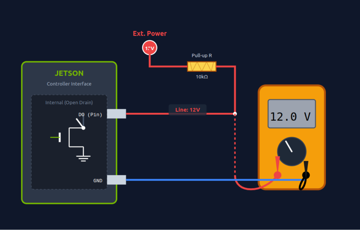
The DO interfaces adopt open-drain output. You can set the output level (high/low) via commands to control peripherals such as relays and LEDs.
Run the following command to enable the DO channel (output 12V, powered by the external pull-up resistor and 12V power supply):
# Enable DO_40V_1 (gpiochip1 4)
sudo gpioset --mode=wait 1 4=1

# Enable DO_40V_2 (gpiochip1 7)
sudo gpioset --mode=wait 1 7=1

# Enable DO_40V_3 (gpiochip1 9)
sudo gpioset --mode=wait 1 9=1

# Enable DO_40V_4 (gpiochip1 8)
sudo gpioset --mode=wait 1 8=1
DO Before Pulling High:
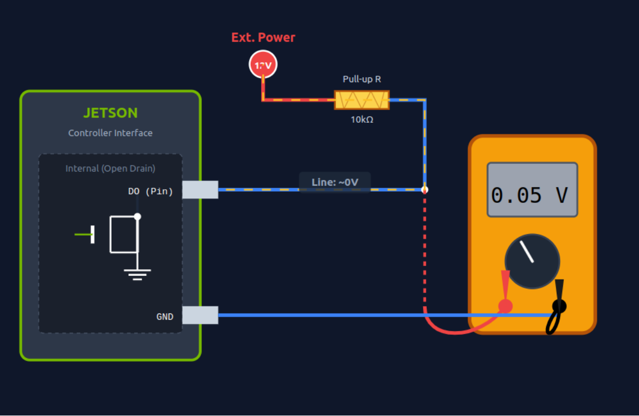
DO After Pulling High:
Run the following command to disable the DO channel (output ~0V):
# Disable DO_40V_1 (gpiochip1 4)
sudo gpioset --mode=wait 1 4=0

# Disable DO_40V_2 (gpiochip1 7)
sudo gpioset --mode=wait 1 7=0

# Disable DO_40V_3 (gpiochip1 9)
sudo gpioset --mode=wait 1 9=0

# Disable DO_40V_4 (gpiochip1 8)
sudo gpioset --mode=wait 1 8=0
Digital Input (DI) Operation
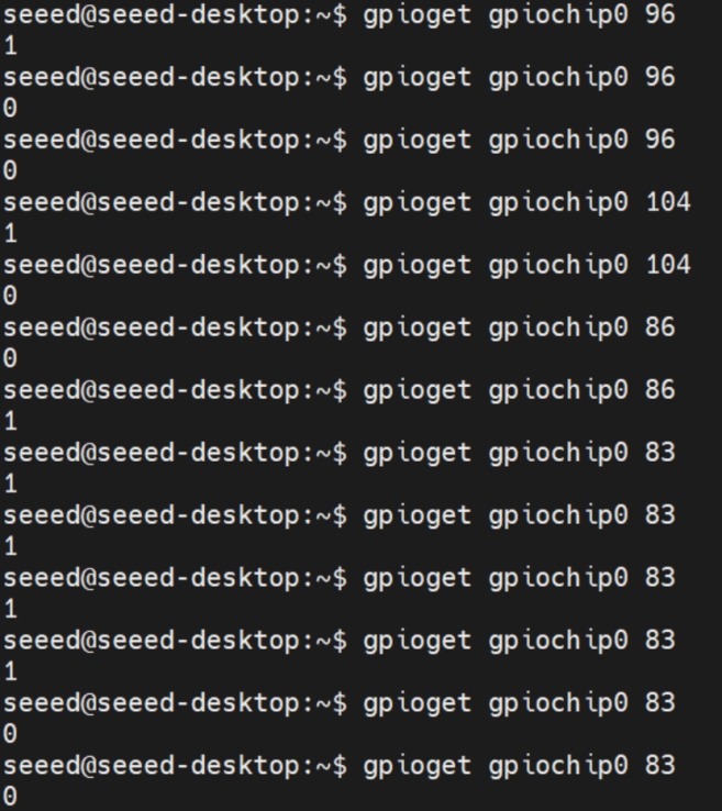
Use the gpioget command to read the input level of the DI channel (return value 1 = high level, 0 = low level) and obtain the status of peripheral devices.
The command to read the DI Channel Level is as follows:
# Read DI_12V_1 (gpiochip0 96) status
gpioget gpiochip0 96

# Read DI_12V_2 (gpiochip0 104) status
gpioget gpiochip0 104

# Read DI_12V_3 (gpiochip0 86) status
gpioget gpiochip0 86

# Read DI_12V_4 (gpiochip0 83) status
gpioget gpiochip0 83
SPI
Hardware Connection
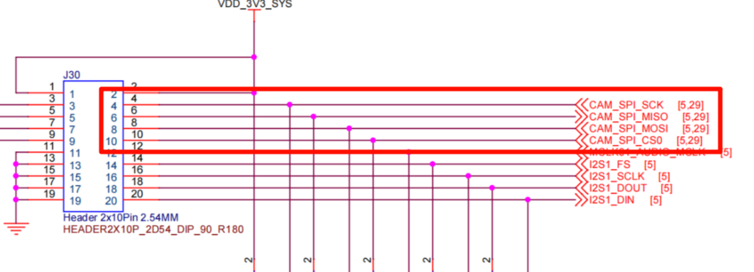
Usage Instruction
Use Dupont wires to connect the core pins of the target SPI channel (take /dev/spidev2.0 as an example): Connect the MOSI pin of SPI2.0 to its MISO pin (realize data loopback transmission/reception).
The wiring diagram is as follows:
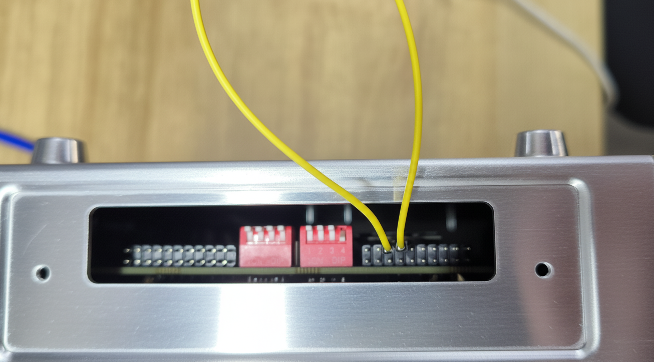
To use SPI, remove the device's side cover with a screwdriver as shown above.
Step 1: Load SPI Kernel Module (Prerequisite)
Before operating the SPI interface, ensure the spidev kernel module is loaded (the default system may preload it, but it is recommended to verify manually):
sudo modprobe spidev
If the command is executed without error prompts, it means the module is loaded successfully; if the module is already loaded, the command will not return any information, which is a normal phenomenon.
Step 2: View SPI Device Nodes Enter the following command in the terminal to view the device name mapped by the SPI interface of reComputer Robotics J501:
ls /dev/spidev*
If no device node is displayed, it means the spidev module is not loaded successfully. Re-run sudo modprobe spidev and check the system log for troubleshooting.
Step 3: Obtain and Compile the SPI Test Code
Pull the spidev-test test code from GitHub and compile it:
git clone https://github.com/rm-hull/spidev-test
cd spidev-test
gcc spidev_test.c -o spidev_test
Step 4: Run the SPI Test Program
Enter the following command in the terminal to run the SPI test program (take /dev/spidev2.0 as an example):
sudo ./spidev_test -v -D /dev/spidev2.0 -s 100000
Step 5: Verify the Test Result After running the test command, you can observe the data transmission and reception status of the SPI2.0 interface in the terminal. The core output is as follows:
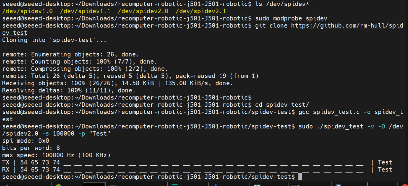
Key judgment standard: The TX (transmitted) data is consistent with the RX (received) data, indicating that the SPI loopback test is successful, and the SPI interface function is normal.
UART
The reComputer Robotics J501 is equipped with 2 independent UART interfaces (UART1 and UART2) that support RS232, RS422, and RS485 communication modes, featuring stable signal transmission and wide compatibility with peripheral devices.
Hardware Connection
UART Interface Channels
| Channel Name | Device Node | Supported Modes | Default Baud Rate | GPIO Enable Command | Mode Switch Method |
|---|---|---|---|---|---|
| UART1 (DB9-1) | /dev/ttyTHS1 | RS232, RS422, RS485 | RS232: 115200 bps; RS422/RS485: 9600 bps | gpioset --mode=wait gpiochip0 2=0 | SW3 dip switch (8-pin DIP) |
| UART2 (DB9-2) | /dev/ttyTHS4 | RS232 (default) | 115200 bps | gpioset --mode=wait gpiochip2 15=0 | Fixed RS232 (no switch) |
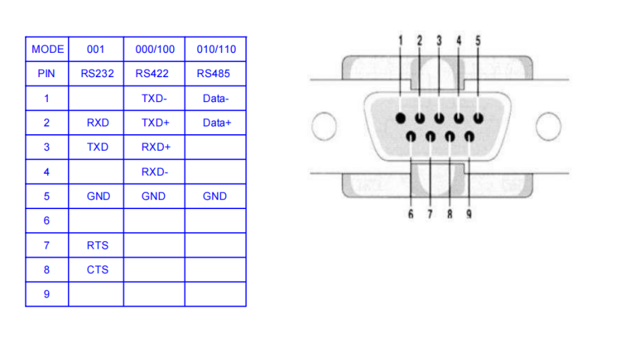
Pinout Definition (DB9 Connector)
The function of each DB9 pin varies by communication mode. Refer to the table below for accurate wiring (pin numbering follows standard DB9 male connector specifications):
| DB9 Pin Number | RS232 Mode Function | RS422 Mode Function | RS485 Mode Function |
|---|---|---|---|
| 1 | - | TXD- (Transmit Data-) | Data- (Differential Data-) |
| 2 | RXD (Receive Data) | TXD+ (Transmit Data+) | Data+ (Differential Data+) |
| 3 | TXD (Transmit Data) | RXD+ (Receive Data+) | - |
| 4 | - | RXD- (Receive Data-) | - |
| 5 | GND (Ground) | GND (Ground) | GND (Ground) |
| 6 | - | - | - |
| 7 | RTS (Request to Send) | - | - |
| 8 | CTS (Clear to Send) | - | - |
| 9 | - | - | - |
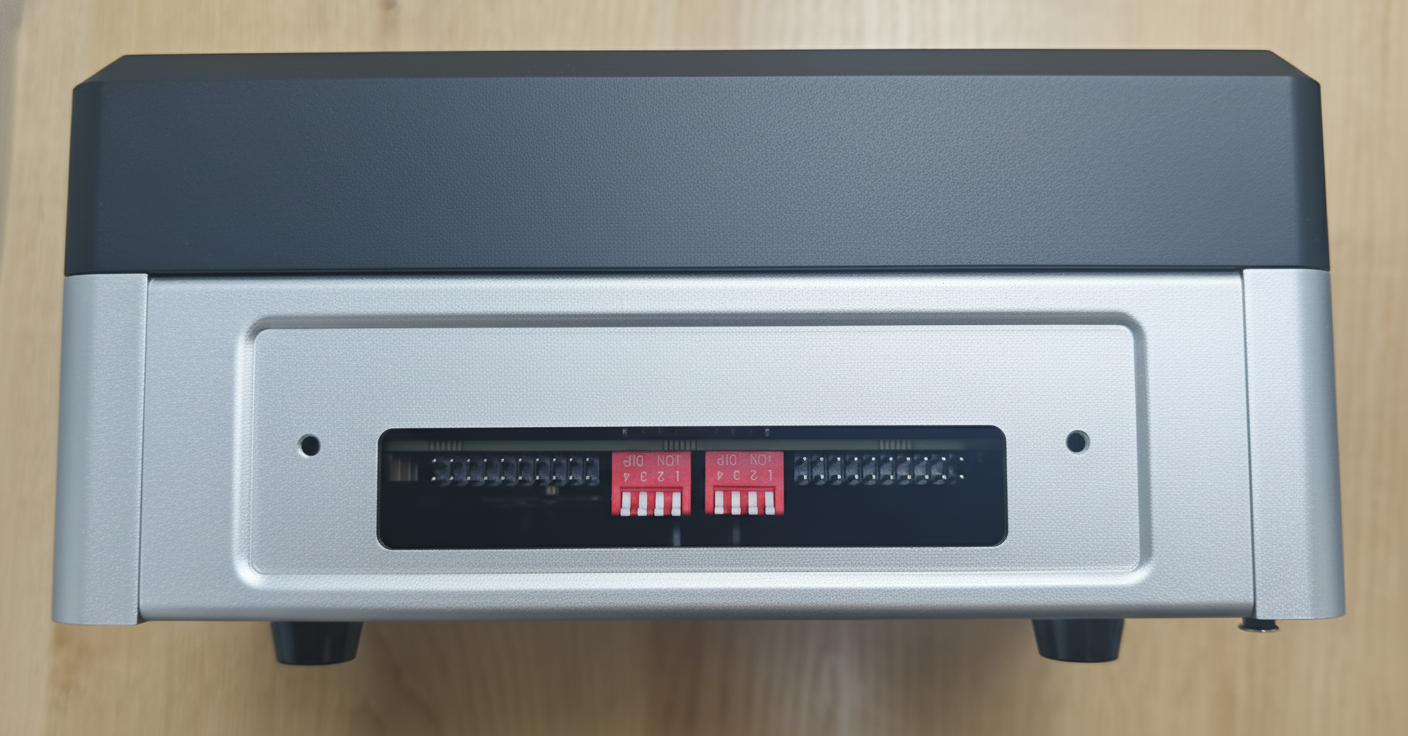
Mode Configuration (SW3 Dip Switch)
Only UART1 (DB9-1) supports mode switching via the SW3 dip switch (UART2 is fixed to RS232). The switch is an 8-pin DIP type, with core configuration pins labeled MODE_0, MODE_1, and MODE_2 in the schematic.
The interface is shown in the figure below:
Configuration Rules
| Working Mode | Dip Switch Combination (MODE_2, MODE_1, MODE_0) | Switch State Operation |
|---|---|---|
| RS232 | 0 (OFF), 0 (OFF), 1 (ON) | MODE_0: Toggle to ON; MODE_1/MODE_2: Keep OFF |
| RS422 | 0 (OFF), 0 (OFF), 0 (OFF) or 1 (ON), 0 (OFF), 0 (OFF) | MODE_0/MODE_1: Keep OFF; MODE_2: Optional (ON/OFF) |
| RS485 | 0 (OFF), 1 (ON), 0 (OFF) or 1 (ON), 1 (ON), 0 (OFF) | MODE_1: Toggle to ON; MODE_0/MODE_2: Optional (ON/OFF) |
After completing hardware connection, use terminal software (e.g., CuteCom) to test UART communication function. If CuteCom is not installed, run sudo apt-get install cutecom to install it. Ensure that the UART channel has been enabled through the GPIO command.
Usage Instruction
GPIO Enable Commands
Before connecting, execute the GPIO enable command in the terminal to activate the corresponding UART channel:
# Enable UART1 (ttyTHS1)
sudo gpioset --mode=wait gpiochip0 2=0

# Enable UART2 (ttyTHS4)
sudo gpioset --mode=wait gpiochip2 15=0
RS232 Mode Test
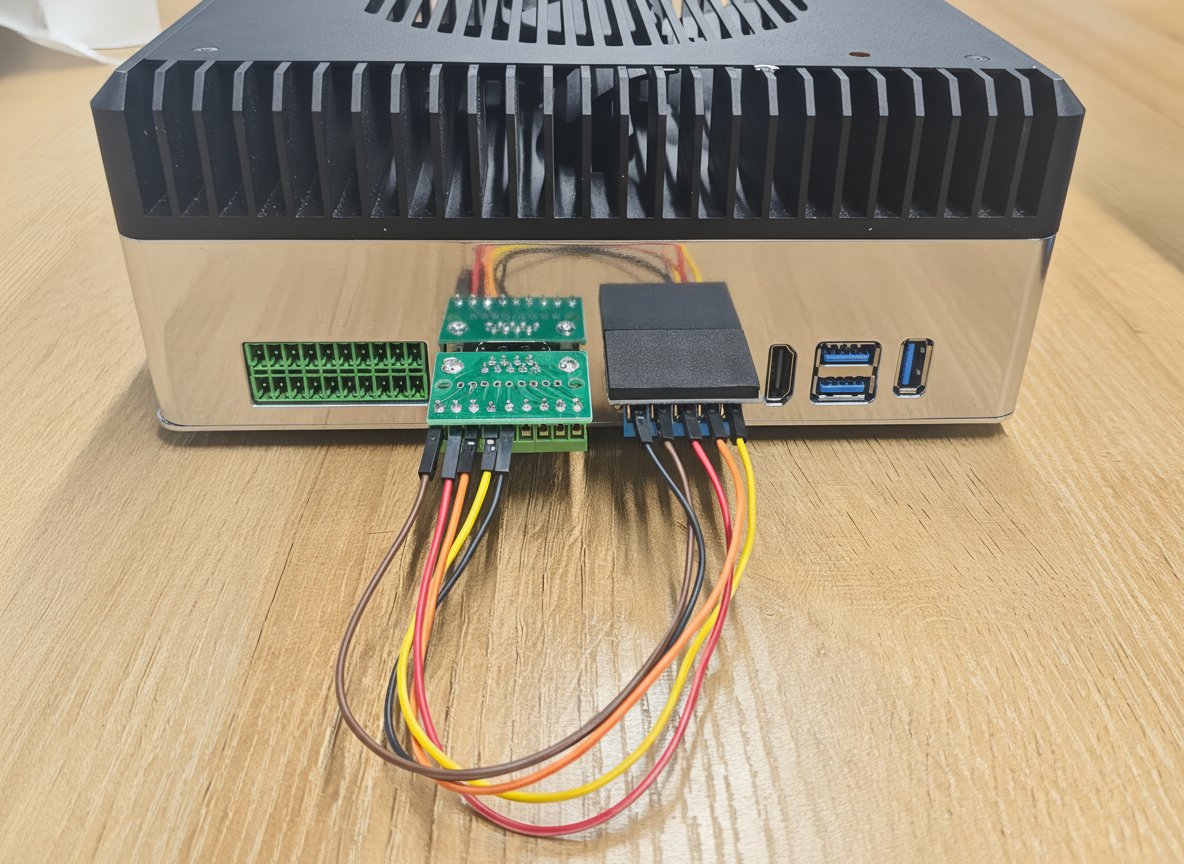
Here you can use a USB to RS232 adapter to test the interface. We have used UGREEN USB to RS232 Adapter for our testing.
The wiring diagram is shown below:
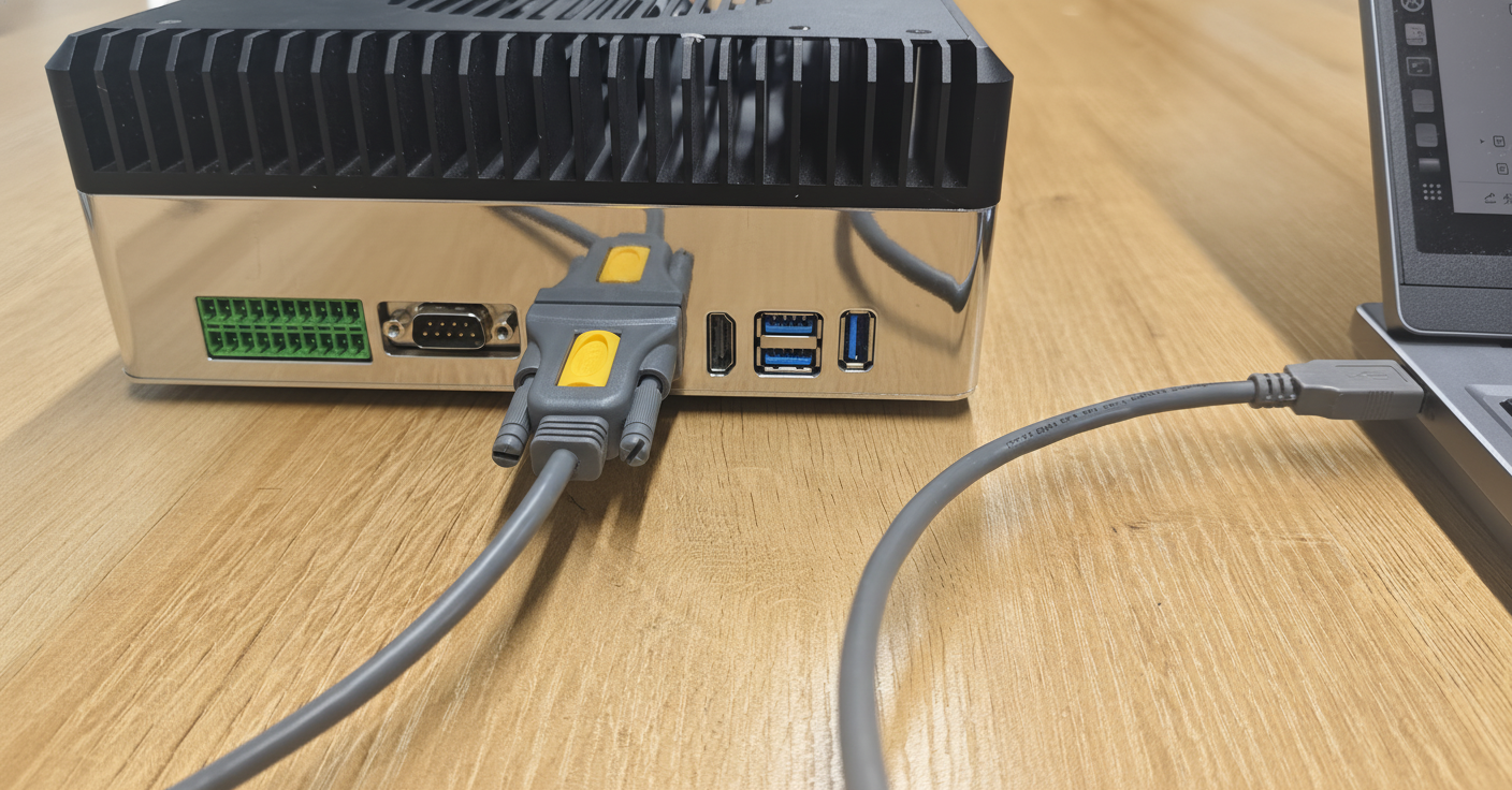
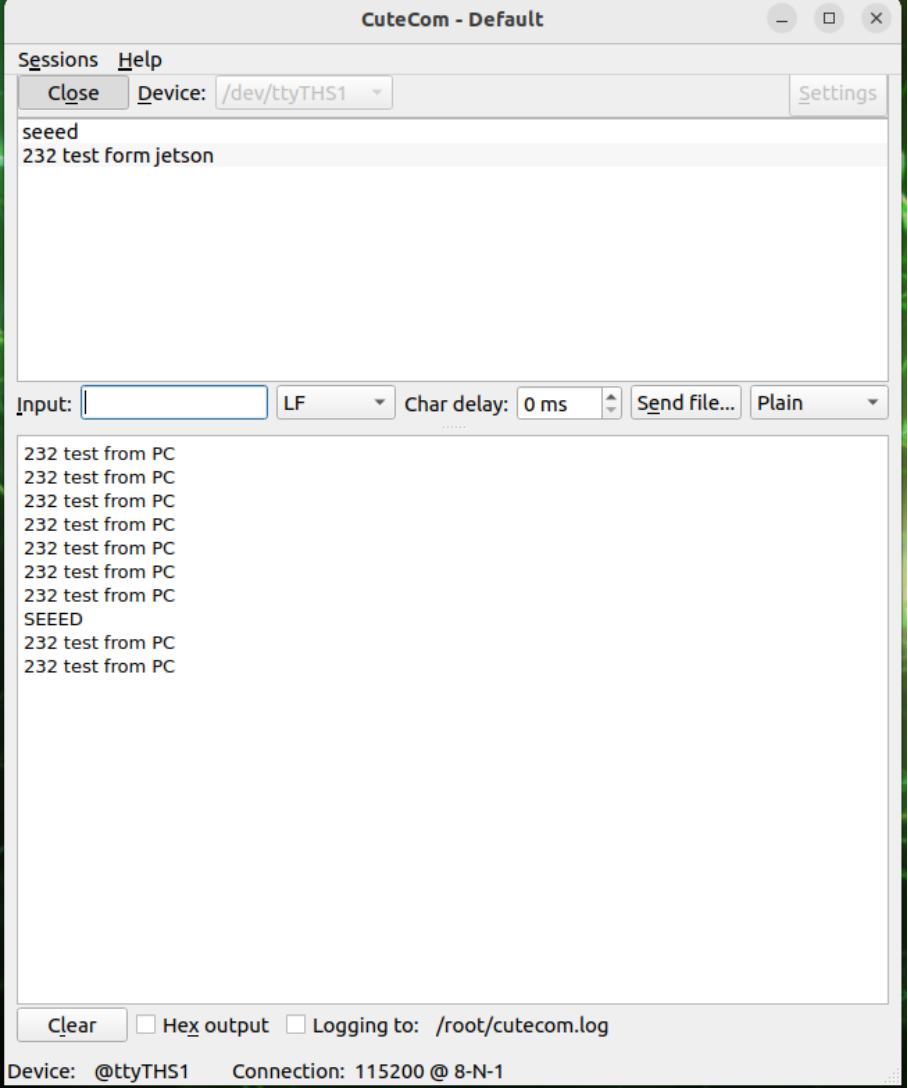
Step 1: Start CuteCom
Run sudo cutecom to start the CuteCom terminal software.
Step 2: Configure Serial Port Parameters Configure the serial port with the following parameters:
- Device:
/dev/ttyTHS1(UART1) or/dev/ttyTHS4(UART2) - Baud Rate: 115200 bps
- Data Bits: 8, Parity: None, Stop Bits: 1, Flow Control: None
Step 3: Open Serial Port Click "Open Device" to open the serial port.
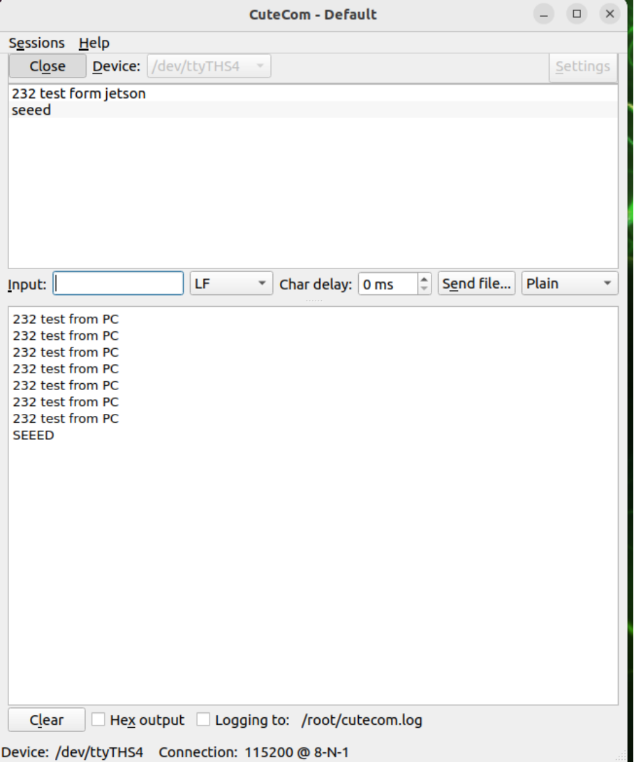
Step 4: Send Test Data Send test data (e.g., "232 test from jetson") and verify data reception from the peripheral device.
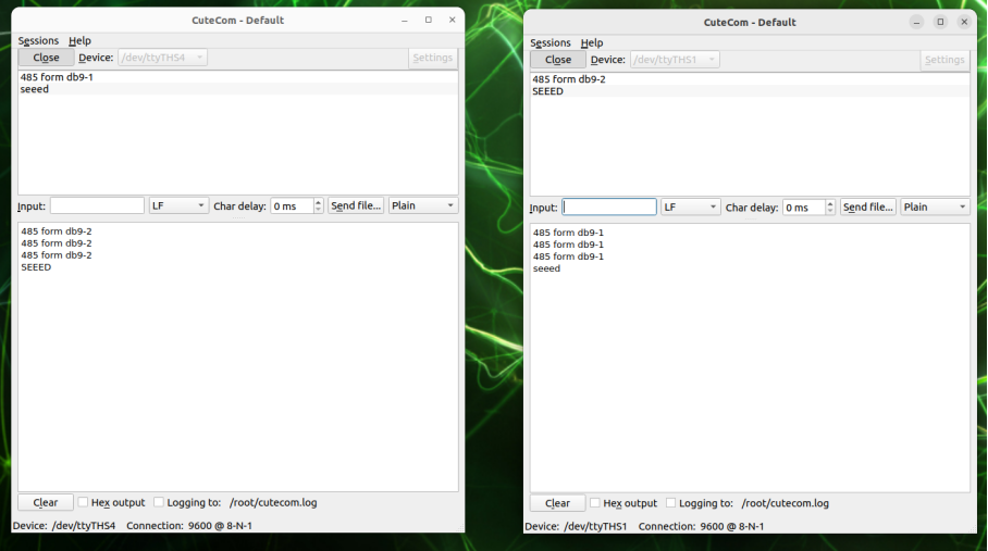
RS485 Mode Test
Here you can use a USB to RS485 adapter to test the interface. We have used DTech USB to RS485 Adapter for our testing.
The wiring diagram is shown below:
Step 1: Start CuteCom
Run sudo cutecom to start the CuteCom terminal software.
Step 2: Configure Serial Port Parameters Configure the serial port with the following parameters:
- Device:
/dev/ttyTHS1 - Baud Rate: 9600 bps
- Data Bits: 8, Parity: None, Stop Bits: 1, Flow Control: None
Step 3: Open Serial Port Click "Open Device" to open the serial port.
Step 4: Send Test Data Send test data (e.g., "485 test from jetson") and verify data reception from the peripheral device.
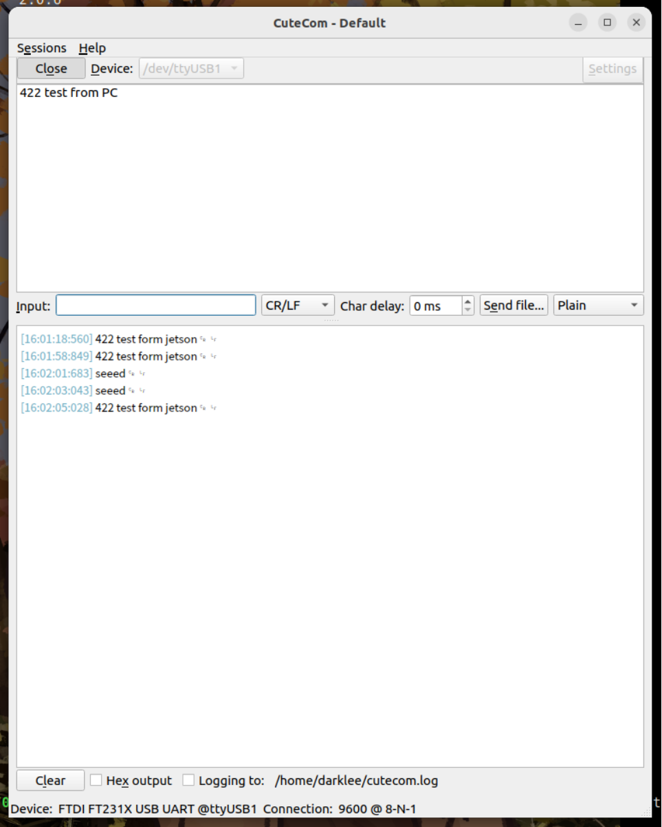
RS422 Mode Test
Here you can use a USB to RS422 adapter to test the interface. We have used DTech USB to RS485 Adapter for our testing.
The wiring diagram is shown below:
Step 1: Start CuteCom
Run sudo cutecom to start the CuteCom terminal software.
Step 2: Configure Serial Port Parameters Configure the serial port with the following parameters:
- Device:
/dev/ttyTHS1 - Baud Rate: 9600 bps
- Data Bits: 8, Parity: None, Stop Bits: 1, Flow Control: None
Step 3: Open Serial Port Click "Open Device" to open the serial port.
Step 4: Send Test Data Send test data (e.g., "422 test from jetson") and verify data reception from the peripheral device.
RTC
The reComputer Robotics J501 includes a hardware RTC with battery backup for accurate timekeeping. There are two ways to provide backup power to the RTC:
- Using the CR1220 coin cell battery holder (J14)
- Using the RTC 2-Pin Header - J4 for external power connection
Hardware Connection
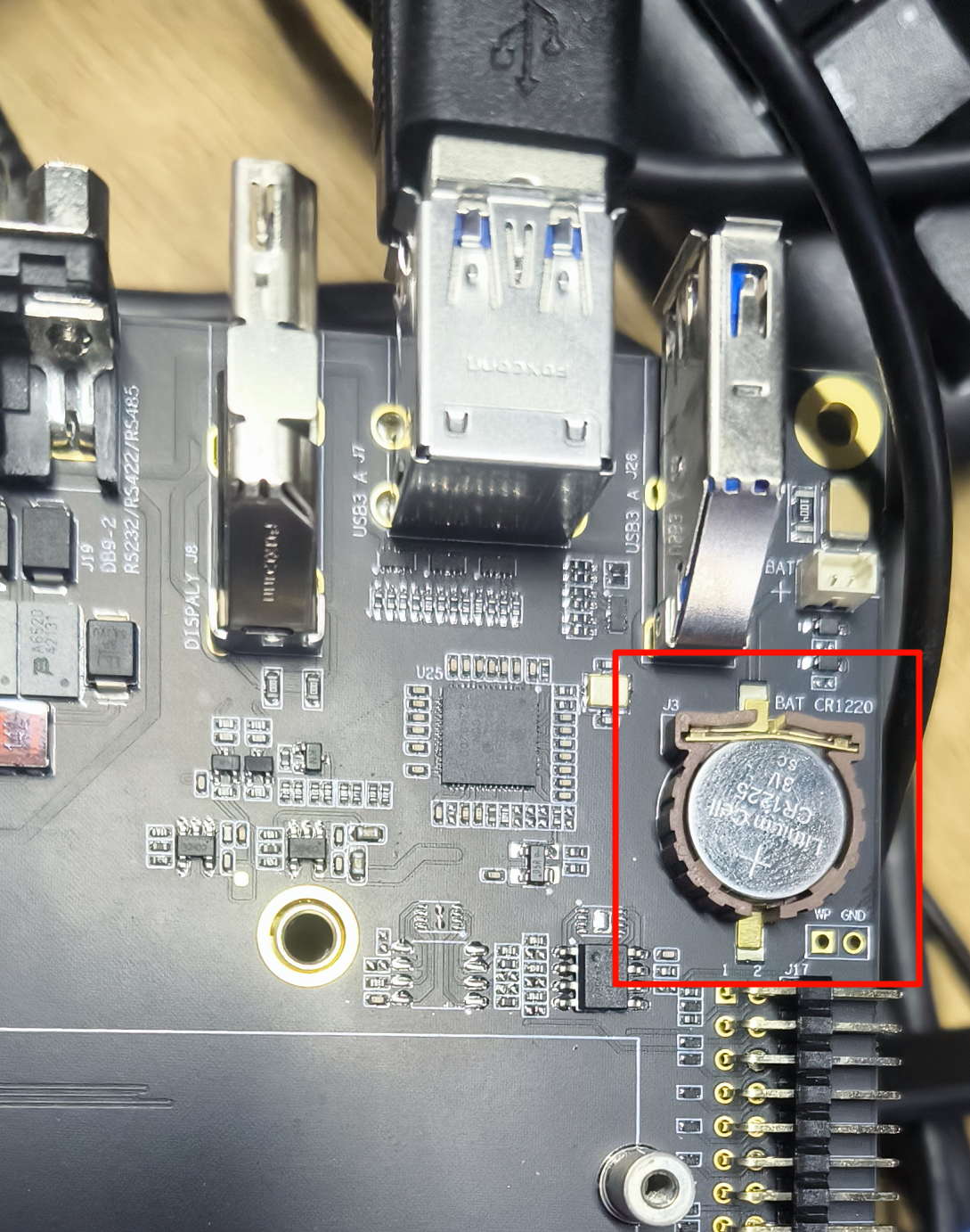
Method 1: Using CR1220 Coin Cell Battery Holder
Connect a 3V CR1220 coin cell battery to the RTC socket on the board as shown below. Make sure the positive (+) end of the battery is facing upwards.
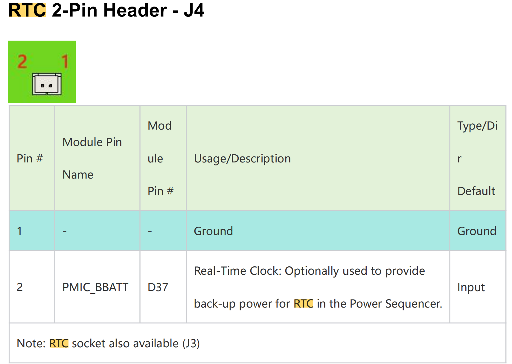
Method 2: Using RTC 2-Pin Header
The RTC 2-Pin Header provides an alternative way to connect external power to the RTC.
Usage Instruction
Step 1. Connect an RTC battery as mentioned above.
Step 2. Turn on reComputer Robotics J501.
Step 3. On the Ubuntu Desktop, click the drop-down menu at the top right corner, navigate to Settings > Date & Time, connect to a network via an Ethernet cable and select Automatic Date & Time to obtain the date/ time automatically.
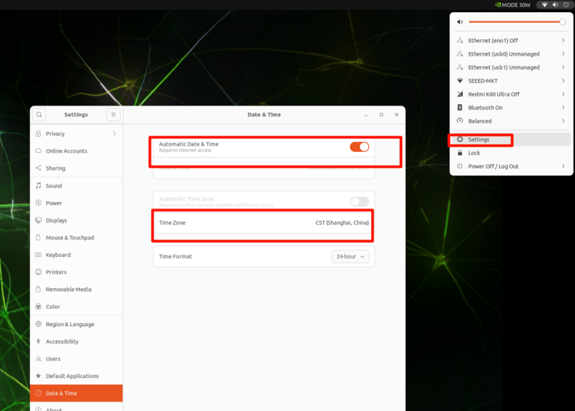
If you have not connected to internet via Ethernet, you can manually set the date/ time here.
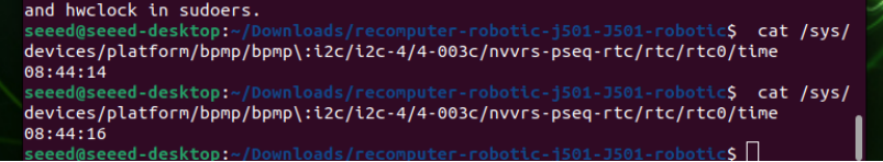
Step 4. Open a terminal window, and execute the below command to check the hardware clock time:
cat /sys/devices/platform/bpmp/bpmp\:i2c/i2c-4/4-003c/nvvrs-pseq-rtc/rtc/rtc0/time
Step 5. Disconnect the network connection and reboot the device. You will find that the system time has lost power but still functions normally.
Display
The Robotics J501 is equipped with an HDMI for high-resolution display output.
Extension Port
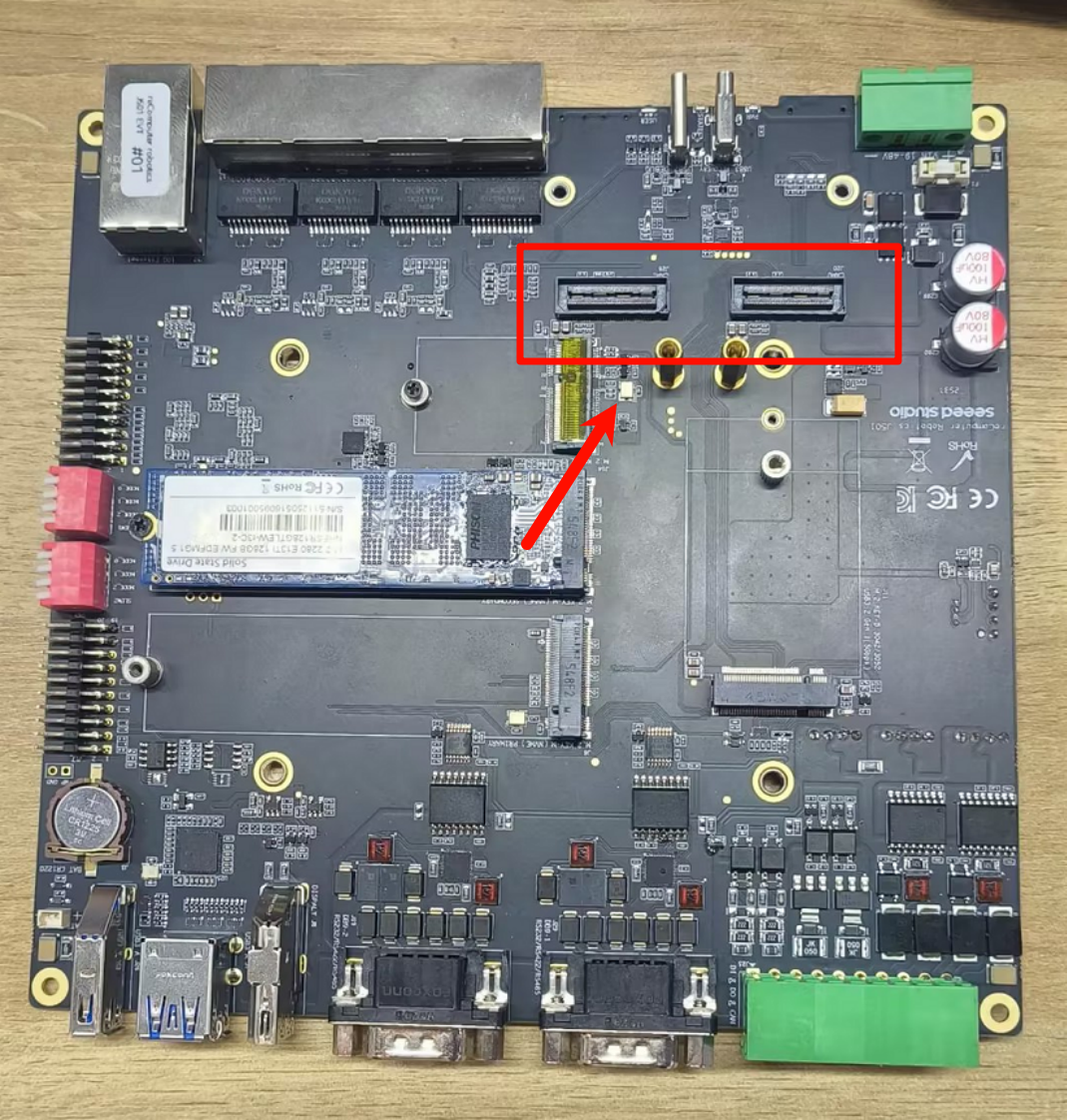
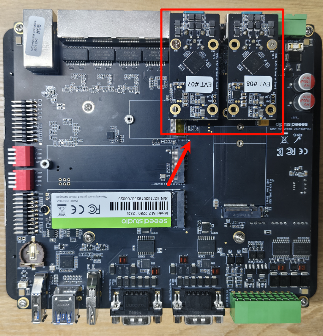
The Robotics J501 carrier board features a Camera Expansion Header for GMSL extension board. It can simultaneously connect and operate four GMSL cameras at the same time.
Hardware Connection
Here are the Robotics J501 carrier board GMSL camera expansion board connection slot(need to prepare an extension board in advance):
The following are the GMSL camera models that we have already supported:
- SG3S-ISX031C-GMSL2F
- SG2-AR0233C-5200-G2A
- SG2-IMX390C-5200-G2A
- SG8S-AR0820C-5300-G2A
- Orbbec Gemini 335Lg
Usage Instruction
Before enabling the GMSL functionality, please ensure that you have installed a JetPack version with the GMSL expansion board driver.
Configure the Jetson IO file
sudo /opt/nvidia/jetson-io/jetson-io.py
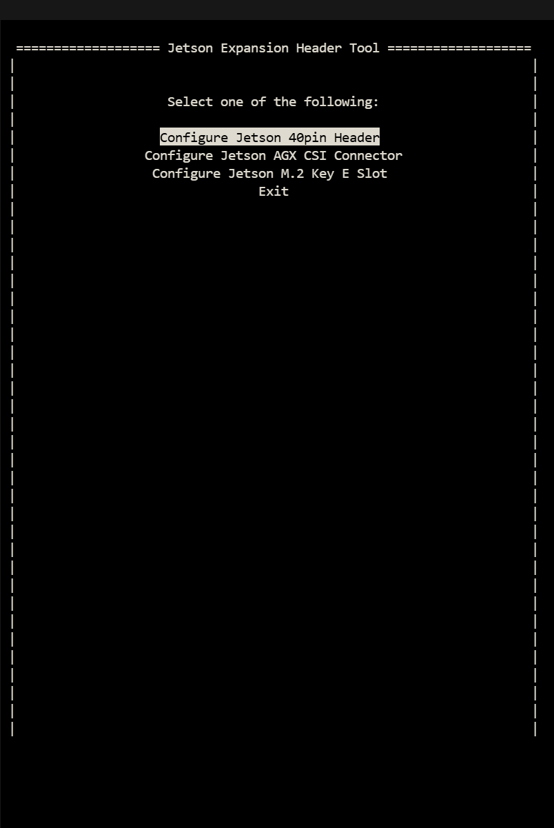
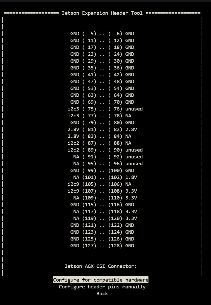
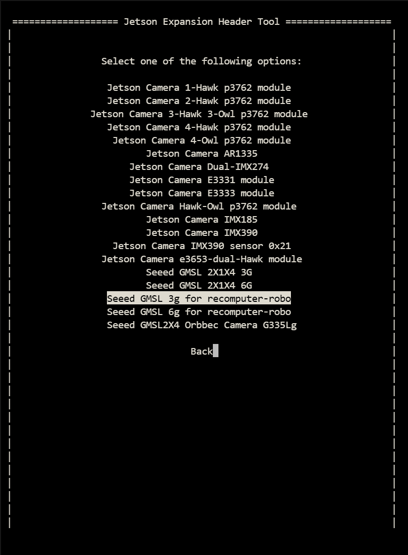
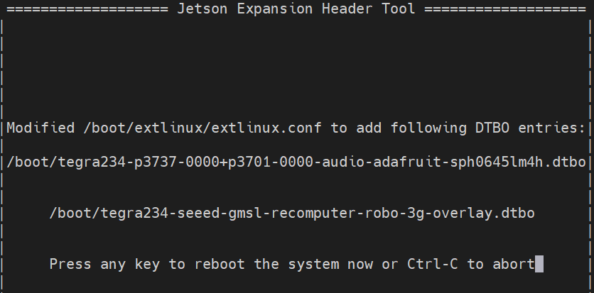
There are three overlay files in total, namely Seeed GMSL 1X4 3G, Seeed GMSL 1X4 6G, Seeed GMSL 1X4, and Orbbec Gemini 335Lg. These correspond to the 3G camera of SG3S, the 6G camera of SG2 and SG8S, and the camera of Orbbec respectively. As shown in Figure 3, please configure the io file according to the model of your camera.
step 2. Install the video interface configuration tools.
sudo apt update
sudo apt install v4l-utils wmctrl
Use the cameras of SGxxx Series
step 1. Set frame synchronization mode(It is not enabled by default!).
Here we demonstrate how to configure cameras of different models and resolutions.
#enables frame synchronization
v4l2-ctl -d /dev/video0 --set-ctrl=trig_mode=1
#Set the frame rate of the camera
v4l2-ctl -V --set-fmt-video=width=1920,height=1536 -c sensor_mode=0 --stream-mmap -d /dev/video0
#Set the camera format
v4l2-ctl -V --set-fmt-video=width=1920,height=1536 -c sensor_mode=0 -d /dev/video0
trig_mode = 1 enables frame synchronization, while trig_mode = 0 disables frame synchronization. The default setting is to disable frame synchronization.
--set-fmt-video follows the resolution which is selected based on the camera being connected. Currently, there are three sensor_mode options, each corresponding to a different resolution.
- sensor_mode=0 -------> YUYV8_1X16/1920x1536
- sensor_mode=1 -------> YUYV8_1X16/1920x1080
- sensor_mode=2 -------> YUYV8_1X16/3840x2160
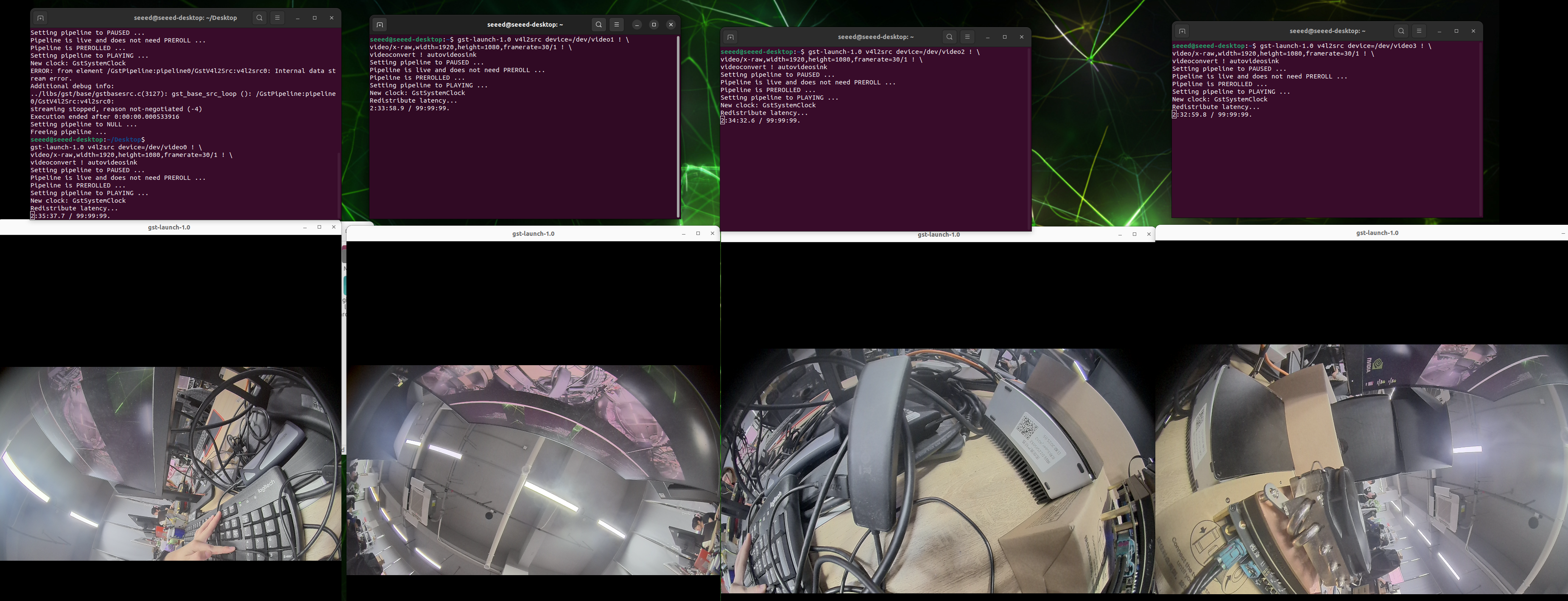
step 2. Start the camera.
gst-launch-1.0 \
    v4l2src device=/dev/video0 ! \
    video/x-raw,format=YUY2,width=1920,height=1080,framerate=30/1 ! \
    videoconvert ! \
    videoscale ! \
    xvimagesink

gst-launch-1.0 \
    v4l2src device=/dev/video1 ! \
    video/x-raw,format=YUY2,width=1920,height=1080,framerate=30/1 ! \
    videoconvert ! \
    videoscale ! \
    xvimagesink

gst-launch-1.0 \
    v4l2src device=/dev/video2 ! \
    video/x-raw,format=YUY2,width=1536,height=1080,framerate=30/1 ! \
    videoconvert ! \
    videoscale ! \
    xvimagesink

gst-launch-1.0 \
    v4l2src device=/dev/video3 ! \
    video/x-raw,format=YUY2,width=3840,height=2160,framerate=30/1 ! \
    videoconvert ! \
    videoscale ! \
    xvimagesink
Resources
- reComputer Robotics J501 Carrier Board Schematic
- reComputer Robotics J501 Carrier Board Datasheet
- Seeed NVIDIA Jetson Product Catalog
- Nvidia Jetson Comparison
- Seeed Nvidia Jetson Success Cases
- Seeed Jetson One Pager
- Source code of Seeed's L4T
Tech Support & Product Discussion
Thank you for choosing our products! We are here to provide you with different support to ensure that your experience with our products is as smooth as possible. We offer several communication channels to cater to different preferences and needs.