reComputer Rugged J401 Hardware and Interface Usage
This wiki introduces the various hardware and interfaces of reComputer Rugged J40 and explains how to use them to expand your project ideas. Most interfaces on the reComputer Rugged J40 use M12 connectors, providing IP66-rated water and dust resistance as well as excellent vibration resistance. This makes it suitable for long-term deployment in harsh outdoor environments, such as onboard vessels and in port monitoring systems.
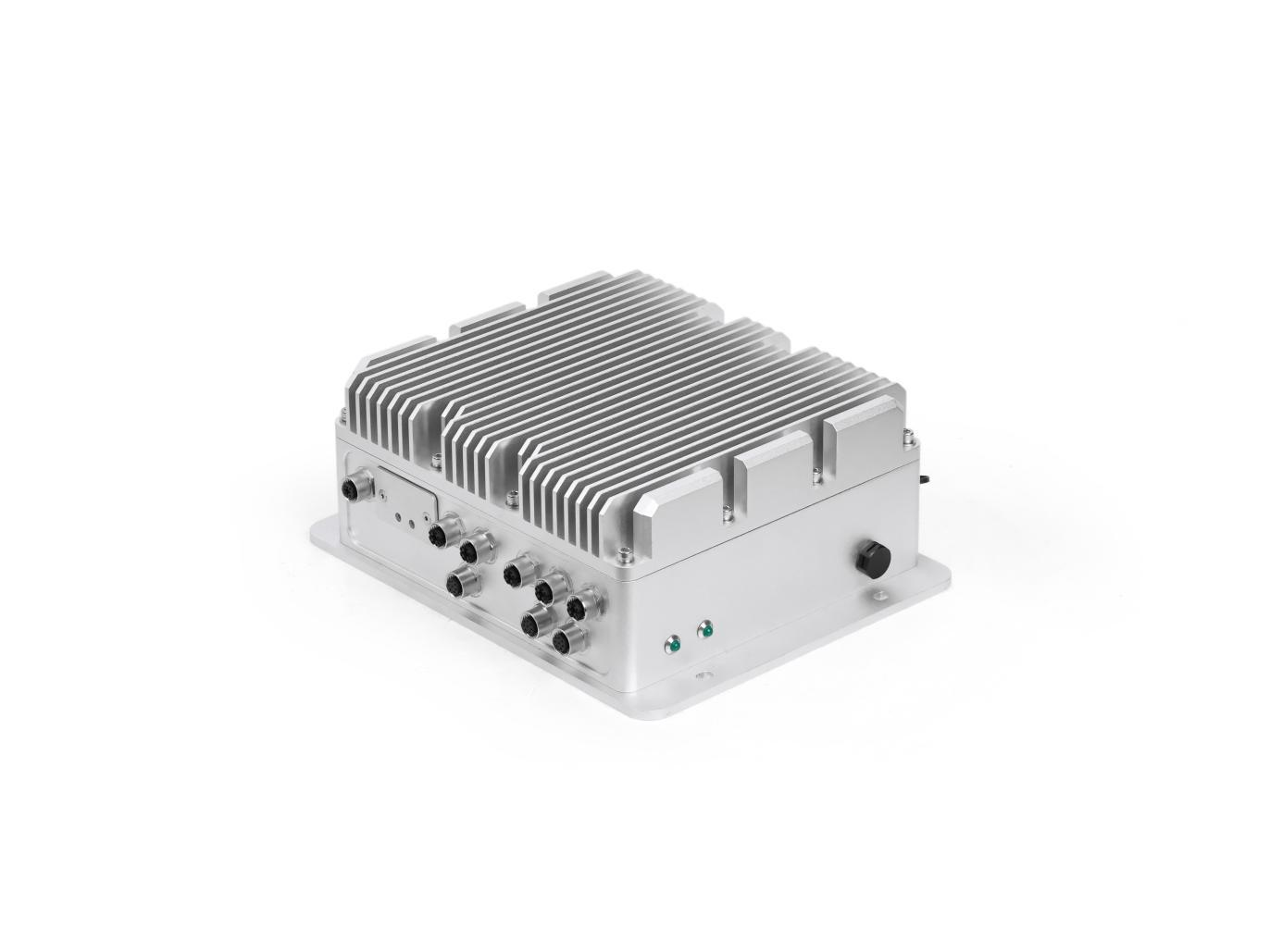
Hardware Overview
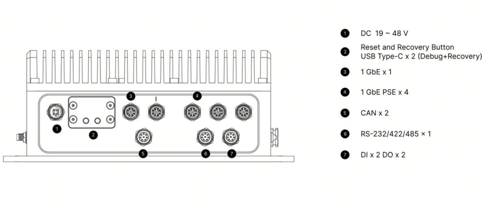
Side View 1
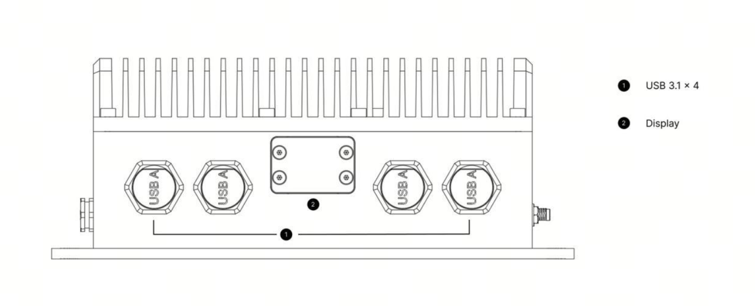
Side View 2
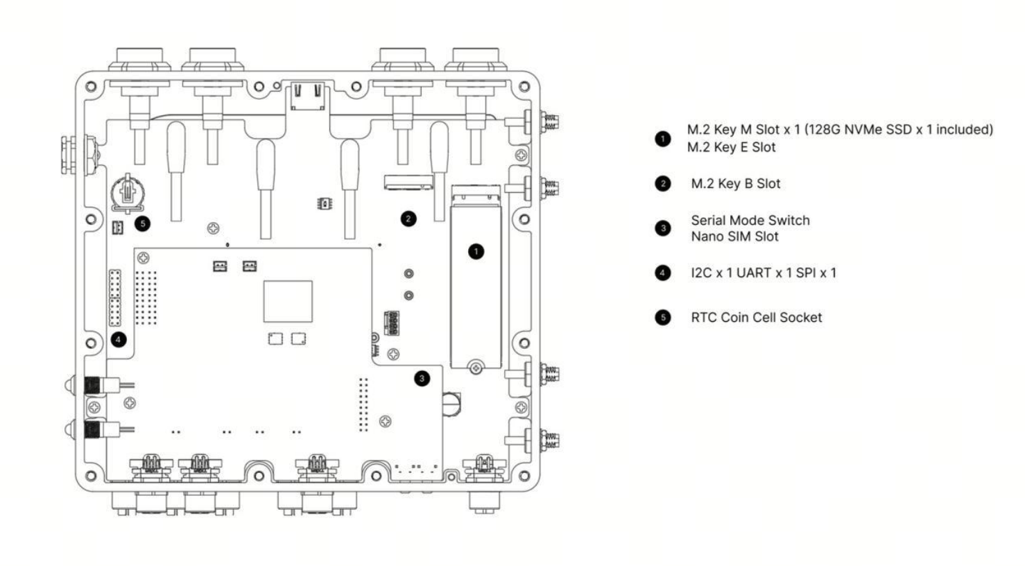
Bottom View
Carrier Board Specifications
| Item | Specification | |
|---|---|---|
| I/O | Ethernet | 1× M12 GbE + 4× M12 GbE PSE (IEEE 802.3af, 15 W, 10/100/1000 Mbps) |
| USB | 4× USB 3.2 Type-A (waterproof connectors) + 1× USB 3.0 Type-C (device / flashing) + 1× USB 2.0 Type-C (debug) | |
| Display | 1× HDMI 2.1 (waterproof cap) | |
| CAN | 2× CAN-FD (isolated) via M12 A-code | |
| Serial | 1× RS-232/422/485 via M12 A-code | |
| DI/DO | 2× DI + 2× DO via M12 A-code | |
| SIM | 1× Nano-SIM card slot | |
| Antenna | 4× SMA waterproof antenna connectors | |
| Storage | M.2 Key M | 1× M.2 Key M for NVMe 2280 SSD (128 GB SSD included) |
| Expansion | M.2 Key E | 1× M.2 Key E for M.2 2230 Wi-Fi module (Wi-Fi 6 module included) |
| M.2 Key B | 1× M.2 Key B for 5G module | |
| Onboard | SPI / I2C | 1× SPI, 1× I2C (internal pin header) |
| RTC | RTC socket, 2-pin connector | |
| LED | 1× PWR LED (green), 1× SSD LED (green) | |
| Button | 1× Recovery button, 1× RST button | |
| Power | Input | M12 A-code DC 19–48 V |
Power
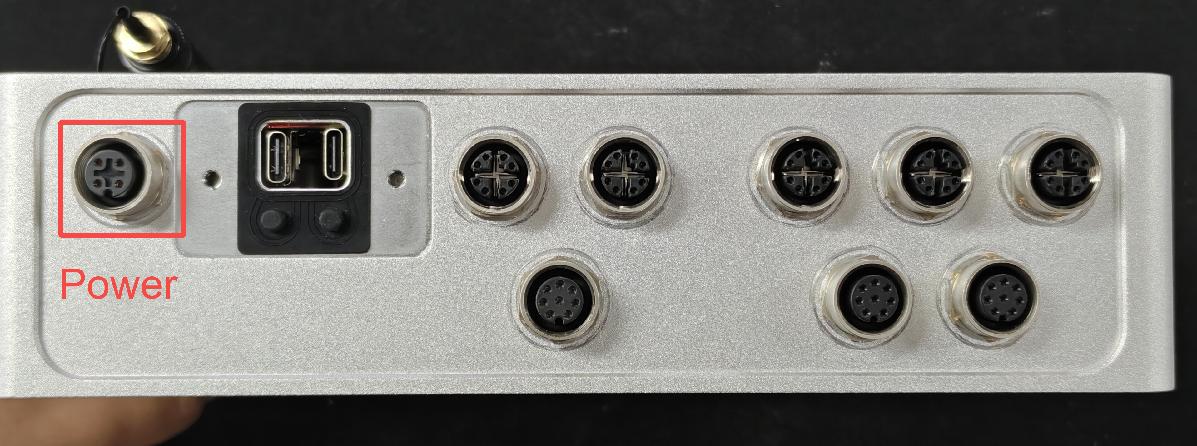
reComputer Rugged J401 is equipped with a M12 A-code DC 19-48V power interface, compatible with a wide voltage input range,making it suitable for various power supply environments.The interface definition is shown in the table below.
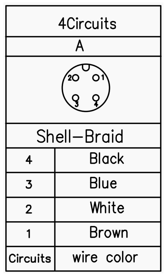
| Pin | Usage | Type | Wire Color |
|---|---|---|---|
| 1 | DC Power In | Power | Brown |
| 2 | White | ||
| 3 | Ground | Ground | Blue |
| 4 | Black |
Display
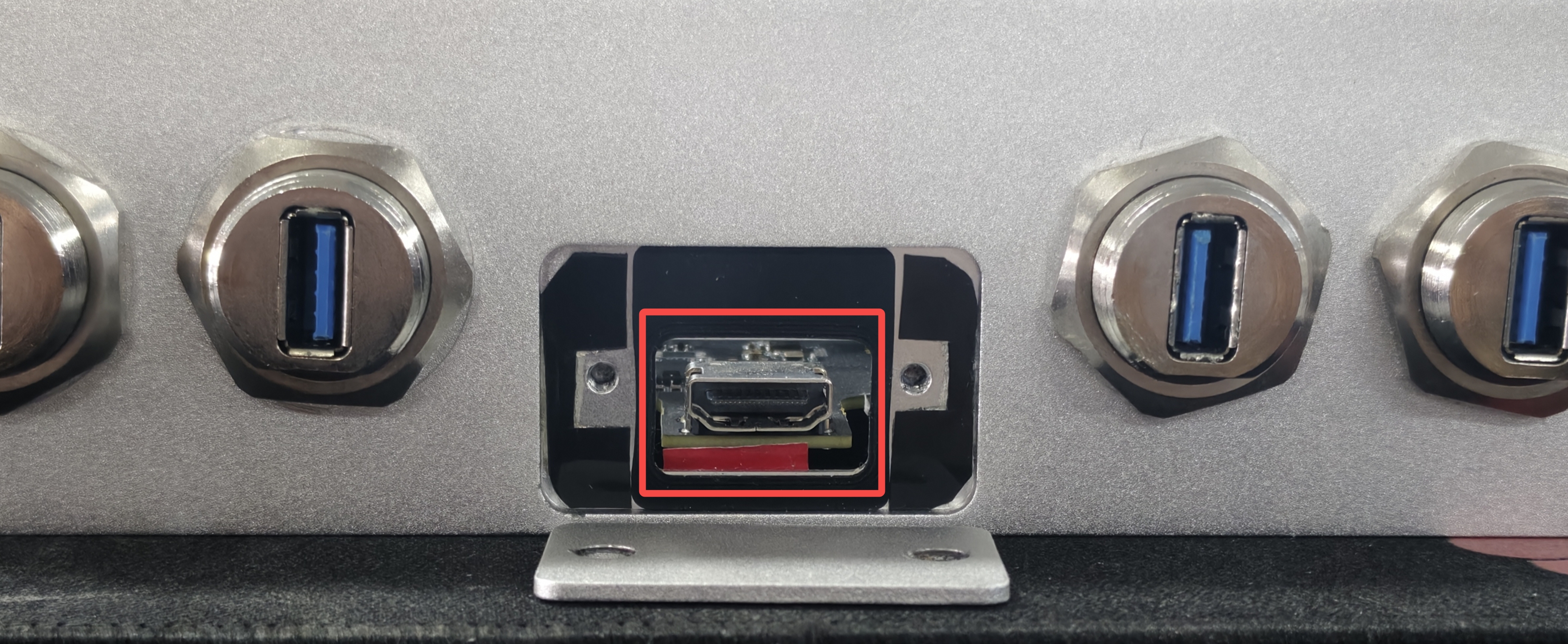
Remove the two screws securing the waterproof side cover and open it to access the HDMI 2.1 port, which provides high-quality display output.
M.2 Key M for SSD and M.2 Key E for Wi-Fi and Bluetooth
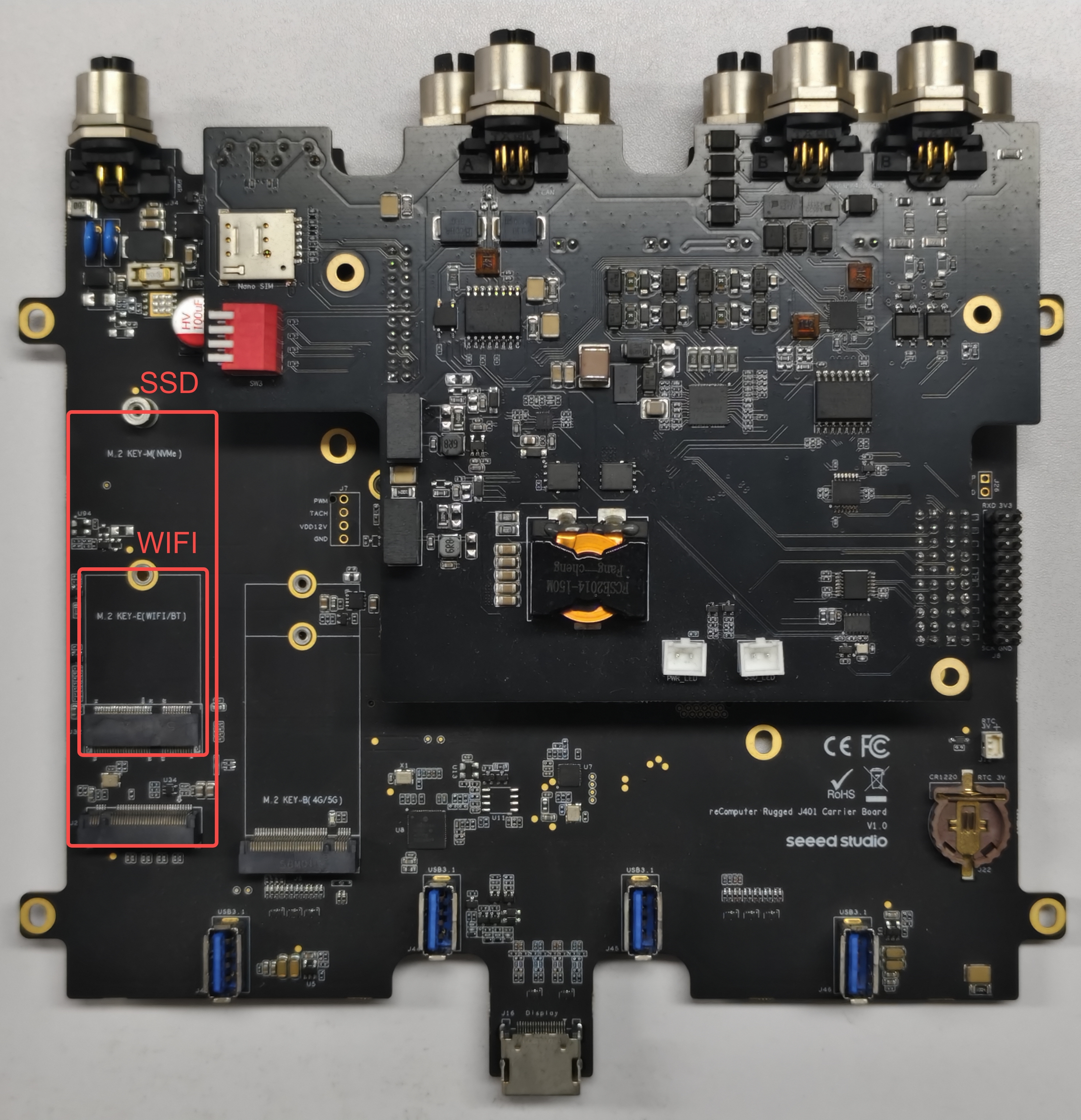
The reComputer Rugged J401 features a M.2 Key E interface, through which you can expand the device's Bluetooth and Wi-Fi capabilities.We recommend using the Intel Dual Band RTL8822CE Wireless NIC.
M.2 Key M is an interface designed for high-speed solid-state drives (SSDs), providing ultra-fast data transfer speeds, ideal for high-performance applications.
The interface location is shown in the figure below.
Usage Instruction
If you want to remove the included SSD and install a new one, you need to ensure that your SSD meets the following two conditions:
-
Support the M.2 Key M slot with x4 PCIe Gen3 interface.
-
Conform to the 2242 size specification.
Open the terminal in Jetson device and enter the following command to test the SSD's read and write speed.
sudo dd if=/dev/zero of=tempfile bs=1M count=1024 conv=fdatasync

Please run sudo rm tempfile command to delete the cache files after the test is complete.
After installing the Wi-Fi module and powering on the device, we can configure the device's Wi-Fi and Bluetooth settings.
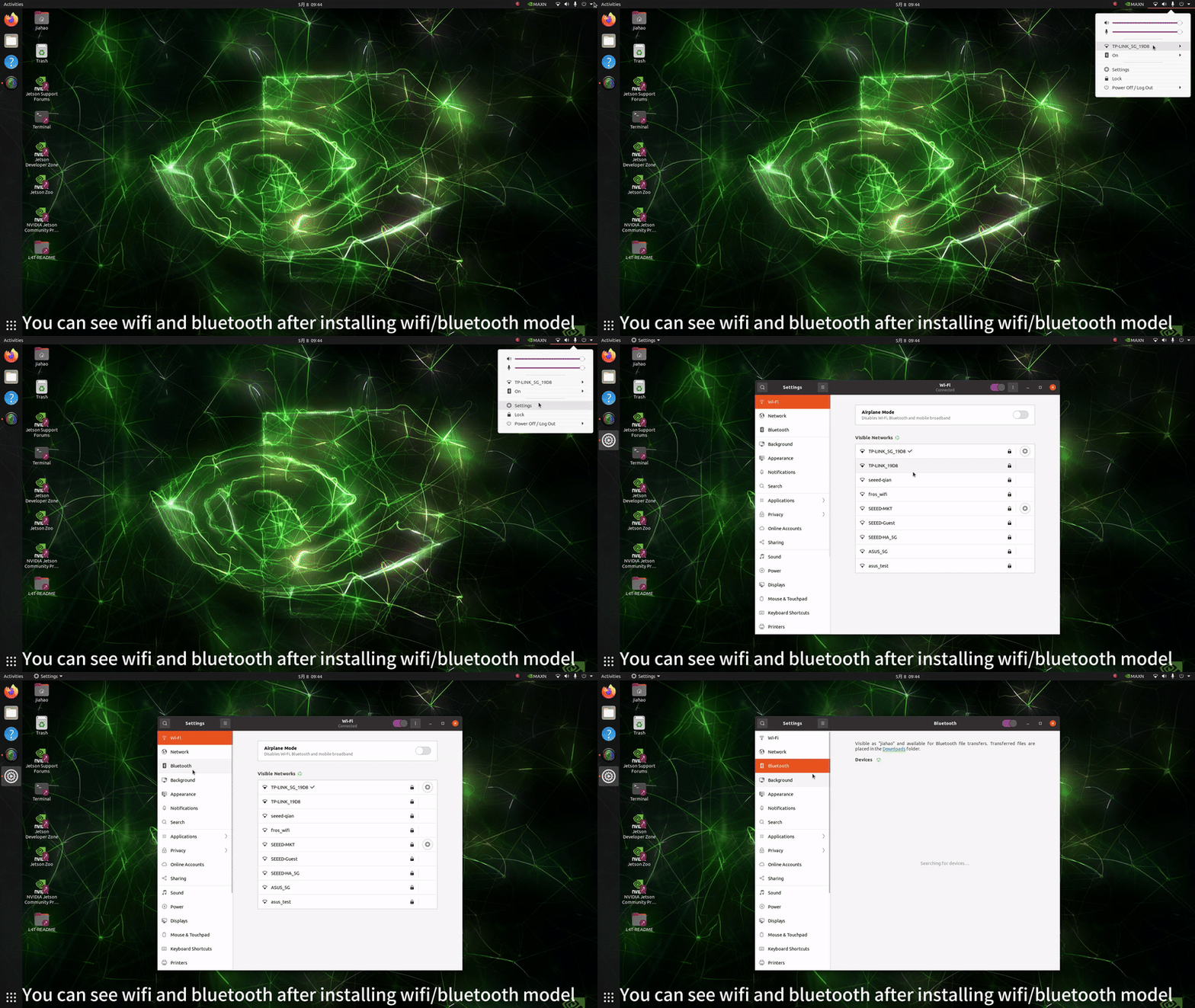
Of course, we can also check the device's operating status using the following commands.
ifconfig

bluetoothctl

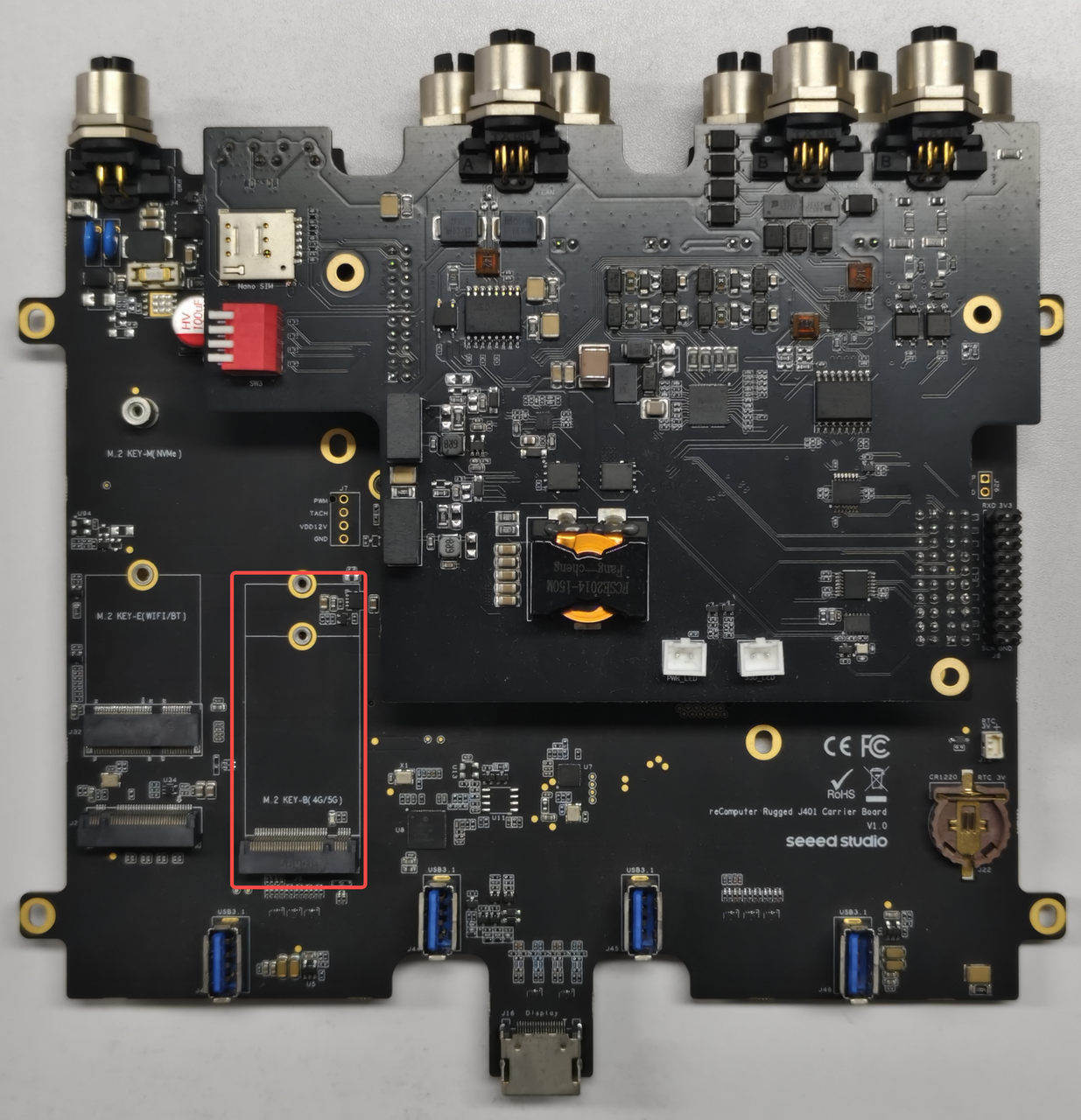
M.2 Key B for 4G/5G Module
The M.2 Key B slot supports 4G/5G cellular modules with Nano SIM card holder.
Hardware Connection
Usage Instruction
Step 1. Check Hardware Recognition
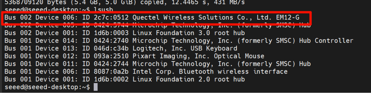
lsusb
This command displays a list of all USB devices connected to the system, along with their manufacturer (ID), type, and other information. For example, the output might show a device from Quectel Wireless Solutions Co., Ltd. EM12-G, indicating that the 5G module is present.
Step 2. Confirm Driver Loading
It's essential to ensure that the option driver, which is required for the 5G module, is loaded. We can use the lsmod command to check.
lsmod | grep option
If the option driver is loaded successfully, relevant information about the driver will be displayed in the output.

Step 3. Configure ModemManager
ModemManager is a tool for managing modem devices, and it needs to be installed and restarted.
sudo apt install modemmanager
sudo systemctl restart ModemManager
The apt install command is used to install the ModemManager package, while systemctl restart restarts the ModemManager service to ensure that the new settings take effect.
Step 4. Verify Module Identification
We can use the mmcli -L command to check if the ModemManager can correctly identify the 5G module.
mmcli -L
If the 5G module is recognized, an output similar to /org/freedesktop/ModemManager1/Modem/0 will be displayed, indicating the path to the detected modem device.

Step 5. Set the APN
APN (Access Point Name) is crucial for connecting a mobile device to the network.We'll use the nmcli command to create a bearer profile. Taking China Mobile as an example, we can create a configuration file with the following commands:
sudo nmcli con add type gsm ifname "*" apn "CMNET" ipv4.method auto
This command adds a new GSM (Global System for Mobile Communications) type connection, specifying the APN as "CMNET" and using automatic IPv4 configuration.
Step 6. Activate the Connection
After creating the bearer profile, we need to activate the connection.
sudo nmcli con up "gsm"
This command activates the GSM connection, and if successful, a confirmation message will be displayed.

Step 7. Re-verify Module Identification
Run the mmcli -L command again to ensure that the module remains recognized after configuring the APN.
mmcli -L
Step 8. Check Module Status
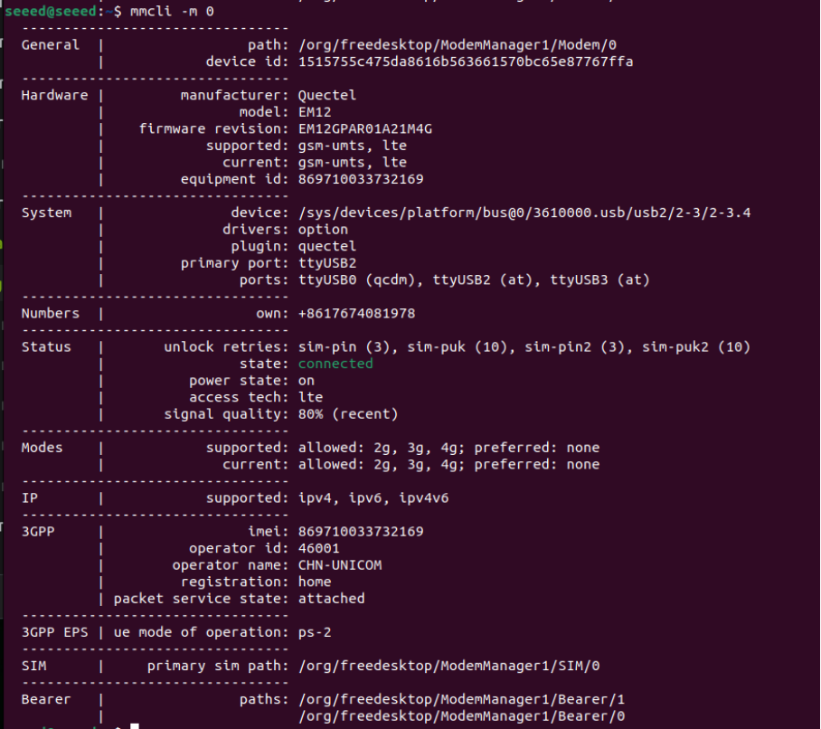
Finally, we can use the mmcli -m 0 command to view detailed information about the module, such as IP allocation, carrier, and network connection status.
mmcli -m 0
This command provides comprehensive details about the 5G module, including its manufacturer, model, supported and current network technologies, device status, and connected network operators.
Ethernet
The reComputer Rugged J401 provides 1x standard Gigabit Ethernet (10/100/1000M) RJ45 port (J35) and 4x Gigabit PSE (Power Sourcing Equipment) RJ45 ports (J36–J39). The standard Gigabit port is used for general network connectivity. The PSE ports support IEEE 802.3af/at standards, enabling power delivery over Ethernet to connected devices such as IP cameras and wireless access points, with a maximum output of 15.4W per port (802.3af). This makes it ideal for industrial, AMR, and outdoor edge computing applications, eliminating the need for separate power cabling. All Gigabit ports are derived from the PCIe controller within the Jetson Orin module and support 10/100/1000M auto-negotiation.
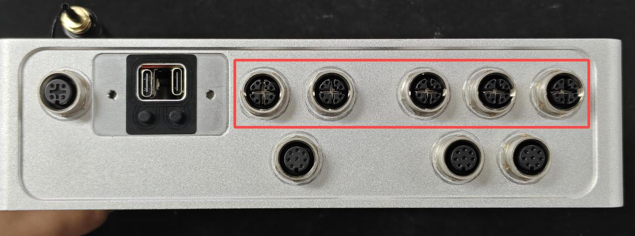
The Linux network device names map to the physical Ethernet ports as shown below. When viewing the Ethernet connectors from the same direction as the image, the mapping from left to right is eth4, eth2, eth1, eth0, and eth3.
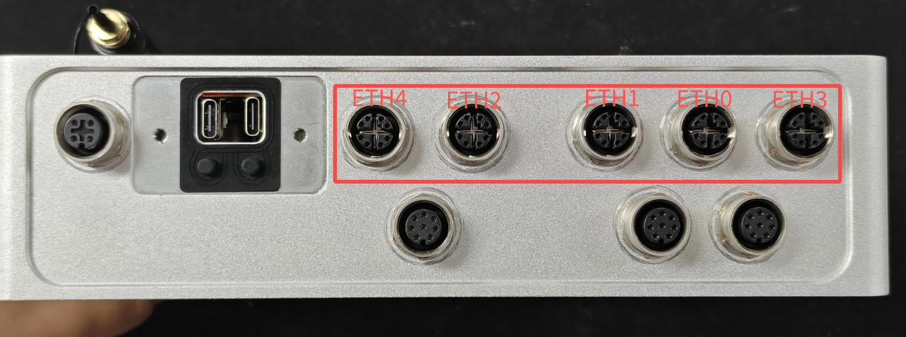
| Physical port position | Linux device name |
|---|---|
| First from the left | eth4 |
| Second from the left | eth2 |
| Center | eth1 |
| Second from the right | eth0 |
| First from the right | eth3 |
Use ethtool to check the negotiated bandwidth and physical link status of each Ethernet port. Install it first if the command is not available:
sudo apt update
sudo apt install -y ethtool
Run the following command to display the speed, duplex mode, auto-negotiation status, and link state for all five physical Ethernet interfaces:
for interface in eth0 eth1 eth2 eth3 eth4; do
  echo "=== ${interface} ==="
  sudo ethtool "${interface}" | grep -E 'Speed:|Duplex:|Auto-negotiation:|Link detected:'
done
Speed shows the negotiated link bandwidth, such as 1000Mb/s; Duplex should normally report Full; and Link detected: yes confirms that the corresponding physical port has an active connection. A disconnected port may report Speed: Unknown! and Link detected: no.
Usage Instruction
Hardware Connection
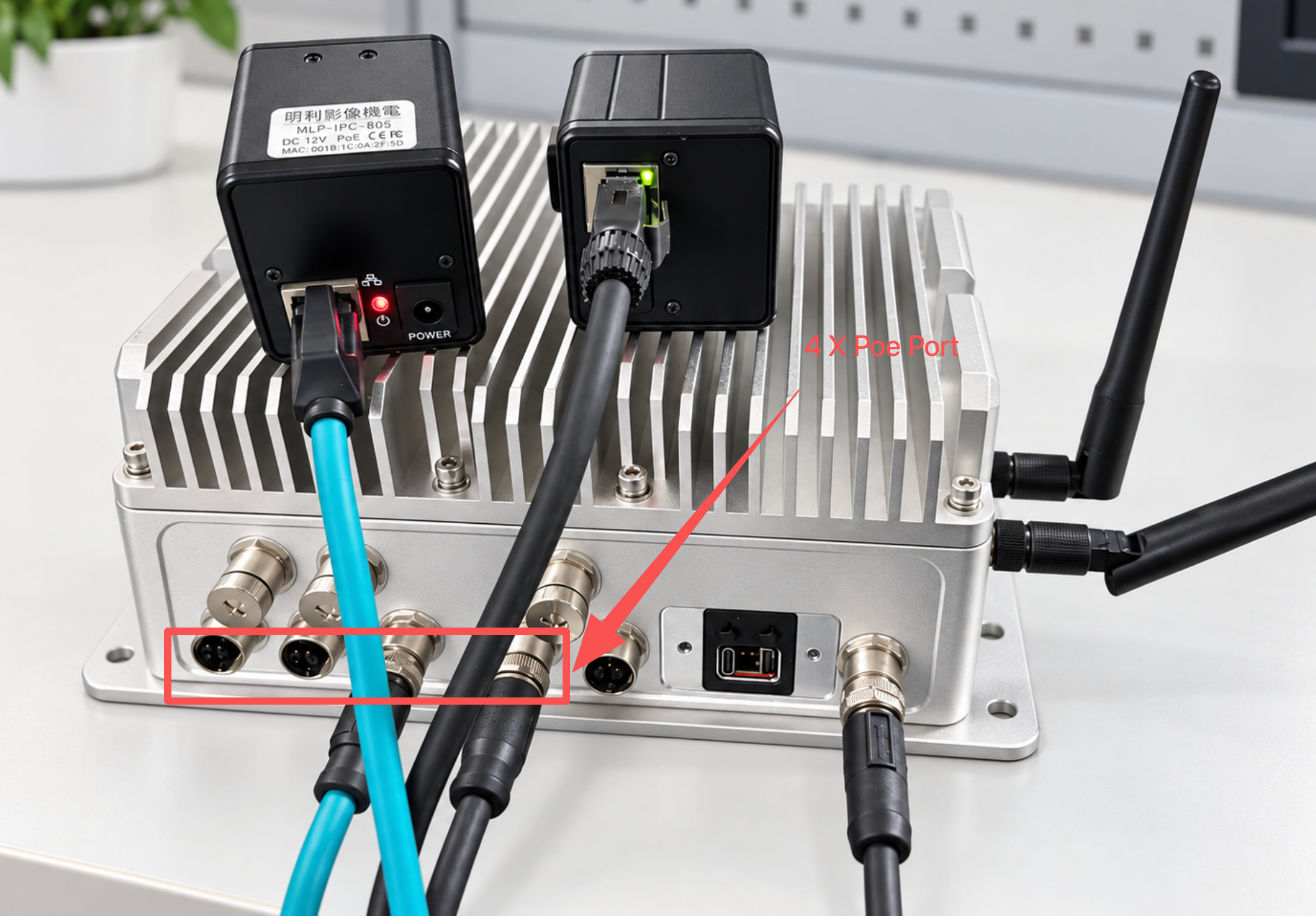
Enabling the PoE Output
The four PSE ports (J36–J39) are fed by an on-board PSE controller that is disabled by default. Nothing on a stock system switches it on, so a camera plugged into J36–J39 stays unpowered until the PSE power-enable line is driven high and kept high.
| Signal | GPIO | Direction | Meaning |
|---|---|---|---|
PSE_PWR_EN | gpiochip2 line 15 | output | drive high to switch the PSE output on |
PSE_PG | gpiochip2 line 0 | input | 1 = PSE power good |
PSE_INTB | gpiochip2 line 1 | input | 0 = no fault |
Install the GPIO tools if they are missing, then enable the output and keep it held:
sudo apt-get install -y gpiod     # only if gpioset/gpioget are not already present

# Set PSE_PWR_EN high and keep it high.
# -m signal  : maintain the level until the process receives SIGINT/SIGTERM
# setsid + & : detach it from the terminal so the hold survives the SSH session
sudo setsid gpioset -m signal 2 15=1 >/dev/null 2>&1 &

# Confirm the hold is alive
ps aux | grep "[g]pioset -m signal 2 15=1"

# Confirm the controller reports power good -> expected output: "1 0"
sudo gpioget gpiochip2 0 1
Expected Output:
1 0
1 0 means PSE_PG=1 (power good) and PSE_INTB=0 (no fault). If PSE_PG stays 0, no power is being delivered: check the cable and the camera's own power requirement (802.3af allows 15.4 W per port). If PSE_INTB reads 1, the controller has latched a fault — remove the load, power-cycle, and check again.
Important: the level is only driven while the gpioset process is alive. A GPIO line requested through the character device reverts to its default state when the last process holding it exits — gpioset --help states this explicitly — so running the command and letting it return does not keep the PSE on. After a reboot, or if the process is killed, the cameras lose power and the link goes down.
Keeping the PSE On Across Reboots (Optional)
Wrap the same hold in a systemd unit so it is applied at every boot and restarted automatically if it ever exits:
sudo tee /etc/systemd/system/poe-pse-hold.service >/dev/null <<'EOF'
[Unit]
Description=Hold PoE PSE power enable (PSE_PWR_EN gpio2/15)

[Service]
Type=simple
ExecStart=/usr/bin/gpioset -m signal 2 15=1
Restart=on-failure
RestartSec=2

[Install]
WantedBy=multi-user.target
EOF

sudo systemctl daemon-reload
sudo systemctl enable --now poe-pse-hold
systemctl status poe-pse-hold --no-pager
Type=simple plus Restart=on-failure is what makes this a hold rather than a one-shot command: systemd keeps the process — and therefore the GPIO level — alive.
Bringing Up Two PoE Cameras
With the PSE output enabled, two cameras can be powered and reached without any external PoE injector. Bringing them up by hand takes three steps.
Step 1. Find the ports that actually carry a camera. The five Gigabit ports enumerate as eth0–eth4; read the carrier flag instead of assuming which index belongs to which connector:
for i in eth0 eth1 eth2 eth3 eth4; do
  echo "$i carrier=$(cat /sys/class/net/$i/carrier 2>/dev/null) speed=$(cat /sys/class/net/$i/speed 2>/dev/null)"
done
Step 2. Let the cameras finish booting (30–60 s after PSE power comes up), then put the Jetson's port into the same subnet as each camera:
sleep 45

sudo ip link set eth1 up
sudo ip addr add 192.168.10.100/24 dev eth1     # camera A is 192.168.10.20
sudo ip link set eth2 up
sudo ip addr add 192.168.20.100/24 dev eth2       # camera B is 192.168.20.10
Step 3. Verify the links and the two cameras:
ping -c2 -W1 192.168.10.20
ping -c2 -W1 192.168.20.10
ip -br addr show eth1
ip -br addr show eth2
Expected Output: both pings report 0% packet loss, and each port shows UP with the address you assigned:
eth1             UP             192.168.10.100/24
eth2             UP             192.168.20.100/24
Notes:
- Each camera keeps the address it was configured with. If you do not know it, put the port into the subnet the camera should be on and look for it with a ping sweep.
- A port that stays at
carrier=0whilePSE_PG=1means the camera is not drawing power, or the waterproof connector is not fully seated. - The addresses above are examples taken from a two-camera setup; use the subnets of your own cameras.
ip addr addis not persistent across reboots — configure the port with NetworkManager orsystemd-networkdif it has to survive a restart.
# find an unknown camera on a port (example subnet)
for ip in $(seq 2 254); do ping -c1 -W1 192.168.10.$ip >/dev/null 2>&1 && echo "192.168.10.$ip is up"; done
Dual-Camera Live Preview
Both RTSP streams can be displayed at once, each in its own GStreamer window. Use the GPU/EGL path for the first window and the X11/Xv path for the second: two EGL-based sinks running at the same time can crash the EGL display on this platform.
# Window A - GPU/EGL path
nohup env DISPLAY=:0 XAUTHORITY=/home/seeed/.Xauthority gst-launch-1.0 \
  rtspsrc location="rtsp://<user>:<password>@192.168.10.20:554/" protocols=tcp latency=200 ! \
  rtph265depay ! h265parse ! nvv4l2decoder ! \
  nvvidconv ! "video/x-raw(memory:NVMM),width=1152,height=648" ! \
  nvegltransform ! nveglglessink sync=false > /tmp/camA_disp.log 2>&1 &

# Window B - X11/Xv path
nohup env DISPLAY=:0 XAUTHORITY=/home/seeed/.Xauthority gst-launch-1.0 \
  rtspsrc location="rtsp://<user>:<password>@192.168.20.10:554/" protocols=tcp latency=200 ! \
  rtph265depay ! h265parse ! nvv4l2decoder ! \
  nvvidconv ! "video/x-raw,width=1280,height=720" ! \
  xvimagesink sync=false > /tmp/camB_disp.log 2>&1 &
- Replace
<user>:<password>with the credentials of your own camera, and the IP addresses with the ones you verified above. DISPLAY=:0andXAUTHORITY=/home/seeed/.Xauthorityare needed when the commands are launched over SSH; adjust the path if your desktop user is notseeed. Running them from a terminal inside the JetPack desktop session needs neither.protocols=tcpis used because RTSP over UDP is often blocked or lossy on industrial networks, andlatency=200gives the stream a 200 ms jitter buffer.- The cameras tested here stream H.265. Check your own camera and swap the depayloader/parser pair if it is H.264.
- The first frames appear after a few seconds (RTSP handshake, decoder warm-up and the camera's keyframe interval). If a window stays black, read
/tmp/camA_disp.logor/tmp/camB_disp.log. - Stop the preview with
pkill -f "gst-launch-1.0.*rtspsrc", orkill %1 %2if both were started from the same shell.
To read the codec of a stream:
timeout 20 gst-launch-1.0 -v rtspsrc location="rtsp://<user>:<password>@192.168.10.20:554/" \
  protocols=tcp latency=200 ! fakesink 2>&1 | grep -o "encoding-name=(string)H26[45]" | head -1
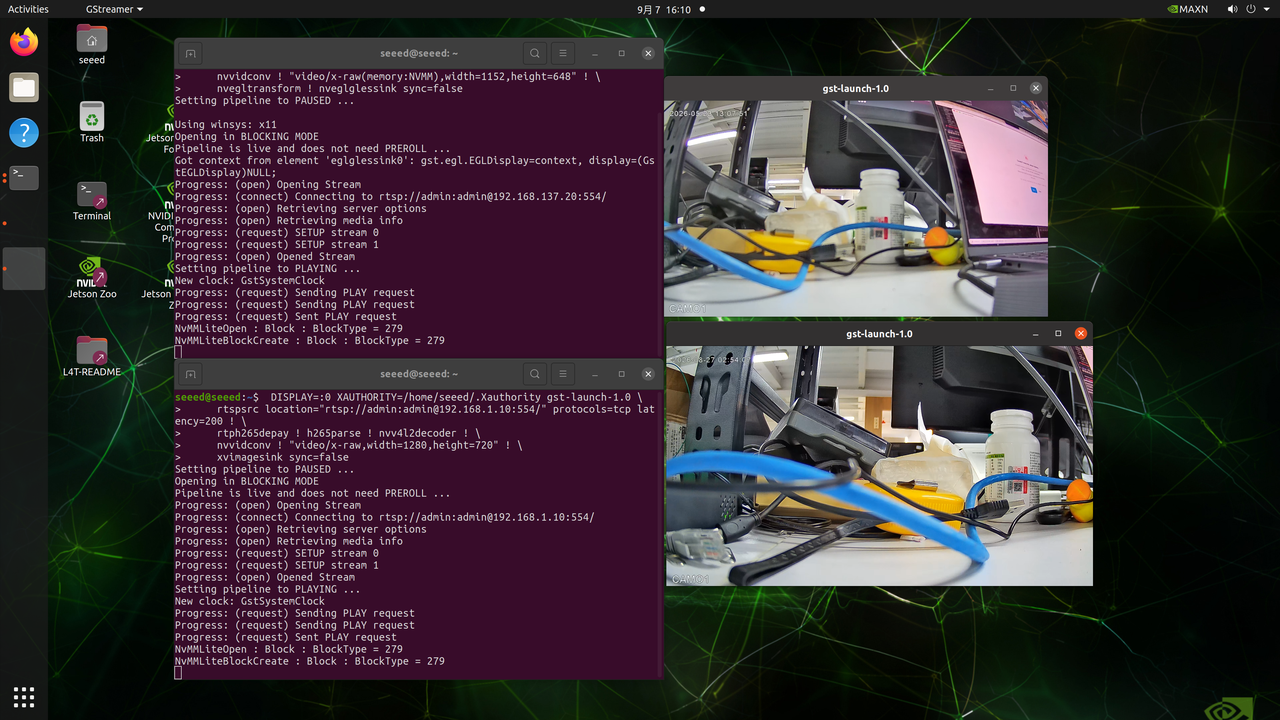
For an H.264 camera use rtph264depay ! h264parse instead of rtph265depay ! h265parse; the rest of the pipeline is unchanged.
USB
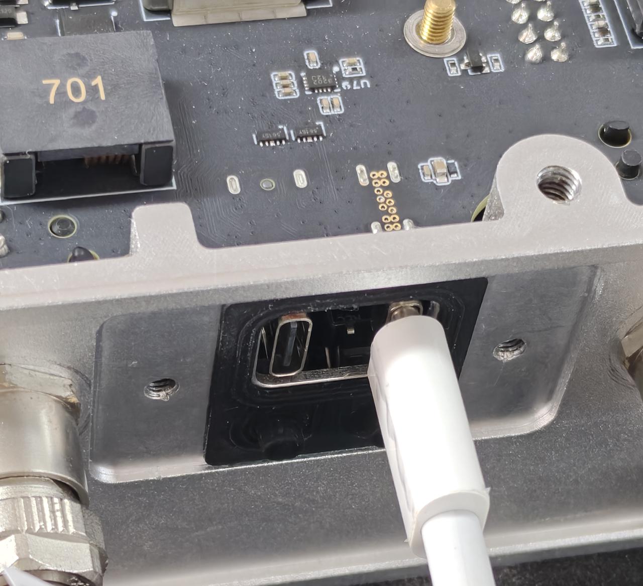
The reComputer Rugged J401 provides 4x USB 3.2 Type-A ports (via an internal USB 3.1 Gen1 hub, supporting up to 5Gbps data rates for connecting high-speed peripherals, storage devices, or cameras) and 1x USB 2.0 Type-C debug port (which functions as a serial console for accessing system logs, debugging boot issues, and performing firmware updates).
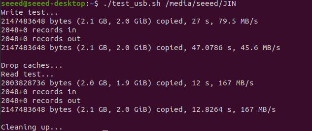
USB-A Speed test
Create a script to test USB device speed:
vim test_usb.sh
Paste the following content:
cat <<'EOF' | sudo tee test_usb.sh >/dev/null
#!/bin/bash
set -e

MOUNT_POINT="$1"
TEST_FILE="$MOUNT_POINT/test_usb_speed.bin"

if [ -z "$MOUNT_POINT" ]; then
  echo "Usage: $0 <mount_point>"
  echo "Example: $0 /media/seeed/USB"
  exit 1
fi

if [ ! -d "$MOUNT_POINT" ]; then
  echo "Error: $MOUNT_POINT is not a directory"
  exit 1
fi

echo "Write test..."
dd if=/dev/zero of="$TEST_FILE" bs=1M count=2048 conv=fdatasync status=progress

echo
echo "Drop caches..."
sync
echo 3 | sudo tee /proc/sys/vm/drop_caches >/dev/null

echo "Read test..."
dd if="$TEST_FILE" of=/dev/null bs=1M count=2048 status=progress

echo
echo "Cleaning up..."
rm -f "$TEST_FILE"
EOF
Press Esc to exit Insert mode, then type :w and press Enter to save the script, and then exit the process.
Make the script executable and test:
sudo chmod +x test_usb.sh
./test_usb.sh /mnt          # If your USB drive is mounted at /mnt
# Or
./test_usb.sh /media/usb    # If your USB drive is mounted at /media/usb
# Or
./test_usb.sh /path/to/your/usb/mount_point
USB 2.0 Type-C port
Using this serial port, via the USB-C data cable, you can monitor the debugging information of input and output on the PC side.
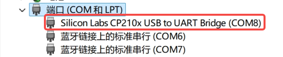
Install the Silicon Labs CP210x Universal Windows VCP Driver on Windows.
In Device Manager, locate and confirm the COM port assigned to the serial device
(COM8 in the screenshot).
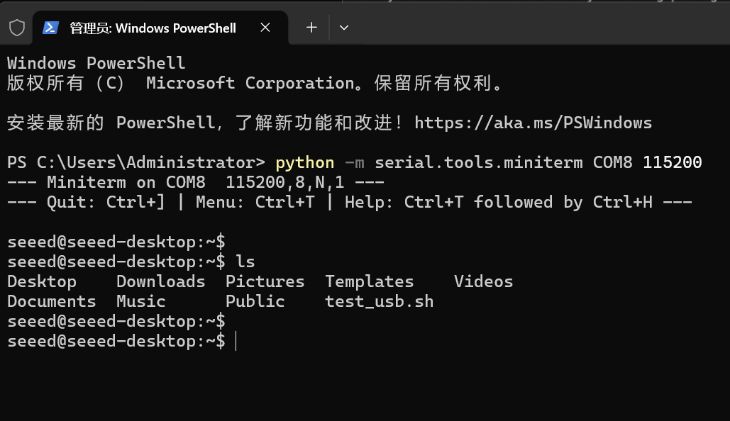
Run the following commend in PowerShell:
#Choose your own serial port
python -m serial.tools.miniterm COM8 115200
Log in with username and password.
RTC
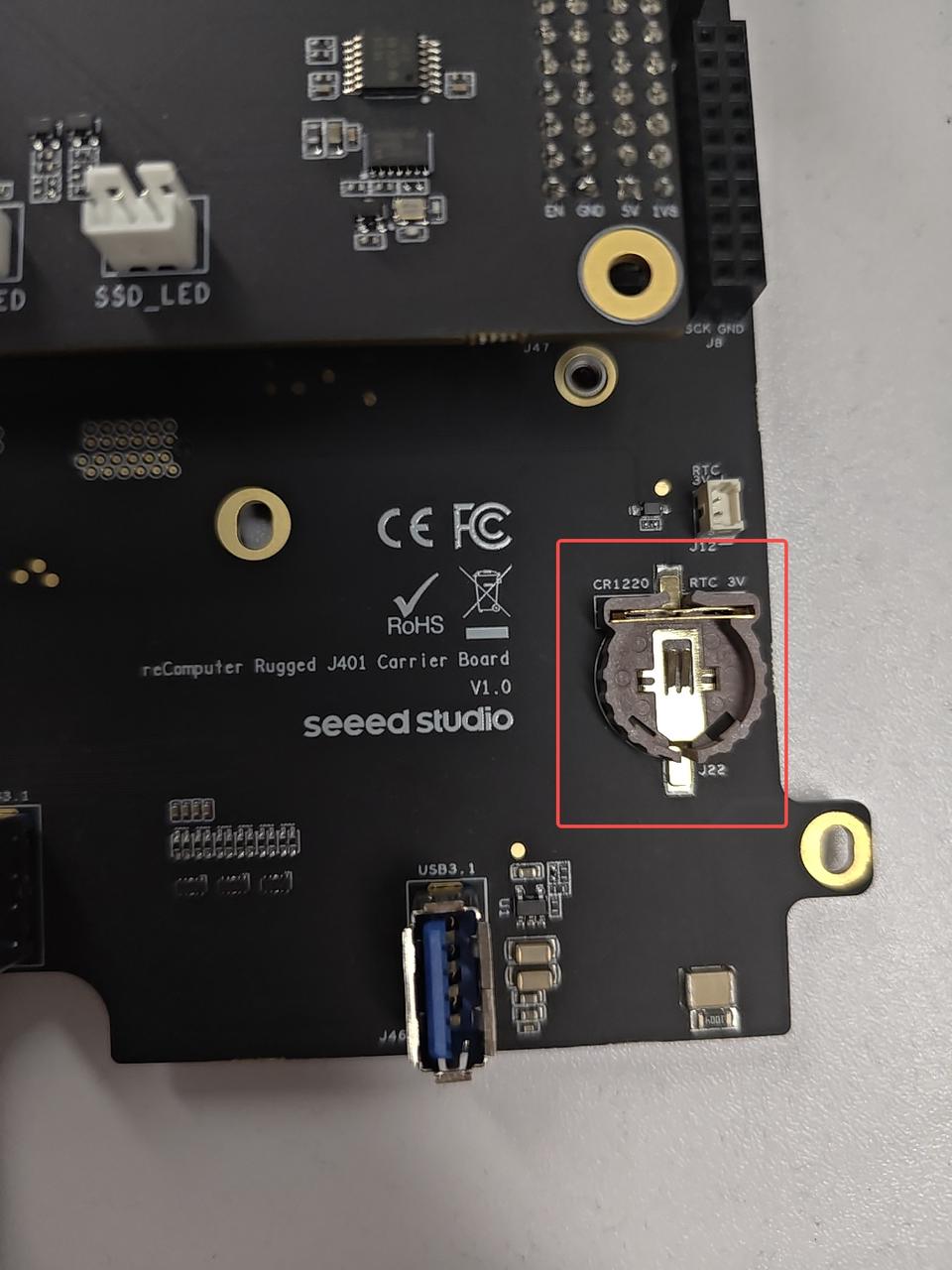
The reComputer Rugged J401 includes a hardware RTC with battery backup for accurate timekeeping. It supports CR1220 and CR1225 coin-cell batteries.
Hardware Connection
Usage Instruction
Step 1. Connect an RTC battery as mentioned above.
Step 2. Turn on reComputer Rugged J401.
Step 3. On the Ubuntu Desktop, click the drop-down menu at the top right corner, navigate to Settings > Date & Time, connect to a network via an Ethernet cable and select Automatic Date & Time to obtain the date/ time automatically.
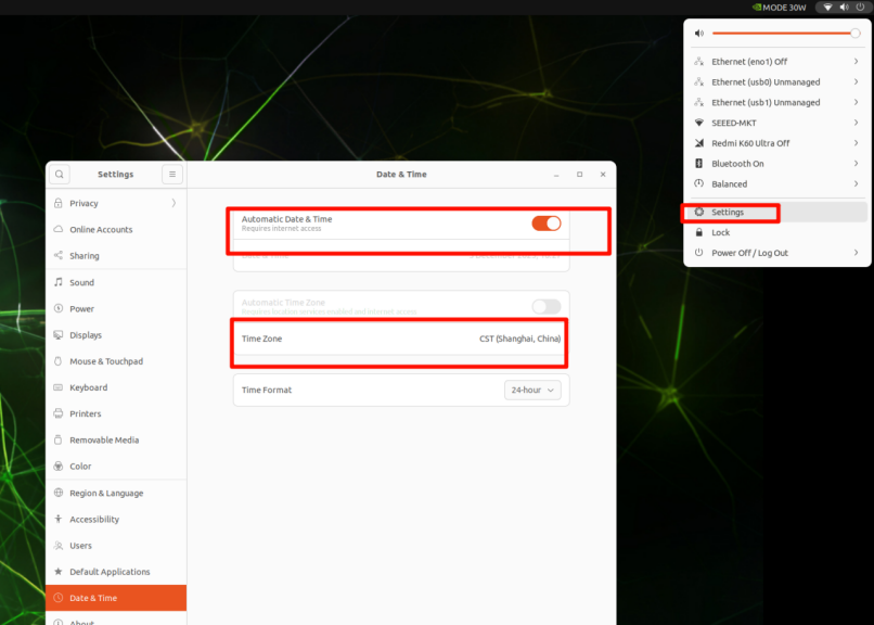
If you have not connected to internet via Ethernet, you can manually set the date/ time here.
Step 4. Open a terminal window, and execute the below command to check the hardware clock time:
cat /sys/devices/platform/bpmp/bpmp:i2c/i2c-4/4-003c/nvvrs-pseq-rtc/rtc/rtc0/time
Step 5. Disconnect the network connection and reboot the device. You will find that the system time has lost power but still functions normally.

CAN
The NVIDIA Jetson Orin Nano/NX module provides only one native CAN controller (Controller Area Network (CAN) — NVIDIA Jetson Linux Developer Guide). To obtain a second CAN interface, an external CAN controller such as the MCP2518FDT-E is required. To bring up the second CAN port, load the driver with sudo modprobe mttcan.
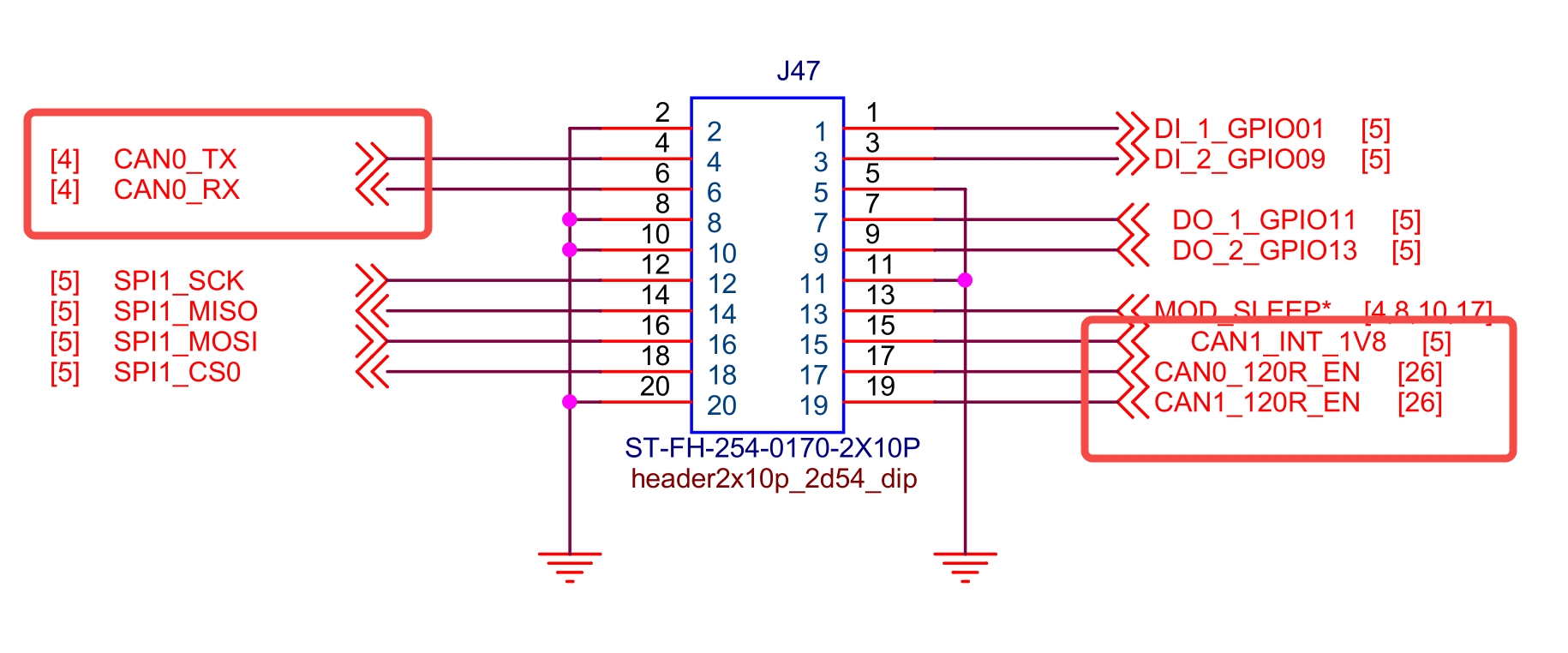
Usage Instruction
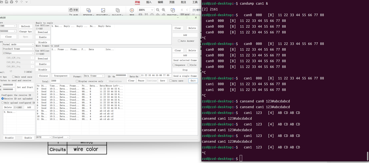
USB-CAN Test
Use a USB-CAN adapter to verify CAN communication as follows.
USB-CAN adapters usually include a built-in termination resistor.
- When
CAN0_120R_EN_3V3=1, the onboard 120 Ω termination resistor of CAN0 is disconnected. - When
CAN0_120R_EN_3V3=0, the onboard 120 Ω termination resistor of CAN0 is connected.
The same logic applies to the CAN1 termination control pin.
Load the Driver and Configure the Interface
# Load the driver to bring up the second CAN port
sudo modprobe mttcan
sudo ip link set can0 type can bitrate 125000
sudo ip link set can0 up

# Disconnect the onboard 120 Ω termination resistors
# because the USB-CAN adapter already provides termination
sudo gpioset -m wait gpiochip2 2=1 3=1
Monitor and Send Data
# Monitor data
candump can0 &
candump can1 &

# Send data
cansend can0 123#abcdabcd
CAN0 Receive and Transmit:
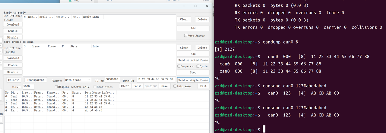
CAN1 Transmit:
CAN Loopback Test
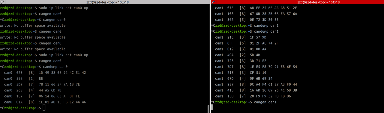
You can also connect CAN0 and CAN1 together for a board-level loopback test. Physically short the two CAN buses (CAN0_H to CAN1_H, and CAN0_L to CAN1_L), enable the onboard 120 Ω termination resistors on both sides, and then verify bidirectional communication between the two interfaces.
Open three terminals and run the following commands.
Window 1: configure and test CAN0
sudo modprobe mttcan
sudo ip link set can0 down
sudo ip link set can0 type can bitrate 250000
sudo ip link set can0 up

# Send frames from can0
cangen can0

# Receive frames on can0
candump can0
Window 2: configure and test CAN1
sudo modprobe mttcan
sudo ip link set can1 down
sudo ip link set can1 type can bitrate 250000
sudo ip link set can1 up

# Send frames from can1
cangen can1

# Receive frames on can1
candump can1
Window 3: enable termination resistors and check link counters
# Enable the onboard 120 Ω termination resistors on both CAN ports
gpioset -m wait gpiochip2 2=0 3=0

# Check low-level TX/RX counters
ip -d -s link show can0
ip -d -s link show can1
If the wiring and termination are correct, frames generated on one interface should be received on the other interface, and the TX/RX counters should increase accordingly.
DI/DO
The DI/DO interfaces of reComputer Rugged J401 are integrated on the J47 2x10P connector, sharing the interface with CAN interfaces. They support 2-channel digital input and 2-channel digital output, featuring stable signal transmission and industrial-grade voltage adaptation, suitable for connecting digital sensors, relays, and other peripheral devices.
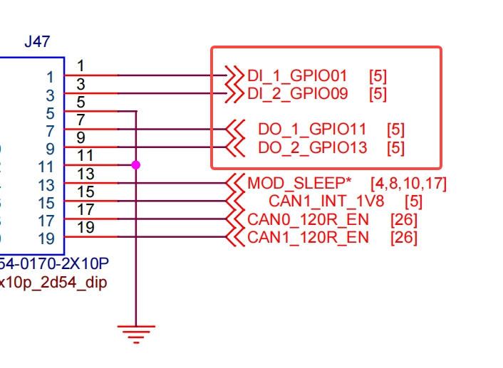
Hardware Connection
The corresponding DI/DO pins on the M12 interface are shown in the figure below.
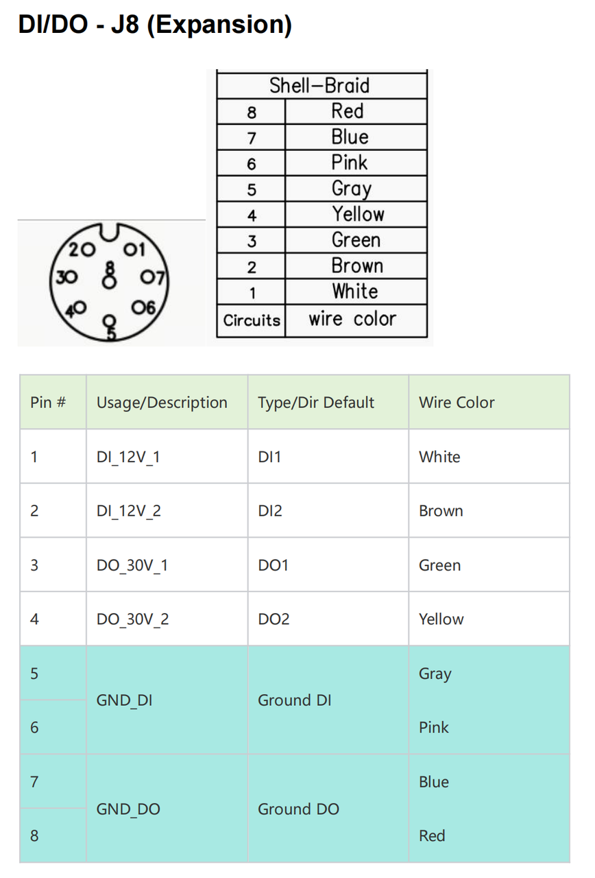
Digital Input (DI) /Digital Output(DO) Channels
Usage instruction
Digital Output (DO) Operation
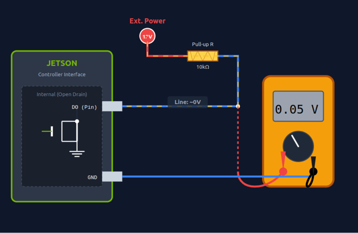
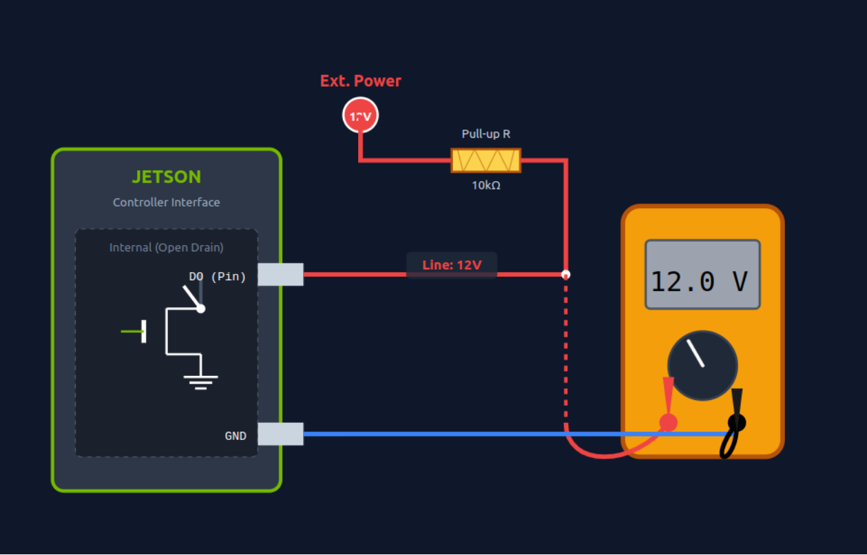
The DO interfaces adopt open-drain output. You can set the output level (high/low) via commands to control peripherals such as relays and LEDs.
Run the following command to enable the DO channel (output 12V, powered by the external pull-up resistor and 12V power supply):
# Enable DO_30V_1 (gpiochip0 106)
sudo gpioset --mode=wait 0 106=1

# Enable DO_30V_2 (gpiochip0 43)
sudo gpioset --mode=wait 0 43=1
Run the following command to disable the DO channel (output ~0V):
# Disable DO_30V_1 (gpiochip0 106)
sudo gpioset --mode=wait 0 106=0

# Disable DO_30V_2 (gpiochip0 43)
sudo gpioset --mode=wait 0 43=0
DO Before Pulling High:
DO After Pulling High:
Digital Input (DI) Operation
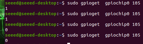
Use the gpioget command to read the input level of the DI channel (return value 1 = high level, 0 = low level) and obtain the status of peripheral devices.
# Read DI_12V_1 (gpiochip0 105) status
gpioget gpiochip0 105

# Read DI_12V_2 (gpiochip0 144) status
gpioget gpiochip0 144
UART
The reComputer Rugged J401 is equipped with an independent UART interface (UART1) that support RS232, RS422, and RS485 communication modes, featuring stable signal transmission and wide compatibility with peripheral devices.
Hardware Connection
UART Interface Channels
Switch between RS232, RS485, and RS422 modes by toggling the SW3 switch.
Note: When the switch is pressed down (ON), the bit is 0; When not pressed, the bit is 1
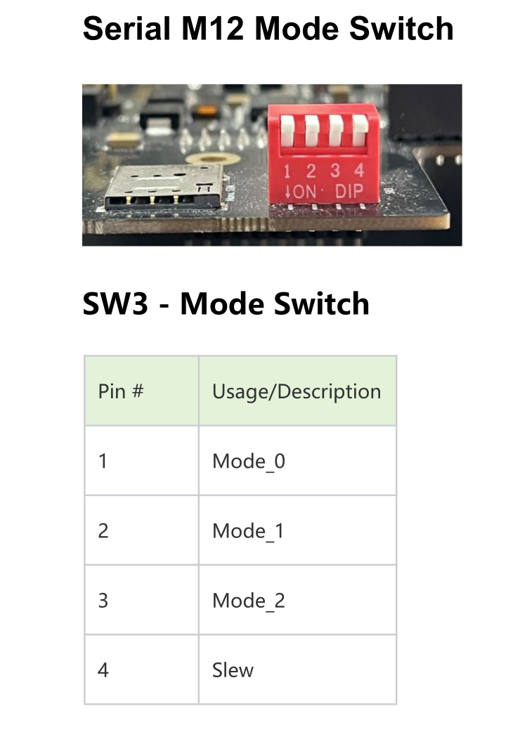
| Mode_0 | Mode_1 | Mode_2 | Mode | Status |
|---|---|---|---|---|
| 0 | 0 | 0 | RS-422 Full Duplex | 1T/1R RS-422 |
| 0 | 0 | 1 | Pure RS-232 | 3T/5R RS-232 |
| 0 | 1 | 0 | RS-485 Half Duplex | 1T/1R RS-485, TX ENABLE Low Active |
| 0 | 1 | 1 | RS-485 Half Duplex | 1T/1R RS-485, TX ENABLE High Active |
| 1 | 0 | 0 | RS-422 Full Duplex | RS-422 with termination resistor |
| 1 | 0 | 1 | RS-232 | 1T/1R RS-232 co-exists with RS485 application without the need for the bus switch bus (for special usage) |
| 1 | 1 | 0 | RS-485 | 1T/1R RS-485 with termination resistor, TX ENABLE Low Active |
| 1 | 1 | 1 | Shutdown | All I/O pins are high impedance |
SPI
Hardware Connection
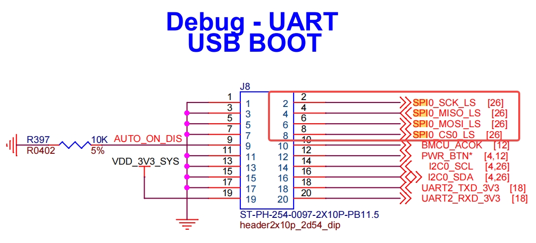
Usage Instruction
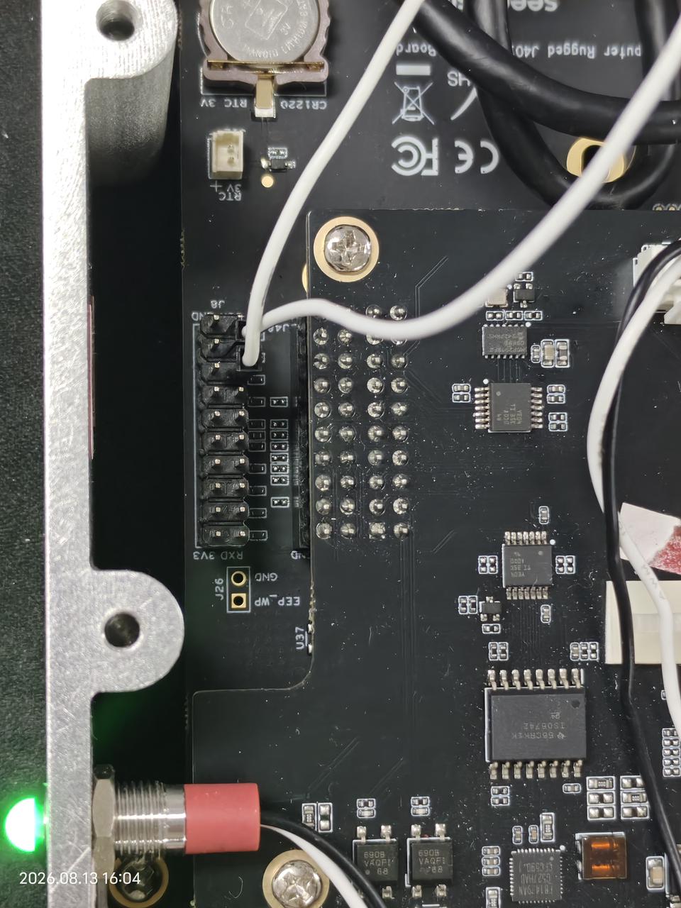
Use Dupont wires to connect the core pins of the target SPI channel (take /dev/spidev0.0 as an example): Connect the MOSI pin to its MISO pin (realize data loopback transmission/reception).
The wiring diagram is as follows:
Step 1: Load SPI Kernel Module (Prerequisite)
Before operating the SPI interface, ensure the spidev kernel module is loaded (the default system may preload it, but it is recommended to verify manually):
sudo modprobe spidev
If the command is executed without error prompts, it means the module is loaded successfully; if the module is already loaded, the command will not return any information, which is a normal phenomenon.
Step 2: View SPI Device Nodes
Enter the following command in the terminal to view the device name mapped by the SPI interface of reComputer Rugged J401:
ls /dev/spidev*
If no device node is displayed, it means the spidev module is not loaded successfully. Re-run sudo modprobe spidev and check the system log for troubleshooting.
Step 3: Obtain and Compile the SPI Test Code
Pull the spidev-test test code from GitHub and compile it:
git clone https://github.com/rm-hull/spidev-test
cd spidev-test
gcc spidev_test.c -o spidev_test
Step 4: Run the SPI Test Program
Enter the following command in the terminal to run the SPI test program (take /dev/spidev2.0 as an example):
sudo ./spidev_test -v -D /dev/spidev0.0 -s 100000 -p "Hello SPI"
Step 5: Verify the Test Result
After running the test command, you can observe the data transmission and reception status of the SPI0.0 interface in the terminal. The core output is as follows:
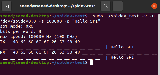
Key judgment standard: The TX (transmitted) data is consistent with the RX (received) data, indicating that the SPI loopback test is successful, and the SPI interface function is normal.
I2C
The Rugged J401 provides an I2C interface via the J8 2x10 Pin connector, enabling easy connection of sensors and peripherals for system expansion.
Hardware Connection
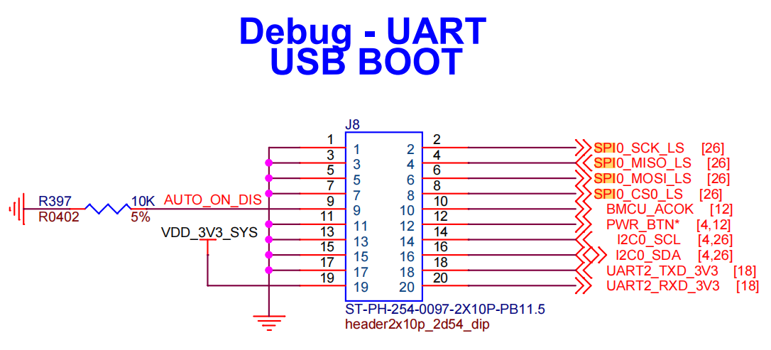
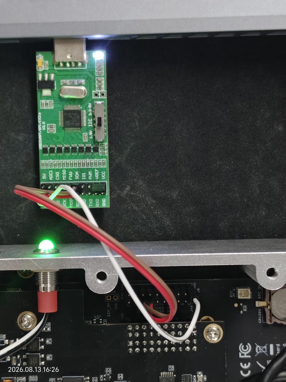
Connect your I2C device to the I2C interface on the carrier board:
-
Ground -> Ground (Pin 1)
-
SDA -> SDA (Pin 16)
-
SCL -> SCL (Pin 14)
-
VCC -> 3V3 (Pin 20)
Usage Instruction
Step 1. Install the I2C testing tools:
sudo apt update
sudo apt-get install i2c-tools
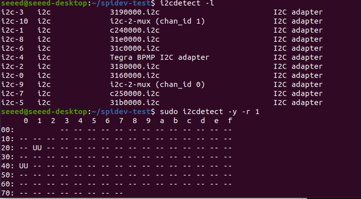
Step 2. View the I2C bus mappings:
i2cdetect -l
Step 3. Scan for devices on the I2C bus:
sudo i2cdetect -y -r 1
Resources
- reComputer Rugged J40 Datasheet
- Carrier Board Schematic
- PSE Board Schematic
- 3D File
- Linux_for_Tegra Source Code
- NVIDIA Jetson Devices Comparison
Tech Support & Product Discussion
Thank you for choosing our products! We are here to provide you with different support to ensure that your experience with our products is as smooth as possible.