Flash JetPack and Interfaces Usage | reComputer Classic J501
The reComputer Classic J501 is a high-performance, compact edge AI computer built around the NVIDIA® Jetson AGX Orin™ module (32GB/64GB), delivering up to 275 TOPS of AI performance as a drop-in replacement for the NVIDIA Jetson AGX Orin Developer Kit. It features 1x 10GbE Ethernet, 4x USB 3.2 Type-A ports, M.2 Key M (NVMe Gen4) and Key E (WiFi/BT) slots, a PCIe expansion slot, a 40-pin expansion header, and 8-lane MIPI CSI camera expansion, providing edge-side inference capabilities for workloads such as large model deployment, Vision-Language Navigation (VLN), and Vision-Language Action (VLA).
The product supports JetPack 7.2 (compatible with JetPack 6.2), supports flashing the official NVIDIA BSP and system updates via sudo apt upgrade, and is compatible with toolchains and frameworks including CUDA, TensorRT, DeepStream, Isaac ROS, PyTorch, and ROS 2/1, accelerating the development of edge AI systems such as autonomous robots, intelligent vision, and multi-sensor fusion.
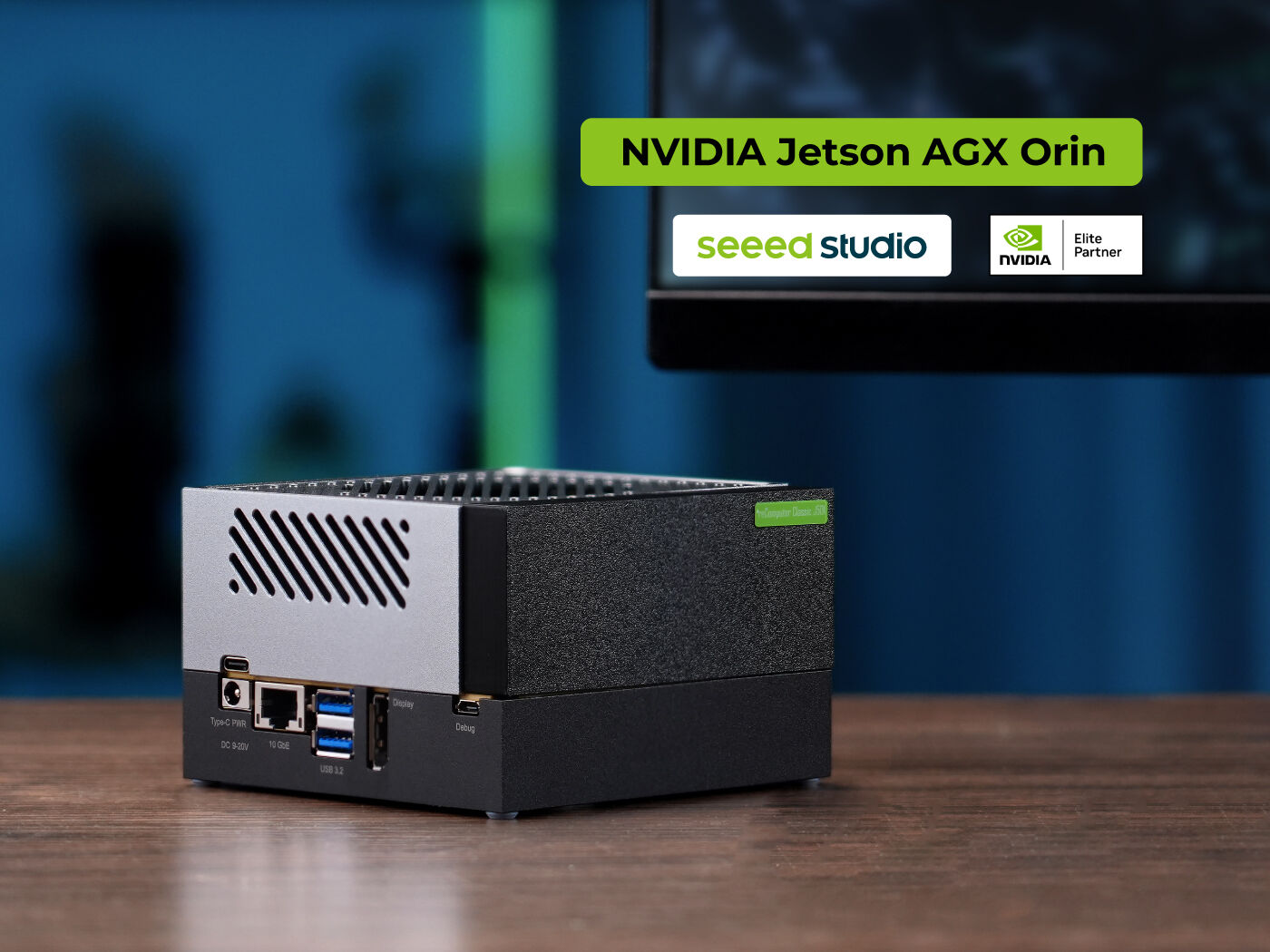
Key Features
- High-Performance AI: Equipped with the Jetson AGX Orin 32/64GB module, Ampere architecture GPU + NVDLA v2.0, up to 275 TOPS (INT8), targeting large language model deployment and Embodied AI applications
- Fully Compatible with the NVIDIA Jetson Ecosystem: Supports flashing the official NVIDIA BSP,
sudo apt upgradesystem updates, and environment setup via SDK Manager; CUDA / TensorRT / DeepStream work out of the box - Rich Connectivity: M.2 Key M (NVMe Gen4) + M.2 Key E (WiFi/BT); 1x 10GbE; 4x USB 3.2 Type-A; 2x USB Type-C (Power / Recovery)
- Full-Featured Expansion: PCIe slot (x8 electrical); 40-pin header (I2C, I2S, SPI, UART, GPIO, CAN, PWM); 8x CSI camera BTB connectors
- Robotics Ready: Supports ROS 2/1 and Isaac ROS; native CAN0/CAN1; optimized for AMR and automation scenarios
- User-Friendly Design: 19V adapter + DC 9–20V wide-range input; 0~40°C operating temperature; auto power-on (short pins 5-6 on the Automation Header)
Specifications
Jetson AGX Orin System on Module
| Item | reComputer Classic J501 (32G / J5011) | reComputer Classic J501 (64G / J5012) |
|---|---|---|
| Module | NVIDIA Jetson AGX Orin 32GB | NVIDIA Jetson AGX Orin 64GB |
| AI Performance | 200 TOPS (INT8) | 275 TOPS (INT8) |
| GPU | 1792-core NVIDIA Ampere, 56 Tensor Cores | 2048-core NVIDIA Ampere, 64 Tensor Cores |
| CPU | 8-core Arm Cortex-A78AE, 2MB L2 + 4MB L3 | 12-core Arm Cortex-A78AE, 3MB L2 + 6MB L3 |
| Memory | 32GB 256-bit LPDDR5 @ 204.8 GB/s | 64GB 256-bit LPDDR5 @ 204.8 GB/s |
| Video Encode (H.265) | 1×4K60 | 3×4K30 | 6×1080p60 | 12×1080p30 | 2×4K60 | 4×4K30 | 8×1080p60 | 16×1080p30 |
| Video Decode (H.265) | 1×8K30 | 2×4K60 | 4×4K30 | 9×1080p60 | 18×1080p30 | 1×8K30 | 3×4K60 | 7×4K30 | 11×1080p60 | 22×1080p30 |
| DL / Vision Accelerator | 2× NVDLA v2.0 / PVA v2.0 | 2× NVDLA v2.0 / PVA v2.0 |
| Onboard Storage | 64GB eMMC 5.1 | 64GB eMMC 5.1 |
| Power | 15W – 40W | 15W – 60W |
Carrier Board Specifications
| Item | Specification |
|---|---|
| Mechanical | 110mm × 110mm × 73mm |
| Display | 1× DP (DP→HDMI cable included) |
| Networking | 1× RJ45 10GbE (J17) |
| M.2 | 1× M.2 Key M (J4, NVMe 2280, Gen4, 128G SSD included); 1× M.2 Key E (J5, 2230 WiFi/BT, module included) |
| USB | 4× USB 3.2 Type-A (J24/J33); 1× USB 3.0 Type-C (Power); 1× USB 3.0 Type-C (Recovery); 1× Micro USB (J26, Debug) |
| PCIe | 1× PCIe slot (J6, UPHY block1 ×8, controller #5) |
| Expansion IO | 40-pin header (J30: I2C, I2S, SPI, UART, GPIO, CAN, PWM) |
| Camera | BTB camera connector (J509, CSI0–CSI7, 8×2-lane) |
| Fan | 1× 4-pin 5V PWM fan connector (J9, PWM + TACH) |
| Button / LED | 1× Recovery + 1× RST + 1× Power; 1× PWR/ACT green LED |
| RTC | 1× RTC 2-pin header (J13) |
| Others | Audio panel header (J511); Automation Header (J42); JTAG header (J502) |
| Power Input | DC Jack, DC 9–20V (19V adapter included) |
| Software | JetPack 7.2 (compatible with JetPack 6.2) |
| Operating Temperature | 0~40°C |
Hardware Overview
Side View 1 — Buttons / Power / Networking / Display:
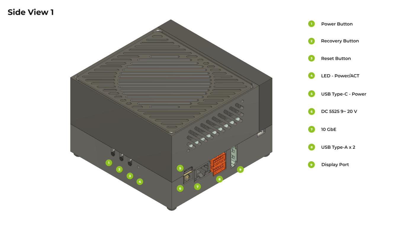
- Power Button 2. Recovery Button 3. Reset Button 4. LED - Power/ACT 5. USB Type-C - Power 6. DC 5525 9~20V (DC power jack) 7. 10 GbE (10 Gigabit Ethernet port) 8. USB Type-A × 2 9. Display Port
Side View 2 — Expansion Interfaces:
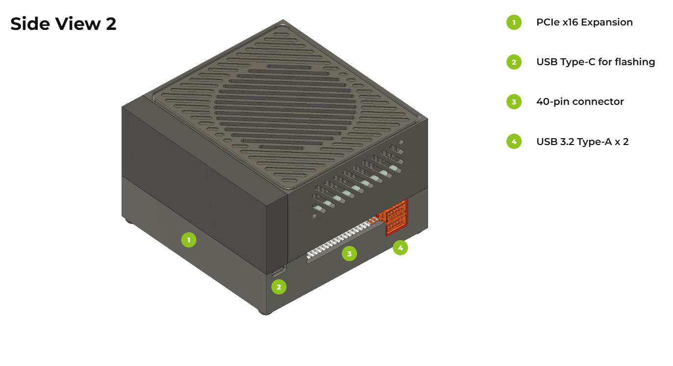
- PCIe x16 Expansion 2. USB Type-C for flashing 3. 40-pin connector (40-pin expansion header) 4. USB 3.2 Type-A × 2
Bottom View — Internal Carrier Board Interfaces:
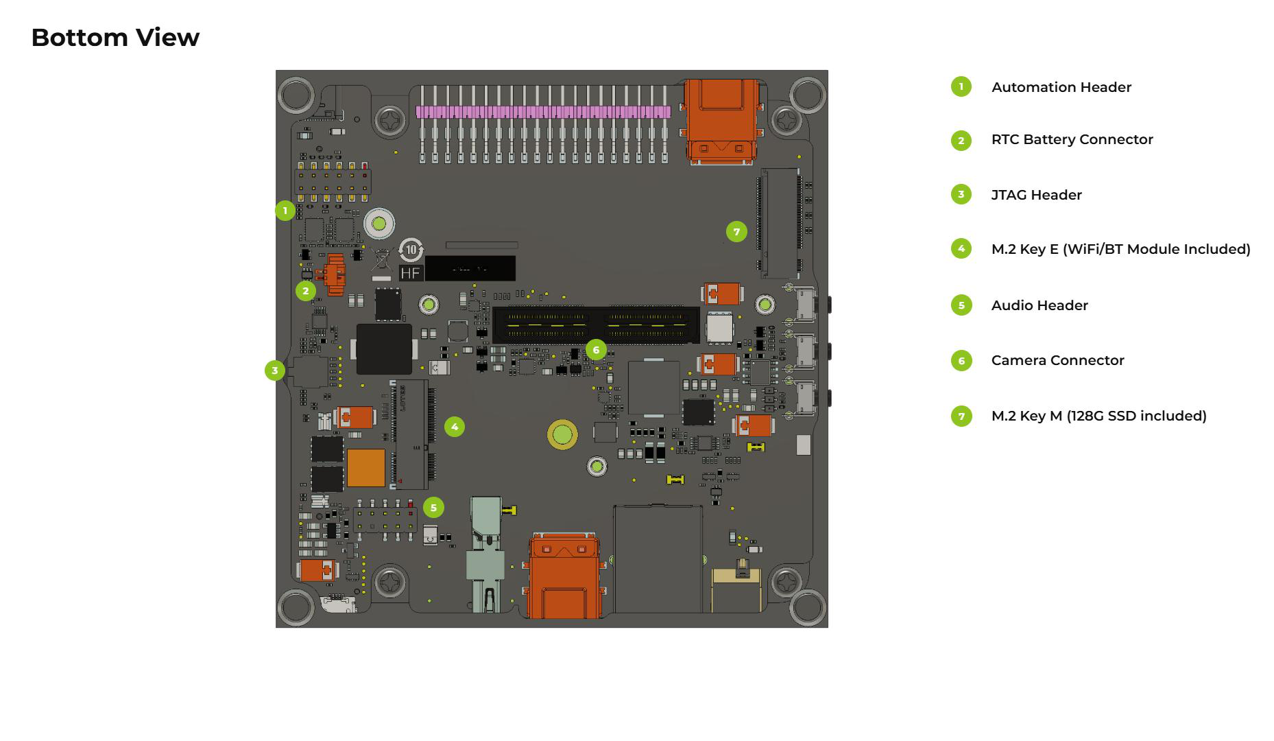
- Automation Header (J42) 2. RTC Battery Connector (J13) 3. JTAG Header (J502) 4. M.2 Key E (WiFi/BT module included) 5. Audio Header (J511) 6. Camera Connector (J509) 7. M.2 Key M (128G SSD included)
📦 Flashing the JetPack Operating System
Supported Modules
Prerequisites
- Ubuntu host PC
- reComputer Classic J501
- USB Type-C data transmission cable
- 19V power adapter
We recommend that you use physical Ubuntu host devices instead of virtual machines. Please refer to the table below to prepare the host machine.
| JetPack Version | Ubuntu Version (Host Computer) | ||
| 20.04 | 22.04 | 24.04 | |
| JetPack 7.2 | ✅ | ✅ | ✅ |
Note: For JetPack 7.2, Ubuntu 24.04 is supported for flashing and target-side component installation only. Use Ubuntu 20.04 or 22.04 if you need host development components.
Preparing the JetPack Image
Here, we need to download the system image to our Ubuntu PC corresponding to the Jetson module we are using:
| JetPack Version | Jetson Module | Download Link | SHA256 |
|---|---|---|---|
| 7.2 | AGX Orin 64GB | Download | 07bb83b8b0fced67a71126ada26076a0 76bdefee394d0647429ef9c15bab0f6b |
| AGX Orin 32GB | Download | 55e2acfbec97313dbacb04c80c668442 2e169c1e5299228d424f8807bd7be4bd |
The Classic J501 does not have a GMSL interface. The flashing example in this article is based on the 64GB version. The image file name is in the form mfi_seeed-agx-orin-64g-<JetPack version>-<L4T version>-<date>.tar.gz, and after extraction you get a directory with the same name (the example below uses mfi_seeed-agx-orin-64g-7.2.0-39.2.0-2026-08-04; please refer to the actual downloaded file name).
The JetPack image files are large and may take around 60 minutes to download. Please wait for the download to complete.
To verify the integrity of the downloaded firmware, you can compare the SHA256 hash value.
On an Ubuntu host machine, open the terminal and run the command sha256sum <File> to obtain the SHA256 hash value of the downloaded file. If the resulting hash matches the SHA256 hash provided in the wiki, it confirms that the firmware you downloaded is complete and intact.

⚙️ All .dts files and other source code for SEEED Jetson carrier boards can be downloaded from Linux_for_Tegra
Entering Force Recovery Mode
Step-by-step instructions
Before we can move on to the installation steps, we need to make sure that the board is in force recovery mode.
📌 Key hardware locations (see also "Hardware Overview" in this article):
| Component | Location | Description |
|---|---|---|
| Recovery Button | Side View 1, label #2 | 1× Recovery Button on the carrier board (same side as Power and Reset) |
| Recovery USB-C Port | Side View 2, label #2 (USB Type-C for flashing) | Dedicated USB Type-C port for firmware flashing, labeled 1× USB 3.0 Type-C (Recovery) in the datasheet, used for flashing |
| Other USB Ports | Type-C (Power) / Micro-B (Debug) / 4× USB 3.2 Type-A | Do not connect to the wrong Recovery port |
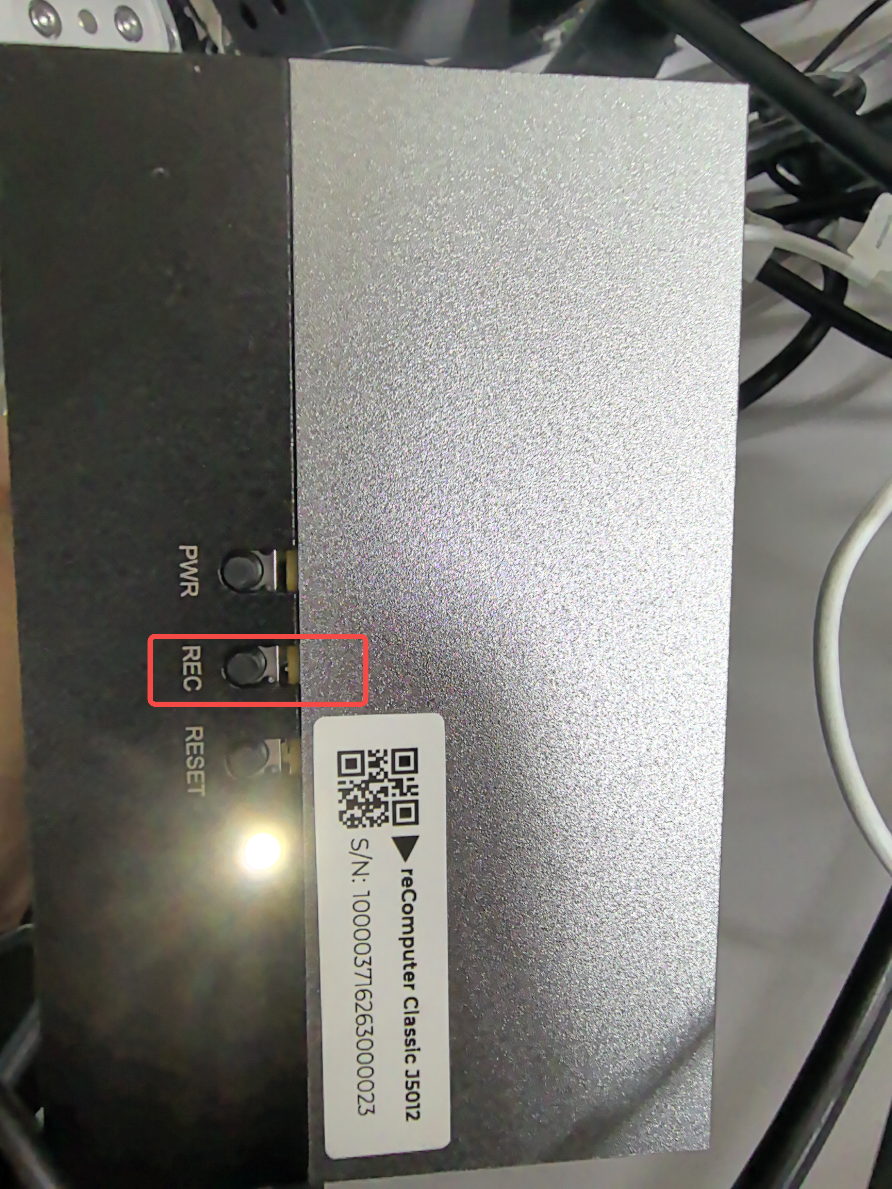
Step 1. Connect the USB Type-C for flashing port on the carrier board (Side View 2, label #2) to the Ubuntu host PC using a USB Type-C data cable.
Step 2. Press the recovery button (Side View 1, label #2) and keep holding it.
Step 3. Connect the power supply (DC 5525, 9–20V / 19V adapter).
Step 4. Release the recovery button.
Step 5. On the Linux host PC, open a Terminal window and enter the command lsusb. If the returned content has one of the following outputs according to the Jetson SoM you use, then the board is in force recovery mode.
- For AGX Orin 64GB: 0955:7023 NVidia Corp
- For AGX Orin 32GB: 0955:7223 NVidia Corp
The image below is an example for the AGX Orin 64GB:

Flashing to the Jetson
Step 1: Extract the downloaded image file (taking the 64GB version as an example):
cd <path-to-image>
sudo tar xpf mfi_xxxx.tar.gz
# For JetPack 7.2 example: sudo tar xpf mfi_seeed-agx-orin-64g-7.2.0-39.2.0-2026-08-04.tar.gz

Step 2: Execute the following command to flash the JetPack system to the NVMe SSD:
cd mfi_xxxx
# For example: cd mfi_seeed-agx-orin-64g-7.2.0-39.2.0-2026-08-04
sudo ./tools/kernel_flash/l4t_initrd_flash.sh --flash-only --massflash 1 --network usb0 --showlogs
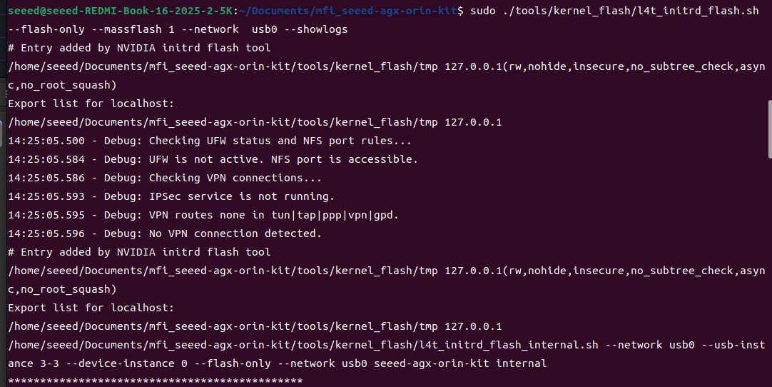
If the flashing process is successful, you will see the following output (Successfully flashed the QSPI / Successfully flashed the eMMC / Flashing success):
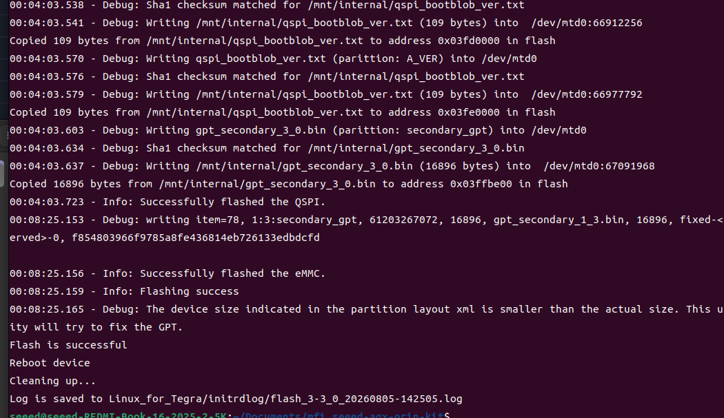
The flash command may run for 2-10 minutes.
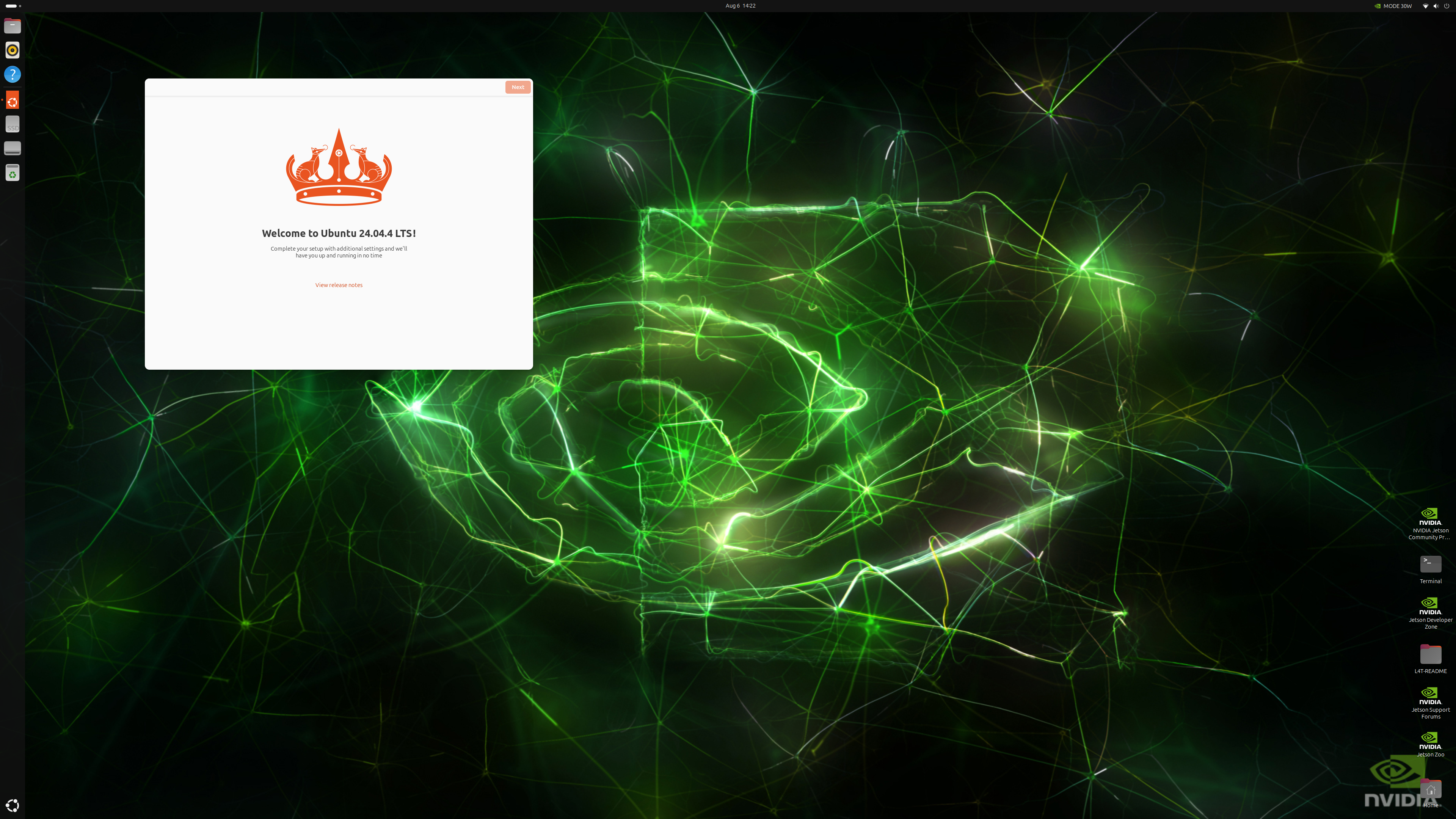
Step 3: Connect a display using a DP cable (or the included DP→HDMI cable), power on the device, and complete the initial system configuration (language, username, network, etc.).
🔌 Interface Usage
The following will introduce the various interfaces on the reComputer Classic J501 board and how to use them.
M.2 Key M
The J501 includes 1x M.2 Key M slot (J4), supporting PCIe Gen4 x4 NVMe SSDs (2280 size), with a 128G SSD included in the package.
Supported SSD are as follows
- 128GB NVMe M.2 PCle Gen3x4 2280 Internal SSD
- 256GB NVMe M.2 PCle Gen3x4 2280 Internal SSD
- 512GB NVMe M.2 PCle Gen3x4 2280 Internal SSD
- 1TB NVMe M.2 PCle Gen3x4 2280 Internal SSD
- 2TB NVMe M.2 PCle Gen3x4 2280 Internal SSD
Hardware Connection
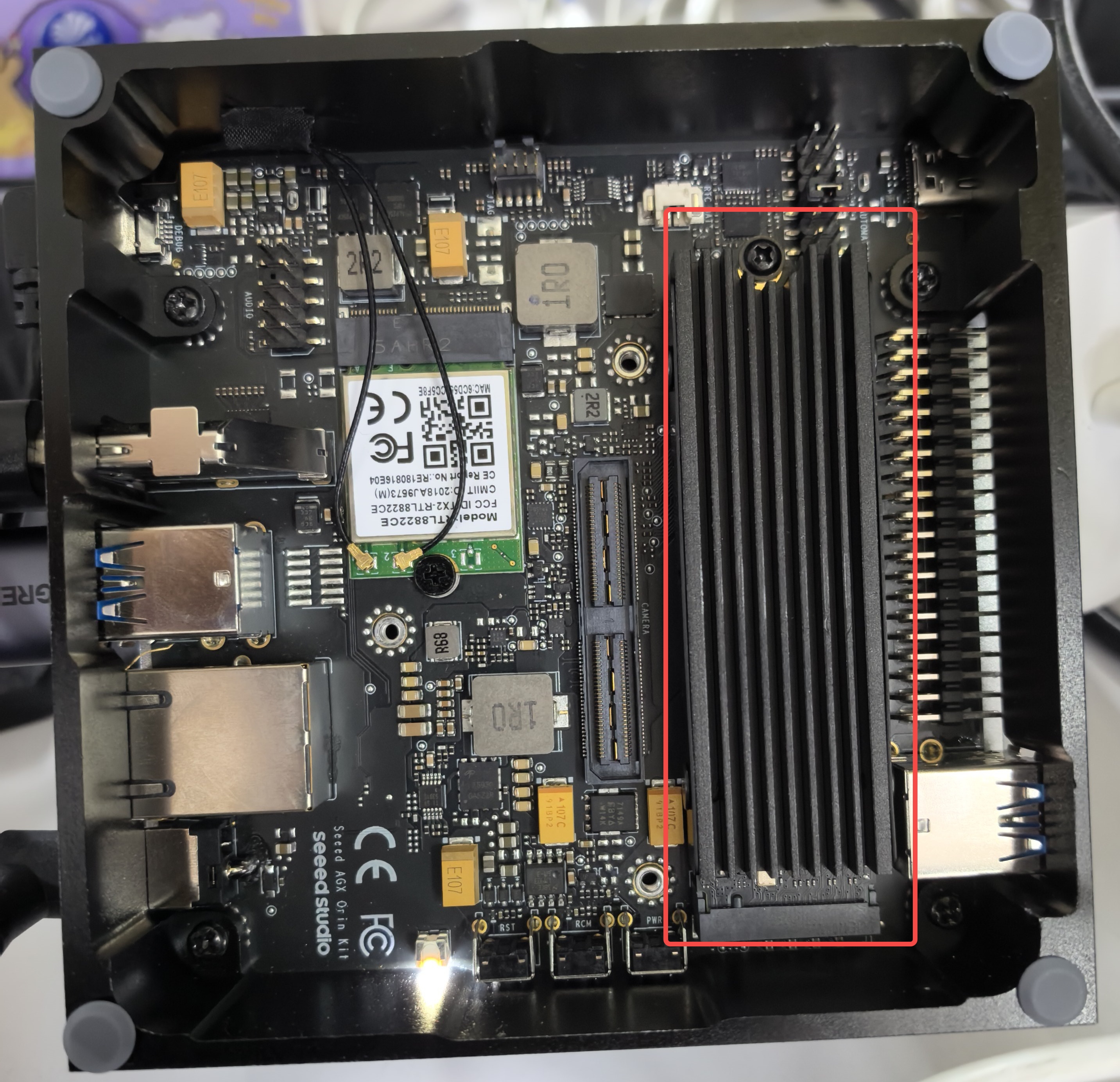
The M.2 Key M location is shown in the bottom view of the "Hardware Overview", label 7. After removing the enclosure screws, insert the NVMe SSD into the slot and secure it with the screw.
Usage Instruction
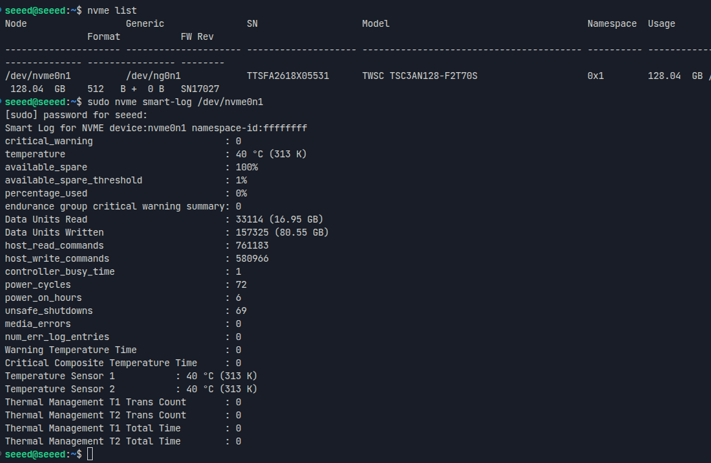
Open the terminal in the Jetson device and enter the following commands to test the SSD's status and read/write speed.
Step 1. Check SSD basic information:
nvme list
Step 2. Check SSD health status (SMART info):
sudo nvme smart-log /dev/nvme0n1
Step 3. Test write performance:
mkdir -p ~/ssd
dd if=/dev/zero of=~/ssd/test bs=1024M count=5 conv=fdatasync
Step 4. Test read performance (clear the page cache first to avoid reading from memory):
sudo sh -c "sync && echo 3 > /proc/sys/vm/drop_caches"
dd if=~/ssd/test of=/dev/null bs=1024M
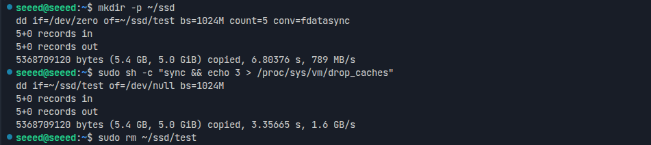
Please run the sudo rm ~/ssd/test command to delete the test file after the test is complete.
M.2 Key E (WiFi/BT)
The M.2 Key E slot (J5) supports M.2 2230 Wi-Fi / Bluetooth modules for wireless connectivity, with a WiFi/BT module included in the package.
Hardware Connection
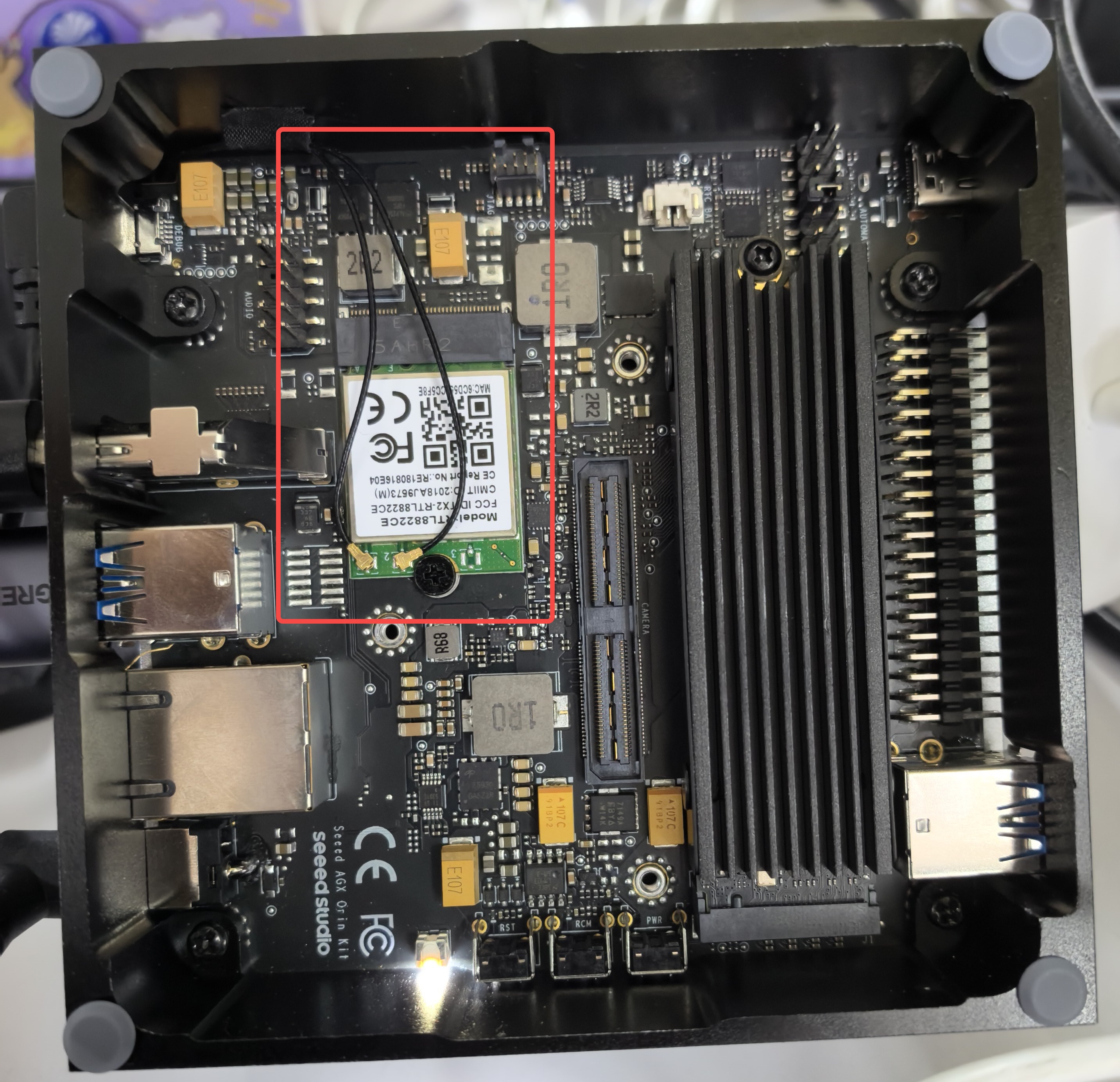
Note: Before using this interface, you must remove the enclosure screws, install the WiFi/BT module into the M.2 Key E slot (see bottom view of the "Hardware Overview", label 4), and connect the antennas.
Usage Instruction
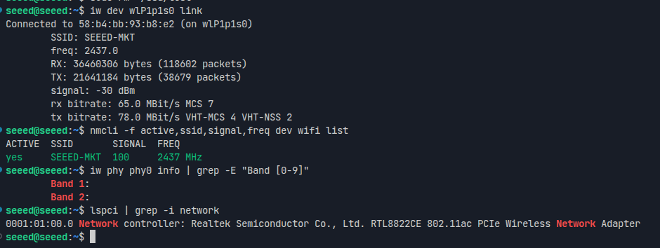
Step 1. Check WiFi module PCIe recognition:
lspci | grep -i network
Step 2. Check the current connection status:
iw dev <wlanX> link
Step 3. Scan nearby WiFi networks:
nmcli -f active,ssid,signal,freq dev wifi list
Step 4. Confirm the frequency bands supported by the module (Band 1 = 2.4GHz, Band 2 = 5GHz):
iw phy phy0 info | grep -E "Band [0-9]"
Performance Test: To test Wi-Fi performance, use the following command (replace the IP address with your test server):
# On server: iperf3 -s
# On client:
iperf3 -c your_server_ip
Bluetooth functionality is available via the M.2 Key E slot (scan/pair with bluetoothctl).
Ethernet
The Classic J501 provides 1x RJ45 10GbE port (J17), supporting 10 Gigabit Ethernet and backward compatible with lower speeds.
LED Indicators per port (normal working status):
- Green LED: ON indicates the link is established
- LED Blinking: indicates network activity
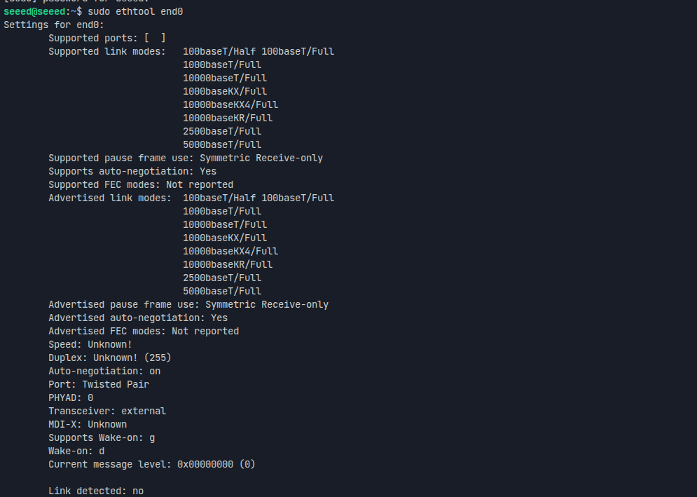
Use ethtool to verify that the PHY is working properly and view the supported speed modes (it is normal for "Link detected" to show no when no cable is connected):
sudo ip link set end0 up
sudo ethtool end0
To test the Ethernet port speed, use iperf3 as follows (an Ethernet cable connected to a peer server is required):
iperf3 -c <server_ip> -B <bind_ip>
<server_ip> is the IP address of the iperf3 server. The client will connect to this server to perform a bandwidth test.
<bind_ip> binds the specified local IP address as the source of the test traffic.
LED
The J501 is equipped with a status indicator LED:
- PWR/ACT LED: Power / system activity status (green)
USB
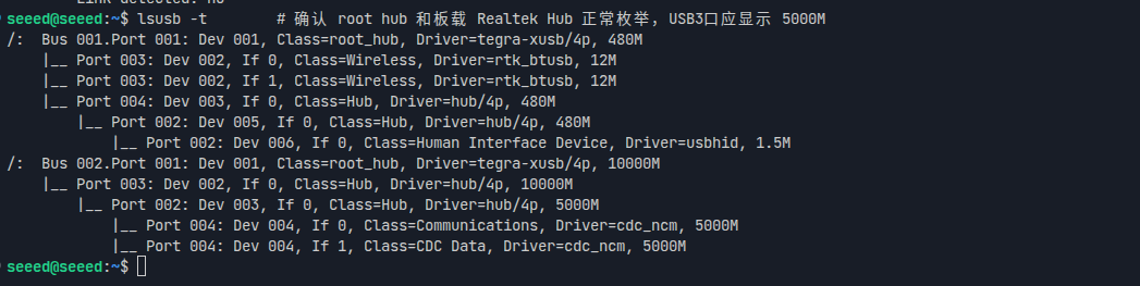
The Classic J501 provides 4x USB 3.2 Type-A ports (J24/J33, 10Gbps, host mode only, for connecting high-speed peripherals, storage devices, or cameras), 1x USB 3.0 Type-C power port, 1x USB 3.0 Type-C Recovery port (flashing port), and 1x Micro USB debug port (J26).
USB Bus Topology
Use lsusb -t to view the device tree and check the connection status and negotiated speed of each USB port and peripheral:
lsusb -t
USB-A Speed Test
Create a script to test USB device speed:
vim test_usb.sh
Paste the following content:
test_usb.sh
cat <<'EOF' | sudo tee test_usb.sh >/dev/null
#!/bin/bash
set -e

MOUNT_POINT="$1"
TEST_FILE="$MOUNT_POINT/test_usb_speed.bin"

if [ -z "$MOUNT_POINT" ]; then
  echo "Usage: $0 <mount_point>"
  echo "Example: $0 /media/seeed/USB"
  exit 1
fi

if [ ! -d "$MOUNT_POINT" ]; then
  echo "Error: $MOUNT_POINT is not a directory"
  exit 1
fi

echo "Write test..."
dd if=/dev/zero of="$TEST_FILE" bs=1M count=2048 conv=fdatasync status=progress

echo
echo "Drop caches..."
sync
echo 3 | sudo tee /proc/sys/vm/drop_caches >/dev/null

echo "Read test..."
dd if="$TEST_FILE" of=/dev/null bs=1M count=2048 status=progress

echo
echo "Cleaning up..."
rm -f "$TEST_FILE"
EOF
Make the script executable and test:
sudo chmod +x test_usb.sh
./test_usb.sh /mnt          # If your USB drive is mounted at /mnt
# Or
./test_usb.sh /media/usb    # If your USB drive is mounted at /media/usb
# Or
./test_usb.sh /path/to/your/usb/mount_point
Please confirm the actual mount point of your USB device first using the df -h or lsblk command!
Micro USB Debug Serial Port
Using this serial port and a Micro-USB cable, you can monitor the debugging information of input and output on the PC side.
Step 1. Open the serial port tool (here we use the MobaXterm tool as an example) and create a new session.
Step 2. Select the Serial tool.
Step 3. Select the corresponding serial port, set the baud rate to 115200 and click "OK".
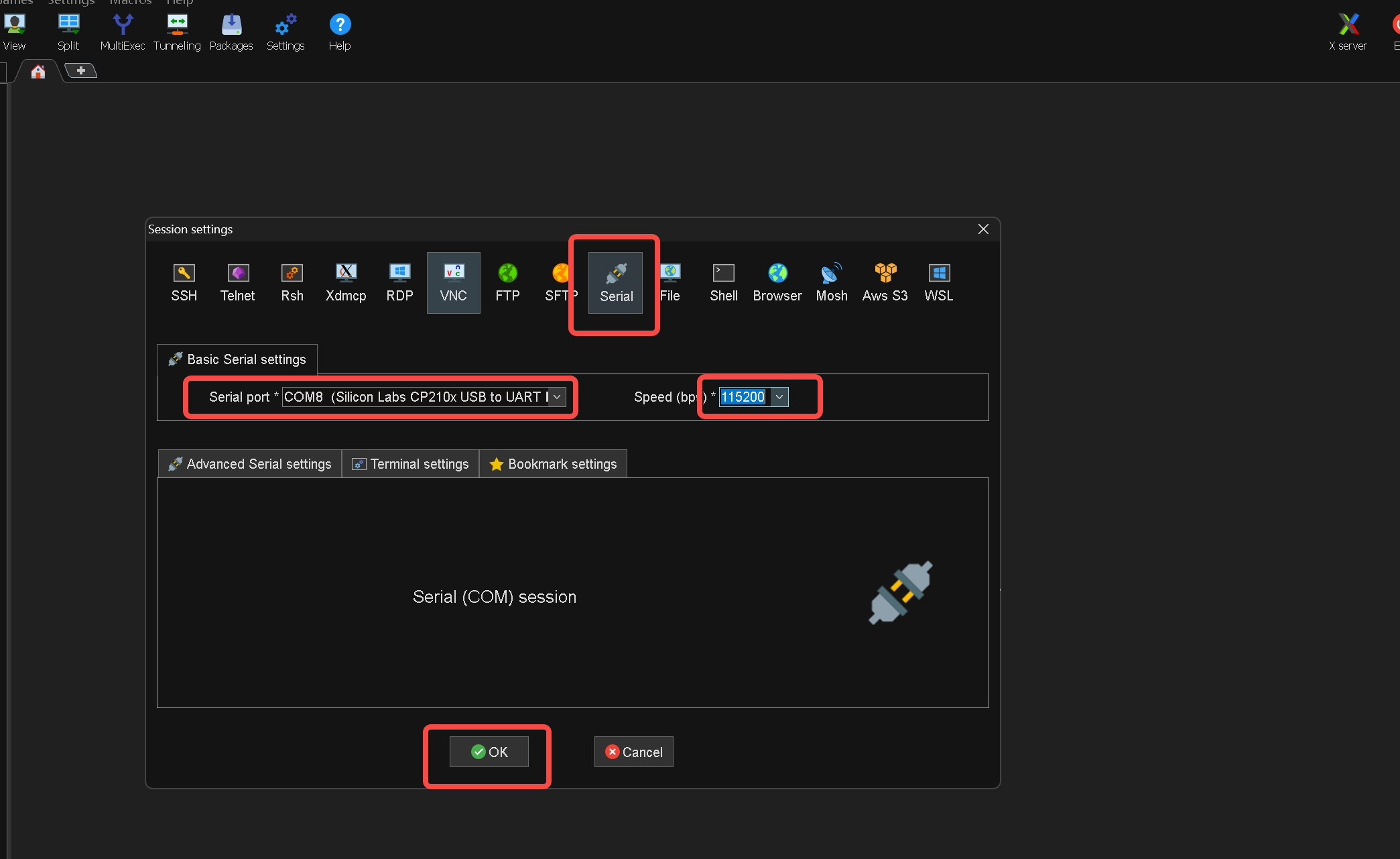
Step 4. Log in to your reComputer Classic J501 with the username and password.
Fan
The Classic J501 provides 1x 4-pin 5V PWM fan connector (J9), with the pinout defined as GND / Power / FAN_TACH (speed sensing) / FAN_PWM (speed control). The PWM control allows dynamic and precise speed adjustment based on system temperature, achieving efficient cooling while minimizing noise and power consumption.
Usage Instruction
Manual PWM Control:
# Set fan speed (0-255)
sudo -i
echo 200 > /sys/bus/platform/devices/pwm-fan/hwmon/hwmon1/pwm1
Default thermal policy is pre-configured in /etc/nvpmodel.conf. For custom profiles, refer to NVIDIA Jetson Linux Developer Guide.
Additionally, we can manually set the fan speed using the jtop tool.
You can enter the following command in the terminal to install jtop:
sudo apt update
sudo apt install python3-pip -y
sudo pip3 install jetson-stats
Then reboot your reComputer Classic J501:
sudo reboot
After installing jtop, you can launch it in the terminal:
jtop
40-Pin Expansion Header (GPIO / I2C / SPI / UART / CAN / I2S / PWM)
The 40-pin header of the Classic J501 (J30, see Side View 2 of the "Hardware Overview", label 3) is compatible with the Raspberry Pi header form factor, providing: 2x I2C (I2C2/I2C4), SPI1 (dual chip select), UART1 (TX/RX/RTS/CTS), I2S2, native CAN0/CAN1, PWM01, and multiple GPIOs.
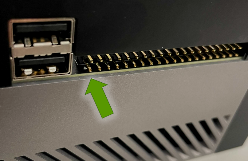
The physical location of the header is shown in the figure below (indicated by the green arrow, next to the USB Type-A ports):
The pinout is shown in the figure below:
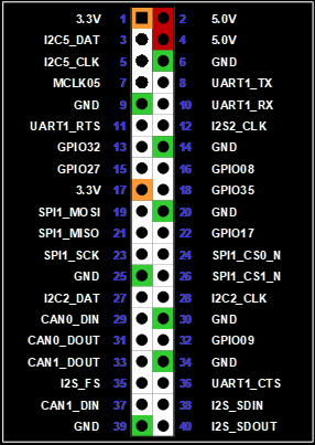
The GPIOxx labels in the figure are Raspberry Pi compatible numbers; some labels are inconsistent with the J30 pin table in the datasheet (e.g., the icons for pins 3/5 show I2C5 while the datasheet says I2C4, I2S abbreviations, etc.). The official naming follows the datasheet pin table (pins 3/5 correspond to module ball positions E60/D61 = I2C4_DAT/CLK).
GPIO Operation
Use the libgpiod tools to operate GPIOs (first query the chip and line numbers with gpioinfo):
gpioinfo
sudo gpioset --mode=wait <gpiochipX> <line>=1   # set output high
sudo gpioget <gpiochipX> <line>                 # read input
SPI Loopback Test
Step 1. Load the spidev module: sudo modprobe spidev
Step 2. Check the device nodes: ls /dev/spidev*
Step 3. Get and compile the test code:
git clone https://github.com/rm-hull/spidev-test
cd spidev-test
gcc spidev_test.c -o spidev_test
Step 4. Short the MOSI and MISO of the selected SPI (loopback) and run the test (the 40-pin SPI1 is usually /dev/spidev0.0; refer to the actual node from ls /dev/spidev*):
sudo ./spidev_test -v -D /dev/spidev0.0 -s 100000
Step 5. The loopback test is successful if the TX and RX data are consistent.
UART Test
The UART1 on the 40-pin header (pins 8/10/11/36) can be connected to a USB-to-serial adapter and tested using CuteCom:
sudo apt-get install cutecom
sudo cutecom
Serial port parameters: device /dev/ttyTHS1 (40-pin UART1, refer to the actual node), baud rate 115200, 8N1, no flow control.
CAN Communication
The 40-pin header provides CAN0 (pins 29/31) and CAN1 (pins 33/37). These 4 pins are 3.3V TTL level CAN controller signals directly connected to the AGX Orin module (CANx_DOUT = controller TX, CANx_DIN = controller RX). There is no onboard CAN transceiver on the carrier board, and there are no directly wirable CAN_H/CAN_L on the header; an external 3.3V CAN transceiver (e.g., SN65HVD230 / TCAN332, with SN65HVD230 officially recommended by NVIDIA) is required before networking.
The loopback test requires 2 transceivers: on the TTL side, connect the transceiver TXD→CANx_DOUT, RXD←CANx_DIN, VCC→3.3V (pins 1/17), GND→ground; cross-wire the bus side (CAN0_H↔CAN1_H, CAN0_L↔CAN1_L, with 120Ω termination resistors at both ends of the bus), then the loopback test can be performed:
Confirmed (based on the datasheet 40-pin pin table): the CAN pins of J30 are direct-connection signals from module ball positions (CAN0_DIN=F58, CAN0_DOUT=D59, CAN1_DOUT=H61, CAN1_DIN=B61); no onboard transceiver is marked anywhere in the datasheet, which is consistent with the NVIDIA AGX Orin DevKit 40-pin definition; NVIDIA official documentation explicitly requires an external ≥3.3V CAN transceiver.
Classic CAN mode
# Configure and bring up the interfaces (Classic CAN, 1 Mbps example)
sudo ip link set can0 down
sudo ip link set can1 down
sudo ip link set can0 type can bitrate 1000000
sudo ip link set can1 type can bitrate 1000000
sudo ip link set can0 up
sudo ip link set can1 up

# One terminal receives, the other sends
candump can1 &
cangen can0 -g 10
CAN-FD mode
sudo ip link set can0 type can bitrate 500000 dbitrate 5000000 fd on berr-reporting on restart-ms 100
sudo ip link set can0 up
Camera Connector
The Classic J501 brings out CSI0–CSI7 (8x 2-lane MIPI CSI ports) through a 120-pin BTB connector (J509, see bottom view of the "Hardware Overview", label 6), and provides camera I2C, master clock (MCLK), Powerdown/Reset, frame sync (FRSYNC), and 2.8V/1.8V/3.3V camera power, suitable for multi-camera synchronized perception solutions.
Hardware Connection
This interface is in BTB (board-to-board) form and requires a Seeed or self-developed camera adapter board/FPC cable.
Usage Instruction
Step 1. Check the device nodes: ls /dev/video*
Step 2. Preview using GStreamer (example):
gst-launch-1.0 v4l2src device=/dev/video0 ! \
video/x-raw,width=1920,height=1080,framerate=30/1 ! \
videoconvert ! xvimagesink
Audio Interface
10-pin audio panel header (J511, see bottom view of the "Hardware Overview", label 5): dual microphone inputs (IN1P/IN2P), stereo headphone output (HPO_L/HPO_R), jack/presence detection.
After connecting the audio panel board, you can select the corresponding input/output devices in the Ubuntu sound settings for recording and playback tests:
arecord -l   # list capture devices
aplay -l     # list playback devices
arecord -d 5 test.wav && aplay test.wav
Display (DP)
The Classic J501 is equipped with 1x DisplayPort interface. You can connect a display directly with a DP cable, or use the included DP→HDMI cable to connect an HDMI display, supporting desktop and multi-stream video rendering output.
PCIe Expansion Slot
The onboard PCIe slot (J6, see Side View 2 of the "Hardware Overview", label 1) is physically an x16 form factor and electrically x8 (UPHY block 1 Lane 0–7, PCIe controller #5), featuring 12V/3.3V power and full control signals (PERST#/CLKREQ#/WAKE#/presence detection), and can be used to expand network cards, capture cards, NVMe adapter cards, and more.
sudo lspci            # check whether the PCIe device is detected
sudo lspci -vvv -s <BDF>
RTC
The Classic J501 maintains timekeeping during power loss by connecting an external backup battery via the RTC 2-pin header (J13, PMIC_BBATT, see bottom view of the "Hardware Overview", label 2).
Step 1. Connect the RTC battery (mind the polarity).
Step 2. Power on the device, go to Settings > Date & Time, connect to a network and select Automatic Date & Time (or set it manually).
If you have not connected to the internet, you can manually set the date/time here.
Step 3. Open a terminal window and execute the following command to check the hardware clock time:
cat /sys/devices/platform/bpmp/bpmp\:i2c/i2c-4/4-003c/nvvrs-pseq-rtc/rtc/rtc0/time
Step 4. Disconnect the network connection and reboot the device to verify time retention.
Automation Header (Auto Power-On / Remote Power Control)
The Automation Header J42 (see bottom view of the "Hardware Overview", label 1) provides signals including FORCE_RECOVERY_N (pin 2), SYS_RESET_N (pin 3), the power button signal (pin 4), PD controller output/ACOK (pins 5/6), MODULE_SLEEP_N (pin 7), over-current indication SYSTEM_OC_N (pin 8), and Wake on LAN (pin 9, GPIO38).
Short pins 5 and 6 to enable Auto-Power-On, suitable for unattended devices.
Resources
- reComputer Classic J5011 (32GB) Product Page
- reComputer Classic J5012 (64GB) Product Page
- reComputer Classic J501 Datasheet (PDF Download)
- NVIDIA Jetson AGX Orin Module Datasheet (PDF Download)
- reComputer Classic J501 3D Model (STP Download)
- Seeed NVIDIA Jetson Product Catalog
- Source code of Seeed's L4T (Linux_for_Tegra)
- NVIDIA Jetson AGX Orin Documentation
Tech Support & Product Discussion
Thank you for choosing our products! We are here to provide you with different support to ensure that your experience with our products is as smooth as possible. We offer several communication channels to cater to different preferences and needs.