Getting started with Atom-S
Introduction
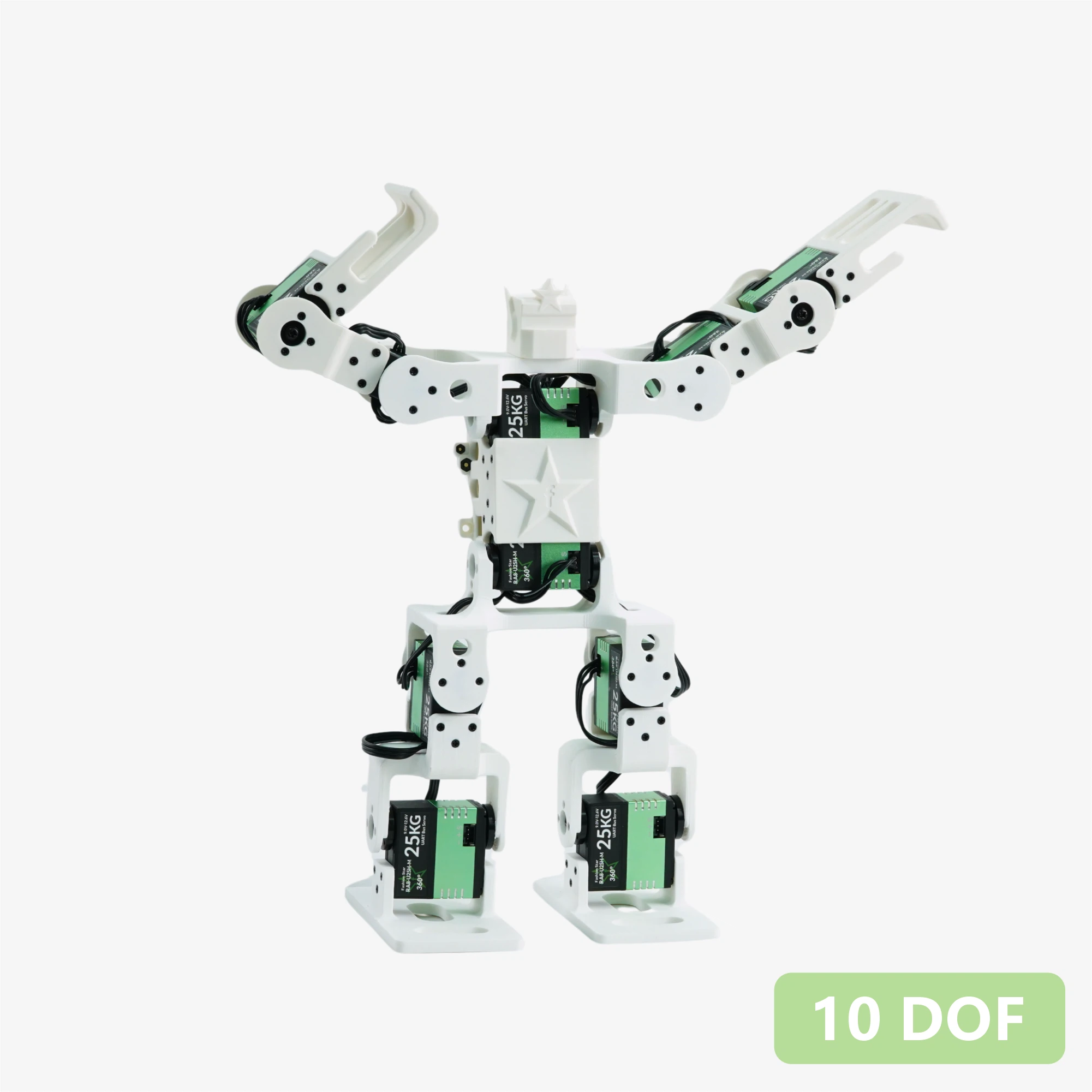
The Atom-S is a 10-DOF (Degrees of Freedom) open-source bipedal humanoid robot kit designed for developers, makers, and educational institutions. The robot is driven by ten Fashionstar RA8-U25H-M bus servos, features a fully open-source 3D-printed structure, and is equipped with a Seeed Studio XIAO ESP32-S3 main controller and Grove expansion board. It comes with complete control firmware pre-installed from the factory. Its core highlight is the installation-free web-based visual motion editor — you can debug servos in real time, record teaching motions, and export JSON directly through a browser, making it easy to replicate on platforms such as Arduino, STM32, and Raspberry Pi. The included RUC-01 adapter board provides 5 V / 3.3 V regulated power and a UART interface, supporting Bluetooth and web remote control. Ready to use out of the box, it is an ideal platform for desktop robotics development and algorithm verification.
1. Product Introduction
- DOF Layout: The robot features 10 degrees of freedom covering the arms, torso, and legs.
- Structure & Appearance: Fully 3D-printed structure with officially open-sourced STP / STL model files, facilitating part replacement, structural reinforcement, and cosmetic redesign.
- Joint Actuators: Ten Fashionstar RA8-U25H-M bus servos with bus communication for clean, simplified wiring.
- Web Motion Editor: A browser-based control panel that supports real-time servo debugging and teach-mode programming. Completed motion groups can be exported as standard
.jsonfiles for easy parsing on Arduino, STM32, and Raspberry Pi platforms. - Out-of-the-Box Ready: Ships with the Seeed Studio XIAO ESP32-S3 as the default main controller, with demonstration programs pre-flashed at the factory.
- Multi-Module Expansion: Paired with the Seeed Studio XIAO expansion board, the onboard Grove interface allows connection of Seeed Grove sensors and controllers.
- Cross-Platform Compatibility: The RUC-01 adapter board provides 5 V / 3.3 V power output and a UART interface; any controller with serial-port capability can communicate with it.
- Ecosystem Extensibility: Leveraging the Grove interfaces on the Seeed Studio XIAO expansion board, vision, environmental sensing, and other Grove ecosystem sensors and control modules can be integrated rapidly.
- Cross-Platform Compatibility: The standard RUC-01 driver adapter board provides regulated 5 V / 3.3 V output and a universal UART communication interface, making it easy to connect external Raspberry Pi, STM32, Arduino, ESP32, or PC platforms.
2. Specifications
| Parameter | Value |
|---|---|
| Degrees of Freedom (DOF) | 10 |
| Chassis | 3D Printed |
| Servos | RA8-U25H-M Bus Servo |
| Servo Power / Interface Board | RUC-01, providing 4 bus servo ports, 5 V / 3.3 V controller power, and serial (Grove) |
| Main Controller | Seeed Studio XIAO ESP32-S3 + Seeed Studio XIAO Expansion Board |
| Communication | Asynchronous Serial Communication (UART) |
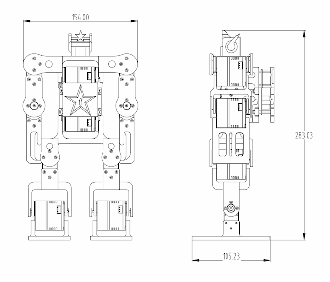
| Dimensions | 154 × 105 × 283 mm |
3. Bill of Materials
| Item | Qty |
|---|---|
| 10-DOF Robot (Assembled) | 1 |
| KM Screw M2 × 7 mm | 10 |
| KB Screw M2 × 7 mm | 10 |
| PM Screw M3 × 6 mm | 2 |
| Servo Cable 200 mm 3-pin | 2 |
10-DOF Robot Assembly Includes
- RA8-U25H-M × 10
- Structural Parts (Kit) × 1
- RUC-01 Adapter Board × 1
- Seeed XIAO ESP32-S3 × 1
- Seeed XIAO Expansion Board × 1
4. External Dimensions
5. Hardware Architecture
Drive & Power (RUC-01 Interface Board)
Serving as the power and communication hub of the entire robot, it handles bus management and power distribution:
- Servo Bus: Four onboard bus servo ports supporting daisy-chain expansion, carrying both signal and power.
- PC Configuration Interface: USB Type-C, allowing direct connection to a PC host for configuration.
- System Power: Handles voltage conversion to provide stable power to the main controller board.
- Communication Interface: Standard UART serial port for receiving commands from the upper-level main controller.
Logic Controller & Expansion (MCU + Grove Expansion Board)
The "brain" of the robot, responsible for running control algorithms and sensor data processing:
- Core MCU: Seeed Studio XIAO series development board, compact yet powerful.
- Ecosystem Expansion: The Grove expansion board breaks out a rich set of I/O interfaces.
- Primary Functions: Runs robot kinematics programs and connects sensors (ultrasonic, vision, voice, etc.) via Grove interfaces to realize interactive capabilities.
Data Flow
Debug / Edit Mode
PC --(USB)--> RUC-01 --(Bus)--> Servos
Description: Servo angles are adjusted and motion groups are saved directly via PC software without passing through the XIAO main controller.
Autonomous Run Mode
Sensor / Remote --(Signal)--> XIAO --(UART Command)--> RUC-01 --(Bus)--> Servos
Description: The XIAO autonomously controls the robot based on sensor feedback or pre-stored code.
Universal Communication Interface Reference (Must-Read for Cross-Platform Development)
Although the kit uses the XIAO ESP32S3 as the default main controller, the RUC-01 interface board is open to any external controller. Only four wires are required between the main controller and the RUC-01 for basic communication:
- 5 V / 3.3 V: The RUC-01 can back-feed stable power to the main controller.
- GND: Common ground.
- RX / TX: Standard asynchronous serial communication (UART) for sending/receiving control commands and reading servo feedback.
| No. | Interface Description | No. | Interface Description |
|---|---|---|---|
| ① | Main Power Switch | ⑤ | Adapter Board Comm UART / Grove Interface (connects to Main Controller ⑧) |
| ② | Power Input Port | ⑥ | Main Controller ESP32S3 Type-C Data Port (firmware download) |
| ③ | Servo Port × 4 | ⑦ | Seeed XIAO ESP32S3 Main Controller Board |
| ④ | Type-C Data Port (servo debug, connects to PC) | ⑧ | Main Controller Comm UART / Grove Interface (connects to RUC-01 Interface Board ⑤) |
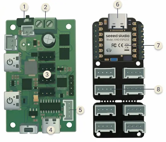
The toggle switch near the Type-C port ④ on the RUC-01 interface board, as well as the two Type-C ports shown on the left side of the diagram, are reserved for other purposes and are not used in this project. Please avoid operating them by mistake.
6. Mechanical Structure
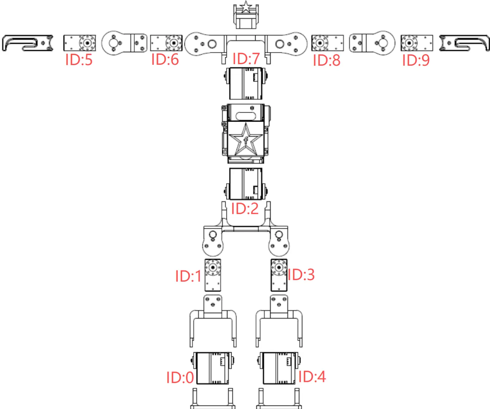
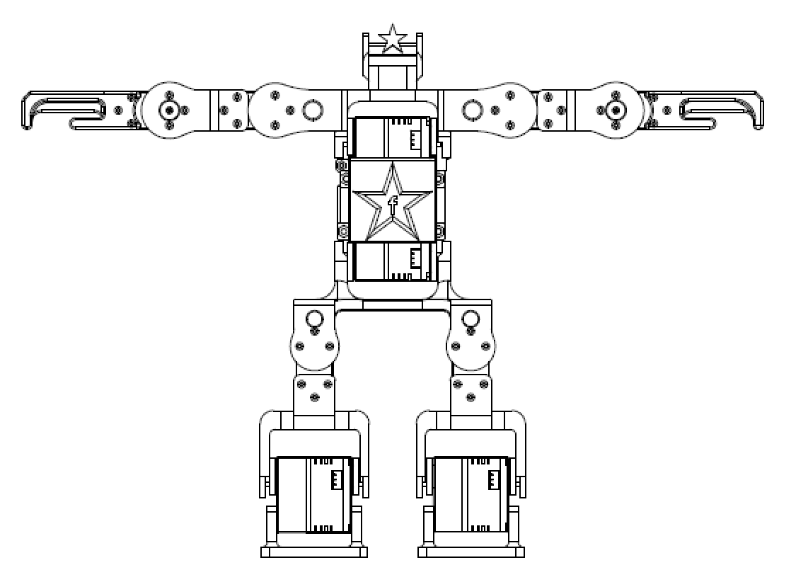
- Structural Overview & Default Servo IDs
- Zero-Degree Pose of All Servos
7. Drawings & Model Downloads
To obtain the complete 3D printing data, please visit: MakerWorld - Atom S
We will gradually provide more complete assembly videos and illustrated instructions; please stay tuned for updates to this page.
8. Running Your First Demo
Out-of-the-Box Quick Start Guide
The Atom S comes from the factory with the base control program flashed and initial assembly completed. Simply prepare a power source and a smartphone to quickly experience the robot's motions and remote control features.
Hardware Power Preparation
Due to shipping restrictions, the kit does not include a battery by default. Before starting, please prepare a compatible battery and connect it to the power port on the robot's back:
- Battery Spec: 3S 12.6 V Li-Po (lithium polymer) battery
- Battery Connector Type: T-Plug
- Power-On Check: After connecting power, the indicator LED on the main controller board (XIAO ESP32S3) will light up, indicating that the system has started.
Web Remote Controller Connection
Please enable Bluetooth on your smartphone or Bluetooth-capable PC, and choose a compatible browser based on your operating system. Because the web remote relies on the underlying Web Bluetooth API, browser compatibility is critical:
- PC (Windows / macOS): Please use Google Chrome or Microsoft Edge.
- Android: Please use Google Chrome; do not use the system default browser or open via WeChat scan.
- iOS: Safari, Chrome, and Edge do not support Web Bluetooth. Please download a third-party browser that supports the WebBLE protocol from the App Store, such as Bluefy.
Access URL: Remote Controller
- Disconnected:

- Tap the SYSTEM LINK button at the top of the interface to search for and connect to the device:
- In the Bluetooth device list that appears, select the device named ESP32_Pro_Remote and tap Pair.
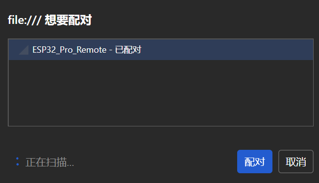
- Connected: Once connected, the robot will automatically perform a "bow" motion and return to the default standing pose, indicating that the system is ready.

Begin Your First Continuous Motion Teaching Sequence
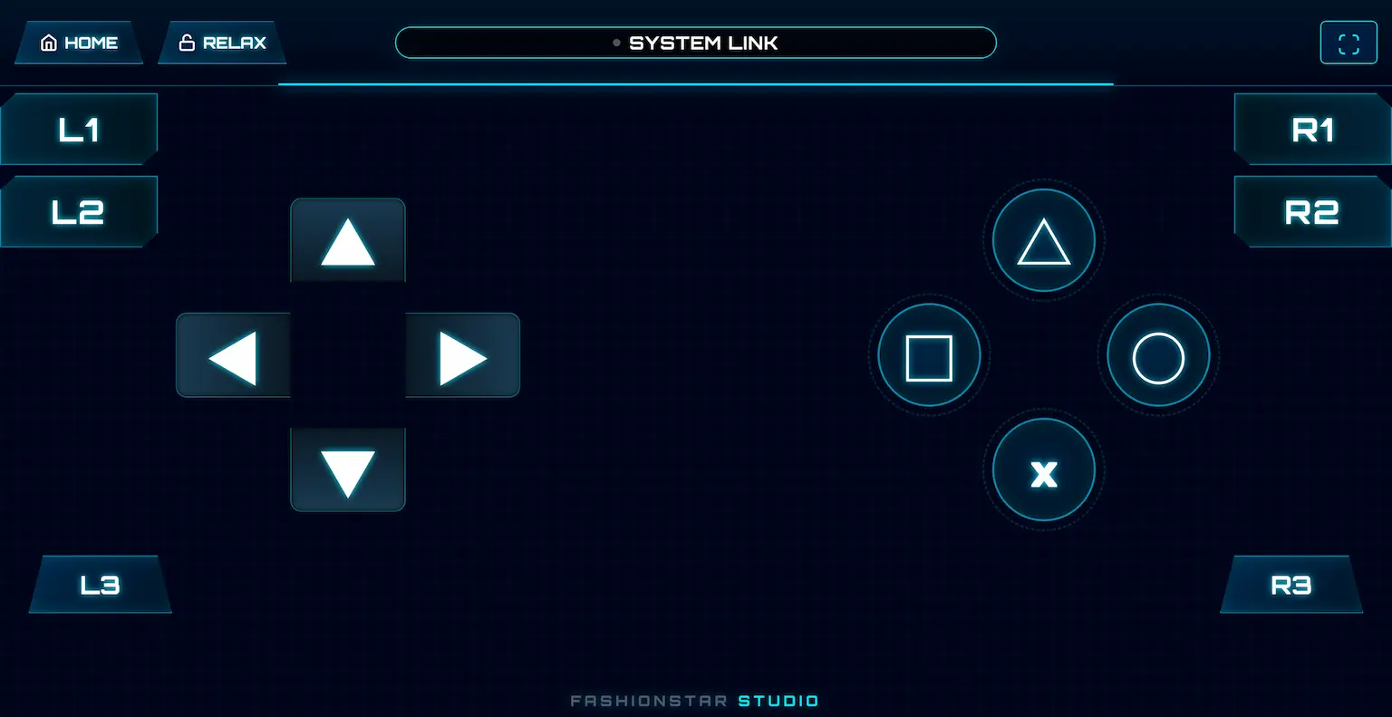
Using the web virtual gamepad, you can quickly teach the robot a continuous motion sequence without writing any code:
- Preparation: Tap the HOME button in the upper-left corner to ensure the robot is in the standard initial standing pose.
- Unlock Joints: Tap the RELAX button in the upper-left corner to put the robot into damping mode. At this point all servos are de-energized, allowing you to manually move each joint.
- Record the First Frame: Manually pose the robot, then tap the Left ◀ directional key to record the current pose.
- Record Subsequent Frames: Continue changing the robot's pose and tap Left ◀ again. Repeat this process to record a sequence of motion frames; up to 100 frames are supported by default.
- Play the Motion Sequence: After all poses are recorded, tap the Right ▶ directional key, and the robot will smoothly play back all recorded motions.
- Adjust Playback Speed: If playback is too fast or too slow, tap Up ▲ (speed up) or Down ▼ (slow down) to adjust the motion speed.
- One-Key Demo: Tap the Square □ button on the right to play the factory-default demonstration motion directly.
If you have completed the quick experience and wish to further export motion JSON, modify the main controller logic, or connect other controllers, please continue reading the following sections.
9. Open Software & Custom Motion Development
Motion Editor link:
Remote Controller link:
This section involves two browser-based applications — no installation required. Click the buttons above to open them:
- Motion Editor: Connect to the RUC-01 interface board from a PC browser to debug servos in real time, record teaching motions, and export motion groups as
.jsonfiles. - Remote Controller (Web Remote): Pair with the robot over Web Bluetooth to remotely control it and replay or adjust teaching motions.
Pose Design & Data Export (Web Motion Editor)
-
Connect & Read: Connect to the RUC-01 interface board through a PC browser to read the robot's servo states in real time.
-
Unlock & Teach: De-energize the servos into damping mode with one click, manually move the robot, and record each frame pose.
-
Arrange & Fine-Tune: Adjust the execution time and interval between keyframes, and replay in real time within the software to optimize motion fluidity.
-
Export JSON: After confirming the motion is correct, export the entire motion group as a standard
.jsonfile.
Data Integration & Firmware Flashing (ESP32 Main Controller)
- Open Source: Open the included ESP32 main controller project source code in Arduino IDE.
- Replace Code: Copy the exported
.jsondata in full and replace the existingjsonDatavariable content in theRobot.inofile. - Compile & Flash: Recompile the project and flash the updated firmware to the ESP32S3 main controller board.
Wireless Remote Control & Triggered Execution (Web Remote Terminal)
- Wireless Connection: Open the phone web remote at Remote Controller and pair with the robot.
- One-Key Trigger: Tap the Square □ button on the interface (command
0x10), and the robot will execute the newly designed motion sequence autonomously and continuously without the data cable.
Motion Editor Guide
Editor Layout
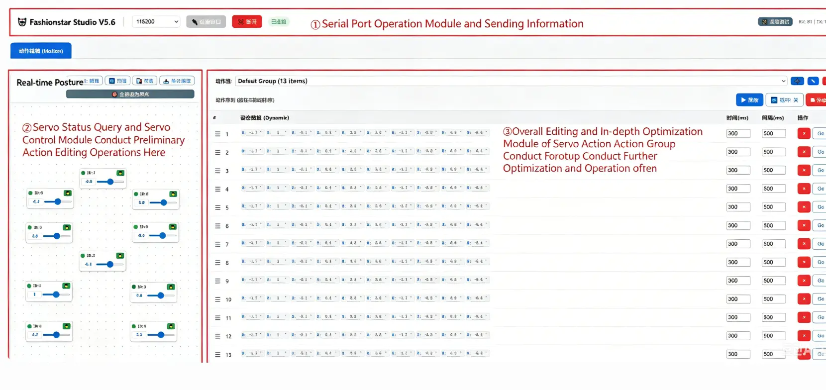
Three main modules:
- Serial port connect/disconnect and message status
- Servo status / angle query and control
- Motion group optimization and import / export
Control Reference
Connect / Disconnect Serial Port

Real-Time Pose Page
- Layout: Drag each servo control on the canvas to arrange robot parts; IDs correspond one-to-one; click to lock the layout.
- Scan: Rescan all online servos.
- Check: Over-voltage / under-voltage protection, stall, and other abnormal states.
- Read Once: Read the current angle once.
- Status Color: Green = angle control; Red = released / damping.

Angle Control via Dragging:
- Real-Time Read: Continuously read servo angles.
- Speed: Limit speed during dragging to avoid excessive motion.
- Unlock Mode: Release servos for teaching (power-off release / damping release).

Motion Group Page
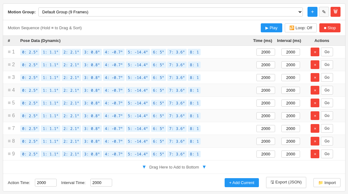
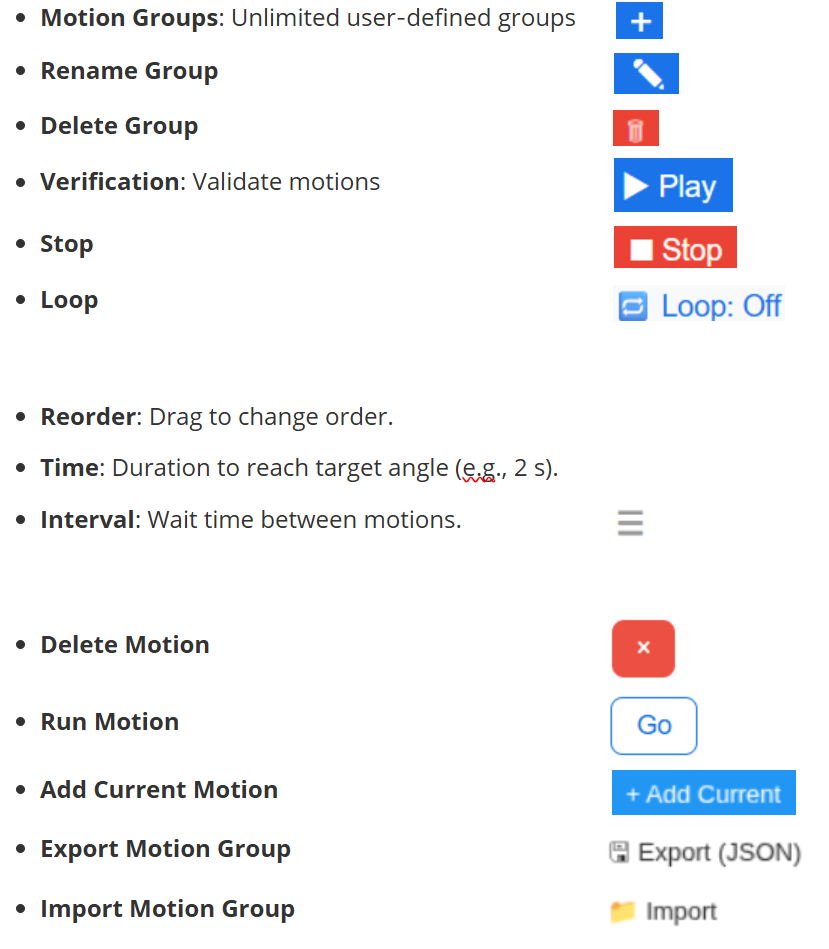
The following explains each button:
From Editor to Offline Motion (XIAO ESP32S3 Sense)
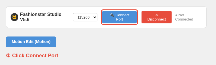
- 1. Click "Connect" to open the serial port.
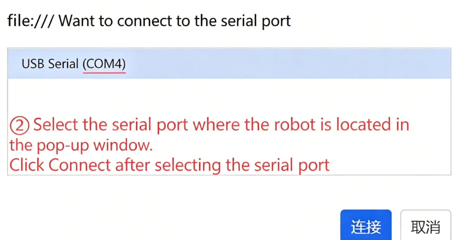
- 2. Select the target serial port.
- 3. Scan all servos on the robot.
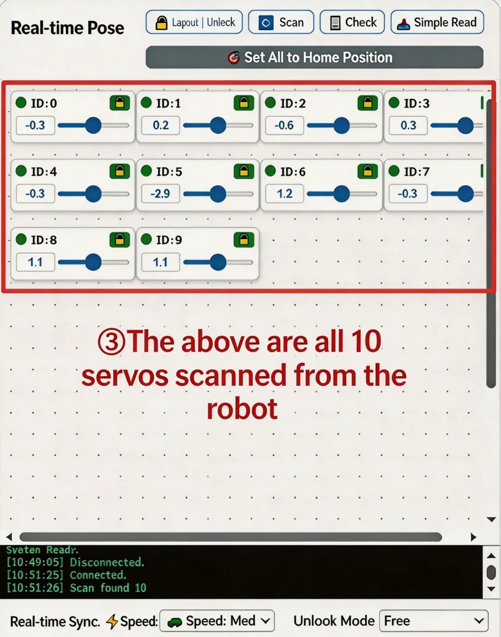
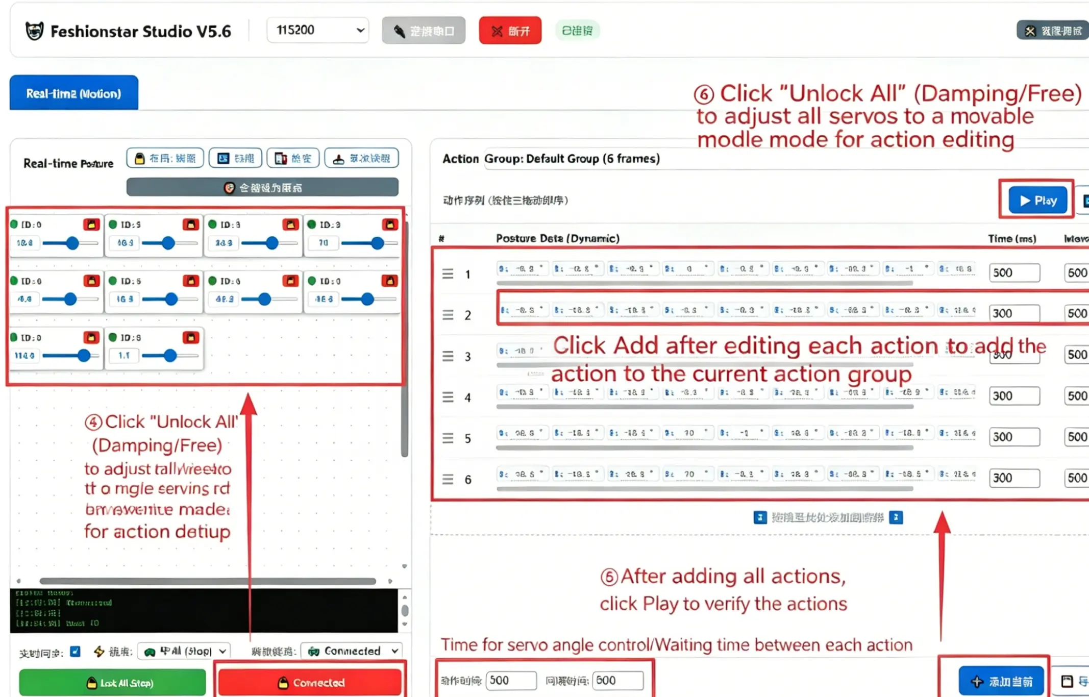
- 4. Click "Release All" to de-energize all servos for manual positioning, or unlock only the servos you need.
- 5. Set "Time" and "Interval".
- 6. After each edit, click "Add Current" to append it to the group.
- 7. Play to verify.
Note
Each motion frame can be edited individually (angle, time, interval) and verified.
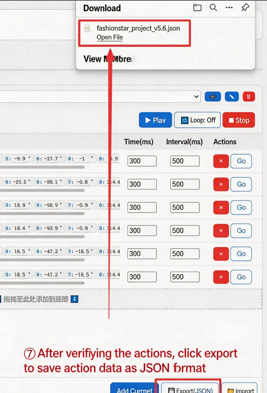
- 8. Click "Export (JSON)" to export the motion group.
- 9. Open the exported JSON and copy the
framescontent (including the outer[]).
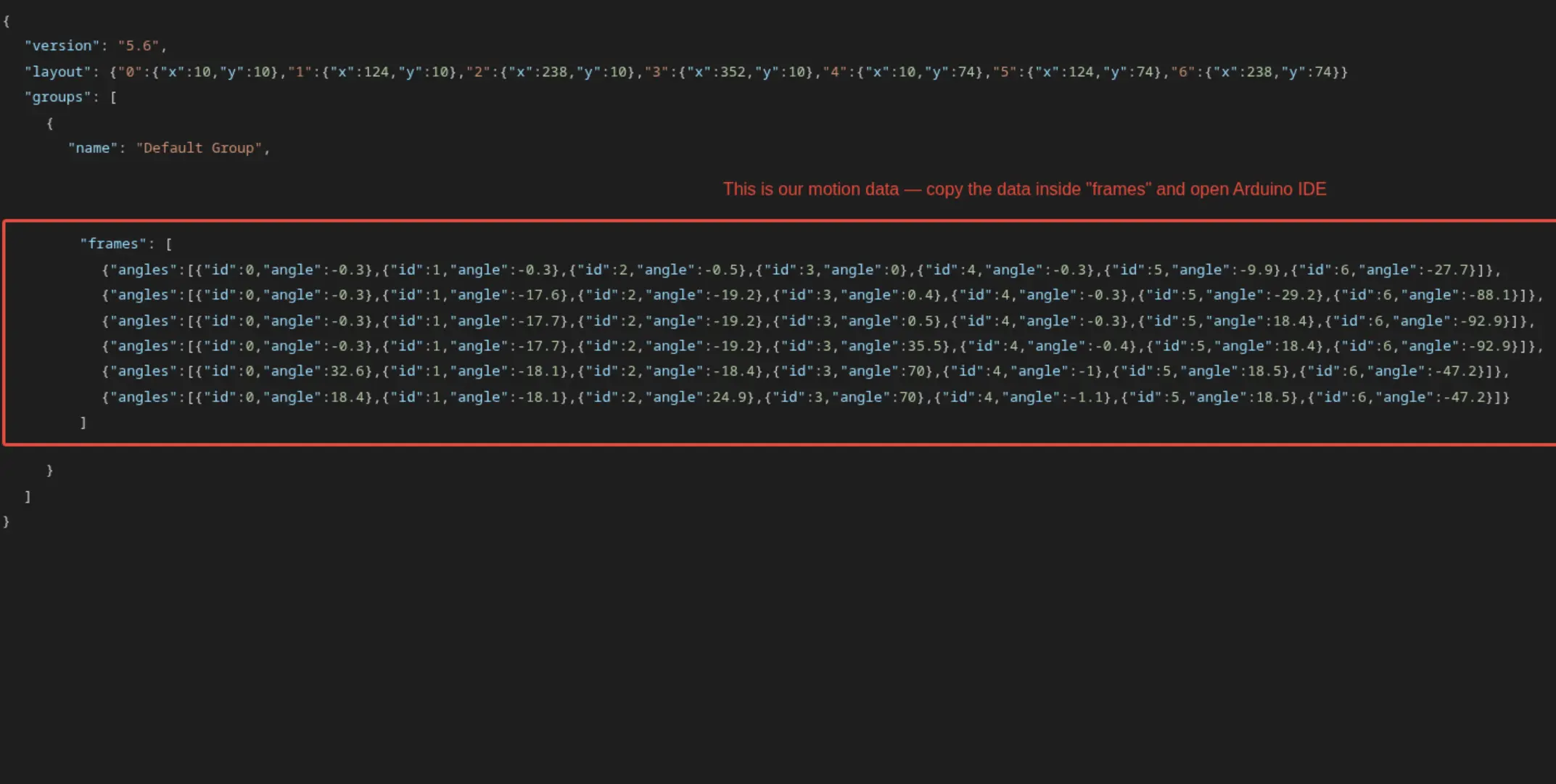
- 10. Replace the
jsonDatain the program with the copied content; after compiling and flashing, the robot can be controlled via the Bluetooth gamepad (see "Robot Control Parameters" for details).
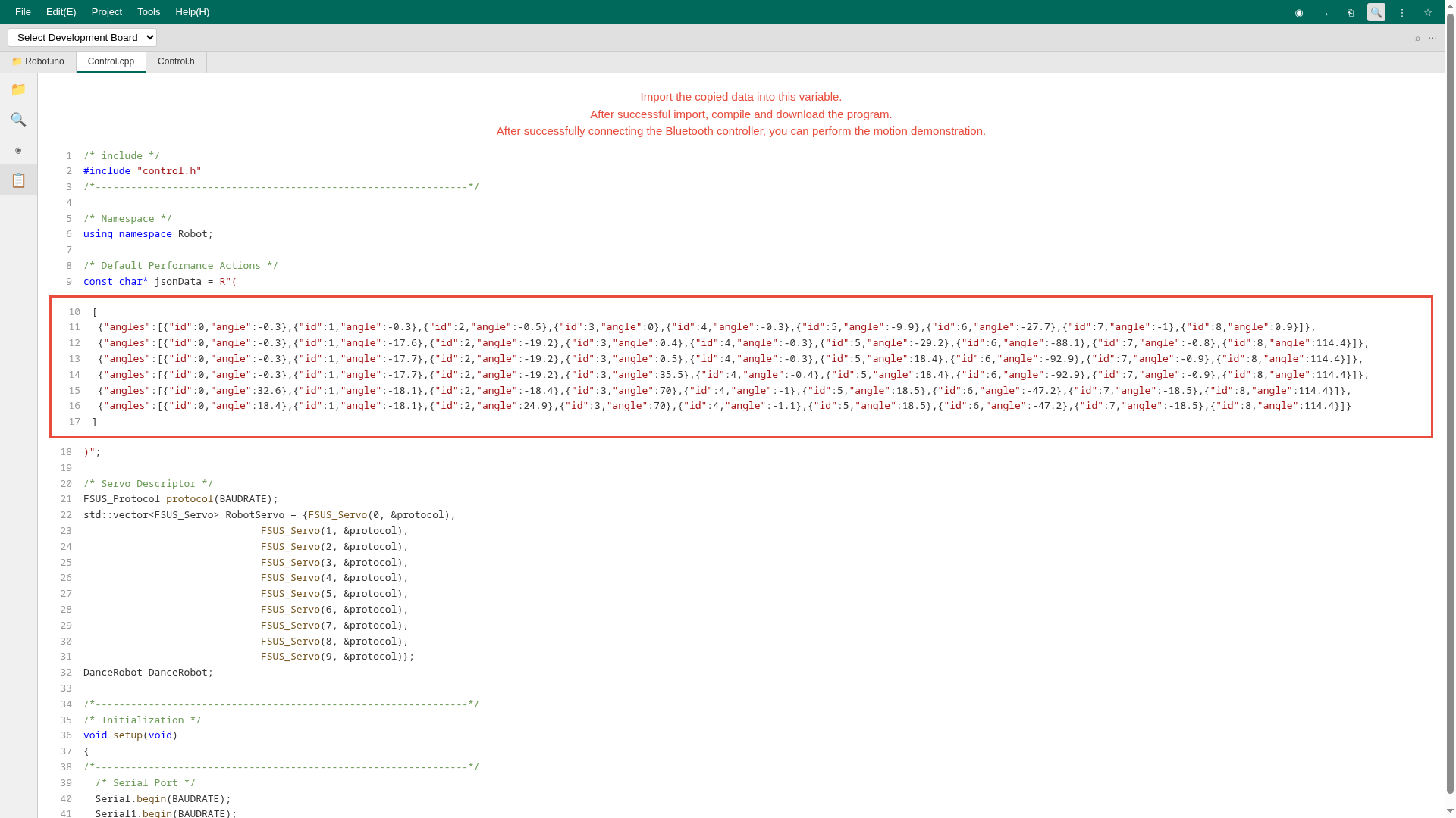
Robot Control Parameters (Adjust as Needed)
Default Values
BAUDRATE: UART baud rate.SERVO_NUM: Number of servos.
#define BAUDRATE               115200     /* Baud rate */
#define SERVO_NUM              10         /* Total number of servos */
Bluetooth (If Used)
BLE_NAME: Gamepad name.BLE_UUID: Gamepad UUID.
/* Bluetooth settings -- modify according to actual conditions */
#define BLE_NAME               "LOOKBON"  /* Bluetooth name */
#define BLE_UUID               "AE02"     /* ID for Bluetooth data reception */
Web Remote (If Used)
SERVICE_UUID: Service ID.CHARACTERSTIC_UUID: Characteristic ID.
/* ESP32 Service UUID and Characteristic UUID */
#define SERVICE_UUID           "4fafc201-1fb5-459e-8fcc-c5c9c331914b"
#define CHARACTERISTIC_UUID    "beb5483e-36e1-4688-b7f5-ea07361b26a8"
Teaching Mode
MAX_ACTIONNUM: Maximum number of motion frames allowed in teaching mode.Default_RobotRunSpeed_Demonstration: Default run speed.MIN_RobotRunSpeed_Demonstration: Slowest run speed.MAX_RobotRunSpeed_Demonstration: Fastest run speed.Adjust_RobotRunSpeed_Step: Speed adjustment step value in teaching mode (±200 per step).
#define MAX_ACTIONNUM                         100   /* Maximum number of teaching motion frames */
#define Default_RobotRunSpeed_Demonstration   1000  /* "Default" teaching run speed */
#define MIN_RobotRunSpeed_Demonstration       5000  /* "Slowest" teaching run speed */
#define MAX_RobotRunSpeed_Demonstration       500   /* "Fastest" teaching run speed */
#define Adjust_RobotRunSpeed_Step             200   /* Step value for adjusting teaching run speed */
Data Fields (Customize as Needed)
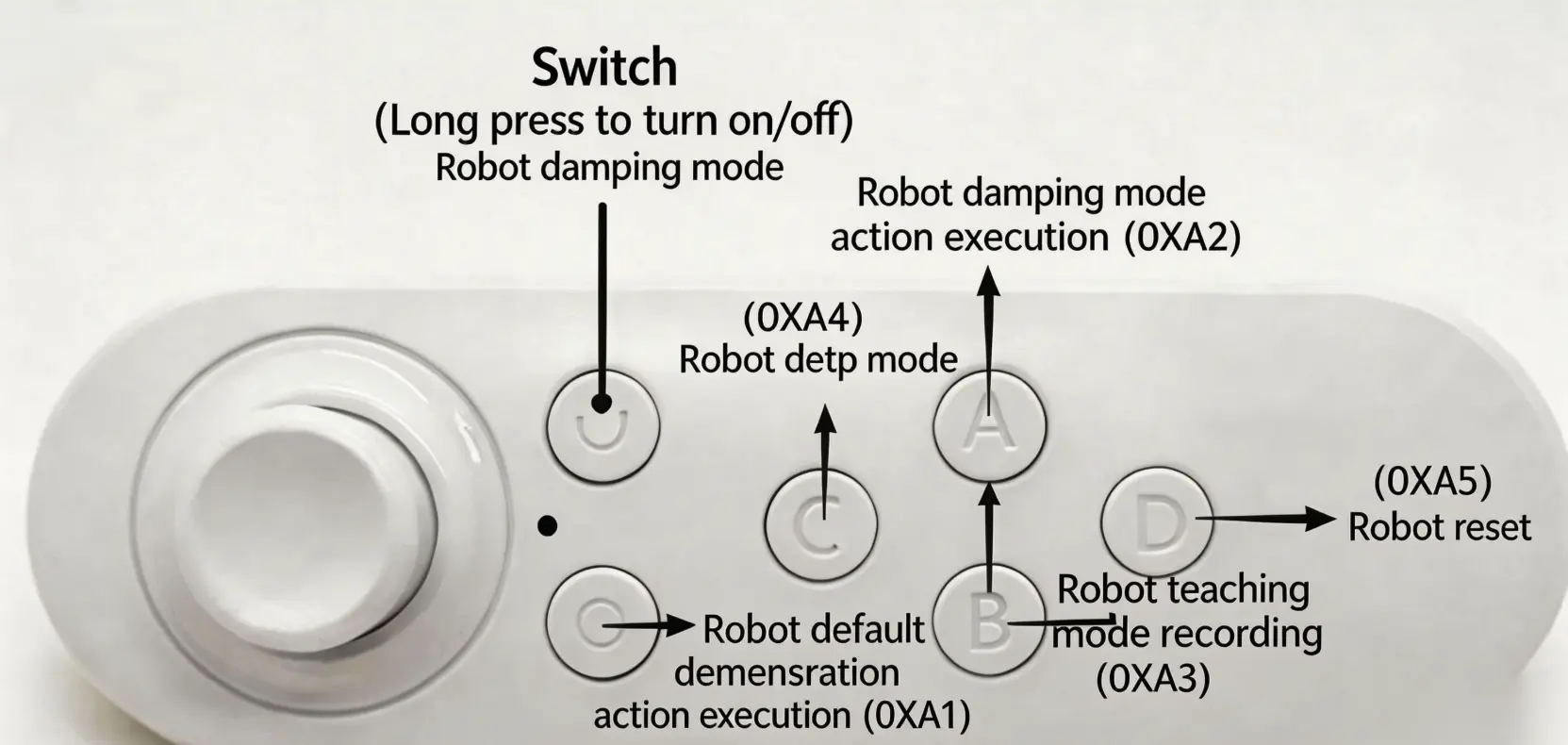
RemoteControl_DefaultDemoAction: Default demonstration motion (exported from the editor).RemoteControl_Exe: Teaching mode execution command.RemoteControl_Record: Teaching mode record command.RemoteControl_Damping: Damping mode command.RemoteControl_Reset: Reset command.RemoteControl_ReduceRunSpeed: Decrease teaching mode run speed.RemoteControl_AddRunSpeed: Increase teaching mode run speed.
Bluetooth Note: Actual controller data depends on your device; please define the buttons in code as needed.
/* Bluetooth remote control commands -- modify functions according to different commands -- adjust based on actual conditions */
#define RemoteControl_DefaultDemoAction       0xA1   /* Default demonstration motion */
#define RemoteControl_Exe                     0xA2   /* Teaching mode execution command */
#define RemoteControl_Record                  0xA3   /* Record motion command */
#define RemoteControl_Damping                 0xA4   /* Damping mode command */
#define RemoteControl_Reset                   0xA5   /* Robot reset command */
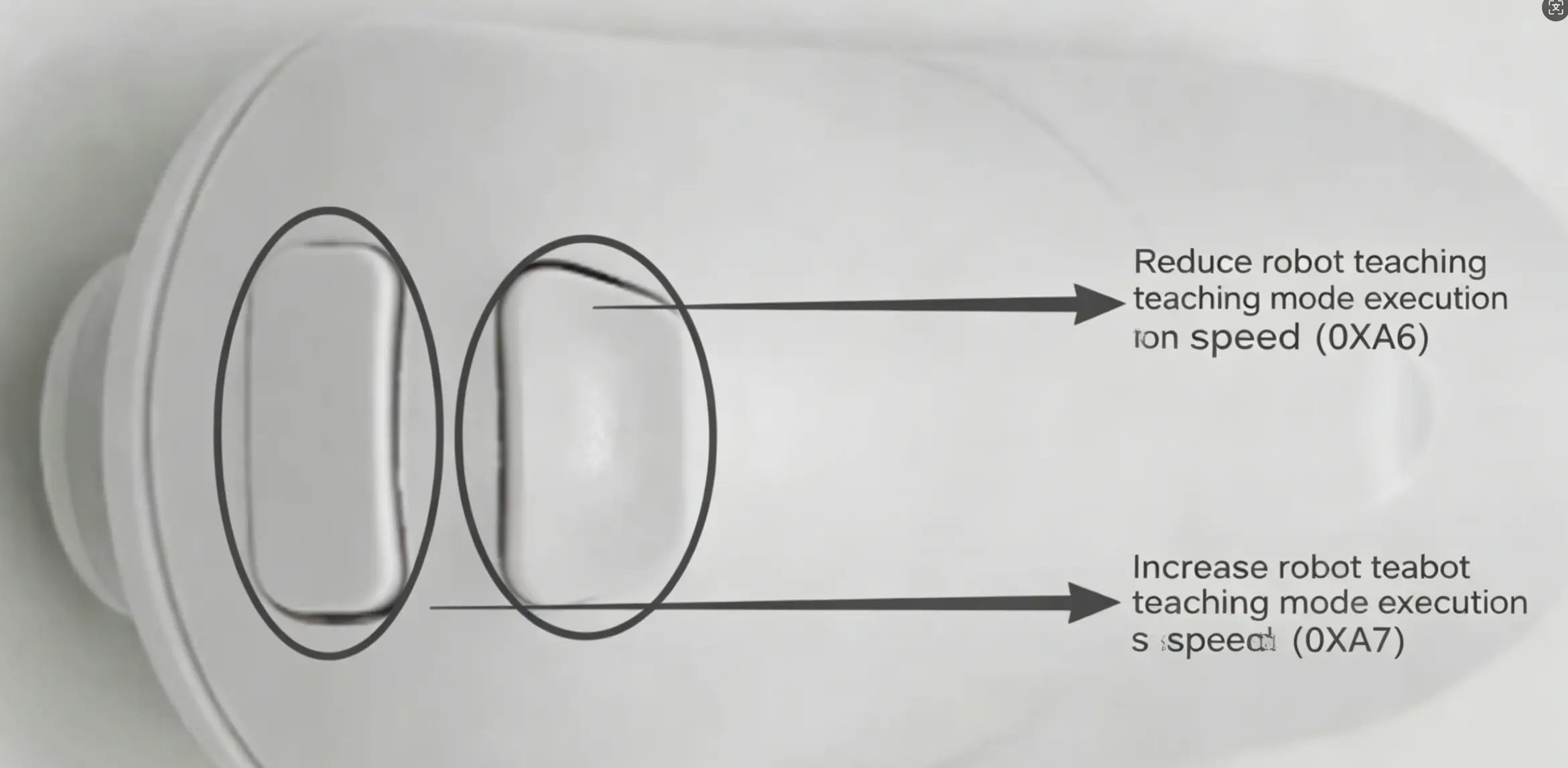
#define RemoteControl_ReduceRunSpeed          0xA6   /* Decrease teaching run speed */
#define RemoteControl_AddRunSpeed             0xA7   /* Increase teaching run speed */
Web Remote Note: Likewise, please confirm data and button mappings before integration.
/* Web remote control commands -- modify functions according to different commands -- adjust based on actual conditions */
#define RemoteControl_DefaultDemoAction       0x10   /* Default demonstration motion */
#define RemoteControl_Exe                     0x08   /* Teaching mode execution command */
#define RemoteControl_Record                  0x04   /* Record motion command */
#define RemoteControl_ReduceRunSpeed          0x02   /* Decrease teaching run speed */
#define RemoteControl_AddRunSpeed             0x01   /* Increase teaching run speed */

#define RemoteControl_Damping                 0x04   /* Damping mode command */
#define RemoteControl_Reset                   0x08   /* Robot reset command */
Reset Angles
ROBOT_RESET_POSITION_0~ROBOT_RESET_POSITION_9: Zero positions for Servo IDs 0–9 (robot reset pose).
Note: Please modify these according to your robot's reset pose.
/* Robot reset angle settings -- modify according to actual conditions */
constexpr float ROBOT_RESET_POSITION_0 = 0;
constexpr float ROBOT_RESET_POSITION_1 = 0;
constexpr float ROBOT_RESET_POSITION_2 = 0;
constexpr float ROBOT_RESET_POSITION_3 = 0;
constexpr float ROBOT_RESET_POSITION_4 = 0;
constexpr float ROBOT_RESET_POSITION_5 = 0;
constexpr float ROBOT_RESET_POSITION_6 = 0;
constexpr float ROBOT_RESET_POSITION_7 = 0;
constexpr float ROBOT_RESET_POSITION_8 = 0;
constexpr float ROBOT_RESET_POSITION_9 = 0;
Remote Control Reference
Bluetooth Gamepad
- Long-press the gamepad power button to turn it on and pair with the MCU (XIAO_ESP32S3).
- After successful pairing, the robot will bow and reset.
Motion Functions:
- "Run Motion": Execute the built-in motion.
- "Reset Robot": Return to the reset pose.
- "Damping Mode": Enter the teaching state where joints can be moved freely.
- "Record Teaching Motion": Record the current motion.
- "Execute Teaching Motion": Run the recorded motion (not cleared by default).
- "Decrease Teaching Speed": Lower the run speed (right-arm servo ID 6 swings to indicate speed).
- "Increase Teaching Speed": Raise the run speed (right-arm servo ID 6 swings to indicate speed).
10. Standard Main Controller Firmware Flashing Guide (Based on Seeed Studio XIAO ESP32S3)
This section applies only to the standard XIAO ESP32S3 main controller environment. If your project uses STM32 or Raspberry Pi, please refer directly to the multi-platform Fashionstar Servo Control SDK in the appendix.
Development Environment Setup (Arduino IDE)
Download and install the latest Arduino IDE from the official Arduino website; Arduino IDE 2.x is recommended.
Importing the ESP32 Hardware Support Package
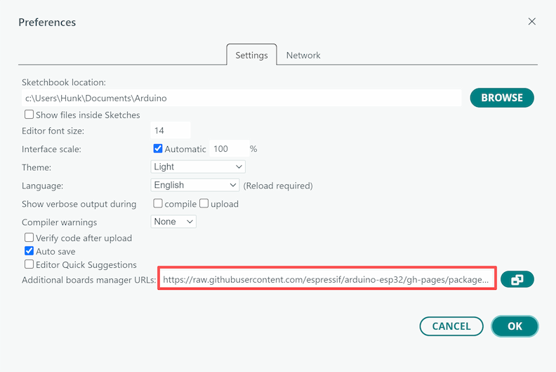
First, open the Arduino IDE Preferences:
- Windows:
File > Preferences - macOS:
Arduino IDE > Settings...orPreferences...
Enter the following URL in "Additional Boards Manager URLs":
https://raw.githubusercontent.com/espressif/arduino-esp32/gh-pages/package_esp32_index.json
Deploying the ESP32 Build Environment (Strict Version Requirement)
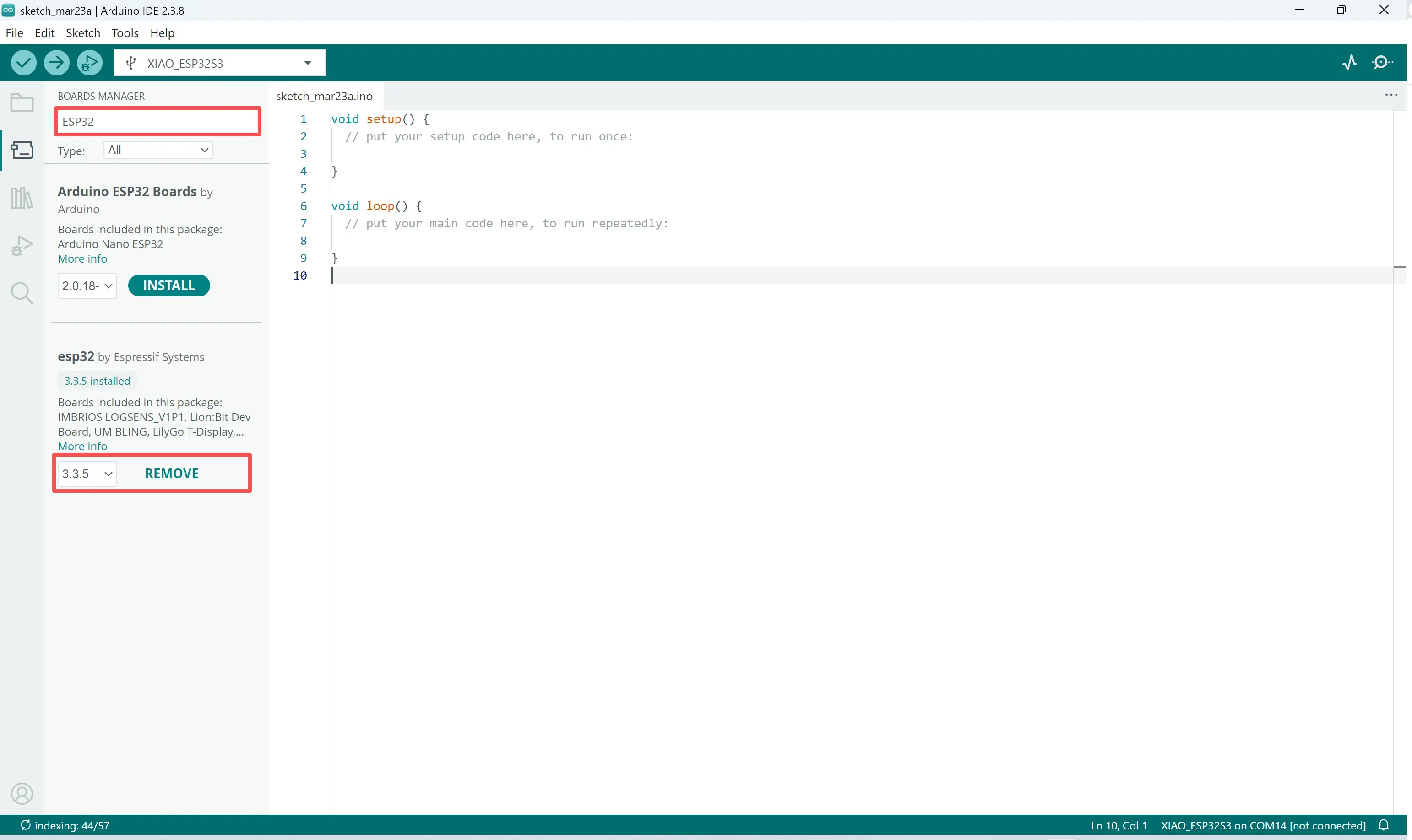
- Open
Tools > Board > Boards Manager - Search for
esp32 - Locate the package provided by
Espressif Systems - Manually select and install version 3.3.5
Do not install the latest version directly. The current project's Bluetooth and bus driver combination requires version 3.3.5; otherwise, Bluetooth or bus communication may fail to compile or run abnormally.
Installing Required Libraries (ArduinoJson and ArduinoBLE)
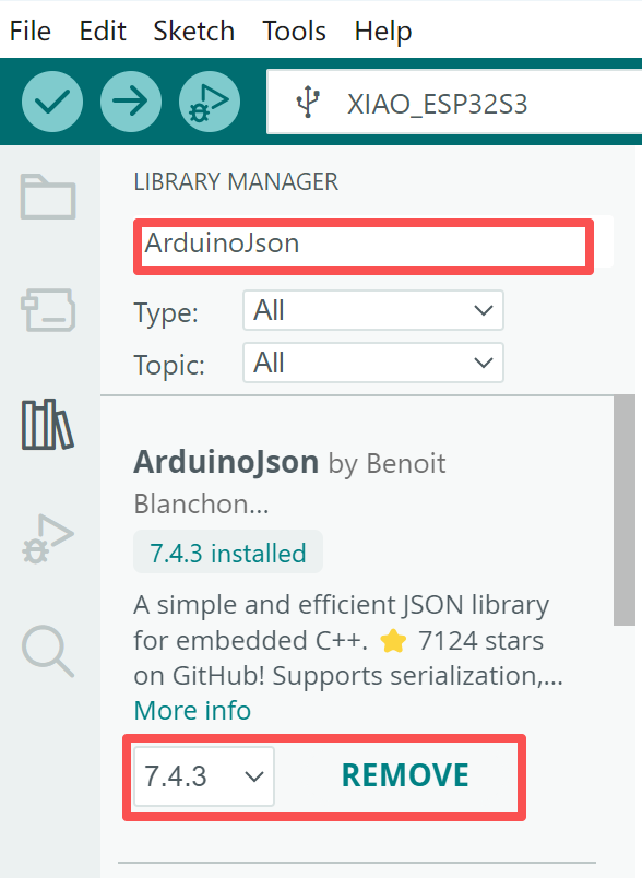
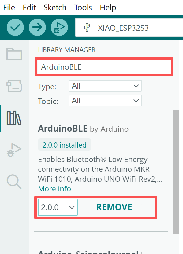
The system relies on the following third-party libraries for JSON parsing and Bluetooth services:
ArduinoJsonArduinoBLE
Installation method:
- Open
Sketch > Include Library > Manage Libraries... - Search for and install
ArduinoJson - Search for and install
ArduinoBLE
Deploying the Fashion Star Servo Core Driver SDK
To ensure correct invocation of the underlying driver, the official SDK must be installed manually:
- Locate
fashionstar-uart-servo-arduino-sdk-V2.rarin the included materials package - Extract the archive
- Copy the entire SDK folder to the Arduino default libraries directory
Default Library Path:
- Windows:
C:\Users\Username\Documents\Arduino\libraries - macOS:
~/Documents/Arduino/libraries
After copying, completely close and reopen the Arduino IDE so it reloads local libraries.
Selecting the Board and Compiling / Flashing
- Connect the XIAO ESP32S3 to your computer with a Type-C data cable
- Open
Tools > Board > esp32and selectXIAO_ESP32S3 - Open
Tools > Portand select the port corresponding to the main controller board
Port names typically appear as:
- Windows:
COM3,COM5, etc. - macOS:
/dev/cu.usbmodem...or/dev/cu.usbserial...
Finally, open the project source code (.ino) in Arduino IDE, click the Upload button in the upper-left corner, and wait for the console to show "Upload successful".
11. Low-Level Control Parameter Configuration Specification (Based on Standard Main Controller Seeed Studio XIAO ESP32S3)
After opening the project source code in Arduino IDE, the following macro definitions and constants can be modified according to actual project requirements. Please confirm the file in which each parameter resides to avoid accidental changes.
Basic Hardware Parameters
Located in Control.h
BAUDRATE: Serial baud rate for communication between the main controller and RUC-01SERVO_NUM: Total number of robot servos
/* User-modifiable robot data area */
/* define */
#define BAUDRATE 115200 /* Baud rate */
#define SERVO_NUM 10    /* Total number of servos */
UART Physical Pin Remapping
Located in Robot.ino
TX_PIN/RX_PIN: Serial pins used for communication between the ESP32S3 and the RUC-01 adapter board
/* Serial1 -- GPIO D6 = GPIO43 D7 = GPIO44 */
#define TX_PIN 43
#define RX_PIN 44
Web Remote Bluetooth Communication Parameters
Located in Robot.ino and Control.h
BLE_NAME: Bluetooth broadcast nameSERVICE_UUID/CHARACTERISTIC_UUID: Service UUID and characteristic UUID that the web remote and main controller rely on to establish communication
/* Set Bluetooth name */
BLE.setLocalName("ESP32_Pro_Remote");
/* ESP32 Service UUID and Characteristic UUID */
#define SERVICE_UUID        "4fafc201-1fb5-459e-8fcc-c5c9c331914b"
#define CHARACTERISTIC_UUID "beb5483e-36e1-4688-b7f5-ea07361b26a8"
Teaching Mode Parameter Reference
Located in Control.h
MAX_ACTIONNUM: Maximum number of motion frames recordable in teaching modeDefault_RobotRunSpeed_Demonstration: Default run speedMIN / MAX_RobotRunSpeed_Demonstration: Upper and lower limits for speed adjustmentAdjust_RobotRunSpeed_Step: Step value for each speed increase or decrease
#define MAX_ACTIONNUM 100                        /* Maximum number of teaching motion frames */
#define Default_RobotRunSpeed_Demonstration 1000 /* "Default" teaching run speed */
#define MIN_RobotRunSpeed_Demonstration 5000     /* "Slowest" teaching run speed */
#define MAX_RobotRunSpeed_Demonstration 500      /* "Fastest" teaching run speed */
#define Adjust_RobotRunSpeed_Step 200            /* Step value for adjusting teaching run speed */
Button Data and Command Macro Definitions
Located in Control.h
In wireless remote communication, the web remote packs button states into two independent variables:
btn_Main: Main operation area buttonsbtn_border: System control area buttons
Therefore, some hexadecimal commands may appear in both areas, but they correspond to different variables and will not conflict.
/* Bluetooth remote control commands -- modify functions according to different commands -- adjust based on actual conditions */
/* The following commands correspond to btn_Main (red hexadecimal labels in the mapping diagram) */
#define RemoteControl_DefaultDemoAction 0x10 /* Default demonstration motion command (Square button) */
#define RemoteControl_Exe               0x08 /* Teaching mode execution command (D-pad Right) */
#define RemoteControl_Record            0x04 /* Record motion frame command (D-pad Left) */
#define RemoteControl_ReduceRunSpeed    0x02 /* Decrease teaching run speed (D-pad Down) */
#define RemoteControl_AddRunSpeed       0x01 /* Increase teaching run speed (D-pad Up) */

/* The following commands correspond to btn_border (yellow hexadecimal labels in the mapping diagram) */
#define RemoteControl_Damping           0x04 /* Damping / release mode command (RELAX button) */
#define RemoteControl_Reset             0x08 /* Robot reset command (HOME button) */
Motion Group Data Mounting Area
Located in Robot.ino
Copy the .json data exported from the motion editor into the jsonData variable, keeping the R( and );`:
/* Default demonstration motion */
const char* jsonData = R"(
[
  // Paste the JSON data exported from the motion editor here, completely replacing this section
  {"angles":[{"id":0,"angle":0},{"id":1,"angle":0} ... ],"time":2000,"delay":500}
]
)";
JSON Buffer Allocation Size
Located in Control.cpp
If the motion sequence is too long, it may cause insufficient runtime memory or JSON parsing failure. In this case, the DynamicJsonDocument capacity can be increased appropriately:
/* Create a JSON document object with sufficient space allocated */
DynamicJsonDocument doc(4096);
Increase to 8192 or higher as needed depending on motion complexity.
Robot Reset Angle Parameters and Zero-Point Compensation
Located in Control.h
ROBOT_RESET_POSITION_0 ~ 9: Correspond to the zero initial angles of Servo IDs 0 through 9 respectively
Due to mechanical assembly tolerances, the absolute zero position of each robot may vary slightly. It is recommended to fine-tune and compensate these parameters after verifying the robot's standing pose.
/* Robot reset angle settings -- modify according to actual conditions */
constexpr float ROBOT_RESET_POSITION_0 = 0;
constexpr float ROBOT_RESET_POSITION_1 = 0;
constexpr float ROBOT_RESET_POSITION_2 = 0;
constexpr float ROBOT_RESET_POSITION_3 = 0;
constexpr float ROBOT_RESET_POSITION_4 = 0;
constexpr float ROBOT_RESET_POSITION_5 = 0;
constexpr float ROBOT_RESET_POSITION_6 = 90;
constexpr float ROBOT_RESET_POSITION_7 = 0;
constexpr float ROBOT_RESET_POSITION_8 = -90;
constexpr float ROBOT_RESET_POSITION_9 = 0;
12. Web Remote Terminal Function Dictionary and Low-Level Mapping
For browser compatibility and basic Bluetooth pairing steps, please refer to Chapter 2 of this document first. This chapter mainly explains the button layout in the control interface and the underlying hexadecimal mapping relationships to facilitate subsequent secondary development.
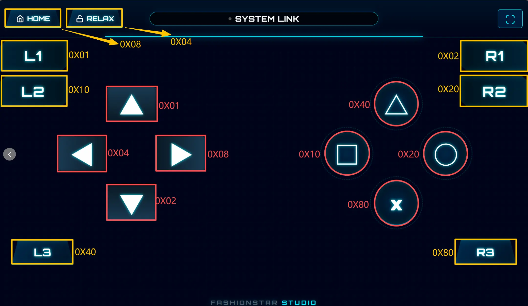
System Control Area
Corresponding code variable: btn_border
This area is located mainly at the top and edges of the interface, used to control the robot's global state:
- HOME (
0x08): Interrupt the current motion, restore the robot to the default calibrated standing pose, and clear the teaching data currently in memory - RELAX (
0x04): Enter damping / release mode, releasing the holding torque of all servos to facilitate manual teaching - Other yellow-labeled buttons: Such as
L1,L2,R1,R2,L3,R3, etc. These are not assigned any motion in the current factory demo and can be extended by developers as needed
Main Operation Area
Corresponding code variable: btn_Main
The main operation area contains the directional keys and right-side function keys, primarily responsible for motion choreography and execution:
- D-pad Left ◀ (
0x04): Record the current motion frame - D-pad Right ▶ (
0x08): Playback the currently recorded motion sequence - D-pad Up ▲ (
0x01): Increase run speed - D-pad Down ▼ (
0x02): Decrease run speed - Square □ (
0x10): Execute the defaultjsonDatamotion pre-stored in the main controller Flash - Other red-labeled buttons: Such as
△,○,×, etc. These are undefined in the current firmware and can be mapped in the low-level code as needed
FAQ
The source website page is under construction; content will be added when available.
Frequently Asked Questions
Q1: What battery should be used for the Atom-S?
A: A standard 2S or 3S Li-Po (lithium polymer) battery with an XT60 connector is recommended.
Q2: Can another main controller replace the XIAO ESP32-S3?
A: This design is optimized for the XIAO ESP32-S3, but any ESP32 development board with sufficient GPIO can be used with only minor modifications.
Q3: How do I update the firmware?
A: Connect the XIAO ESP32-S3 to your computer via USB, open Arduino IDE or PlatformIO, and upload the new program.
Q4: Where is the motion editor?
A: The web motion editor can be accessed through a browser. For detailed operation, please refer to Chapter 7.1.
Common Troubleshooting
Firmware Flash Unresponsive / Stuck State
- Symptom: Arduino IDE reports
A fatal error occurred: Failed to connect, or the upload process hangs - Fix:
- Keep the USB cable connected
- Long-press the BOOT button on the development board
- Click the Upload button in the IDE
- Release the BOOT button when the console shows
Connecting...or begins displaying transfer progress
Web Terminal Cannot Enumerate Bluetooth Devices
- Symptom: After clicking "Find Device", the Bluetooth device list is empty
- Troubleshooting:
- Verify that you are using a browser that supports the
Web Bluetooth API - Windows users: confirm the OS version is at least Win10 (1703+)
- macOS users: check System "Privacy & Security" settings to ensure the browser's Bluetooth permission is granted
- Verify that you are using a browser that supports the
Joints Weak / Unable to Hold Position
- Symptom: Firmware runs normally and communication is established, but the robot cannot effectively support a load
- Troubleshooting:
- Check whether the 3S battery charge and discharge capability are sufficient
- Check whether the bus wiring is loose or reversed
- If servos have been replaced, confirm that all 10 servo IDs (0–9) match the project definitions to avoid ID conflicts