Getting Started with Bus Servo Driver Board / XIAO Bus Servo Adapter
This wiki covers two related products: the Bus Servo Driver Board and the XIAO Bus Servo Adapter.
-
The Bus Servo Driver Board does not include an onboard XIAO ESP32-C3 microcontroller, nor does it come with a 3D-printed enclosure. It is designed to function as a general-purpose bus servo interface board, allowing you to connect and control servos via an external controller of your choice.
-
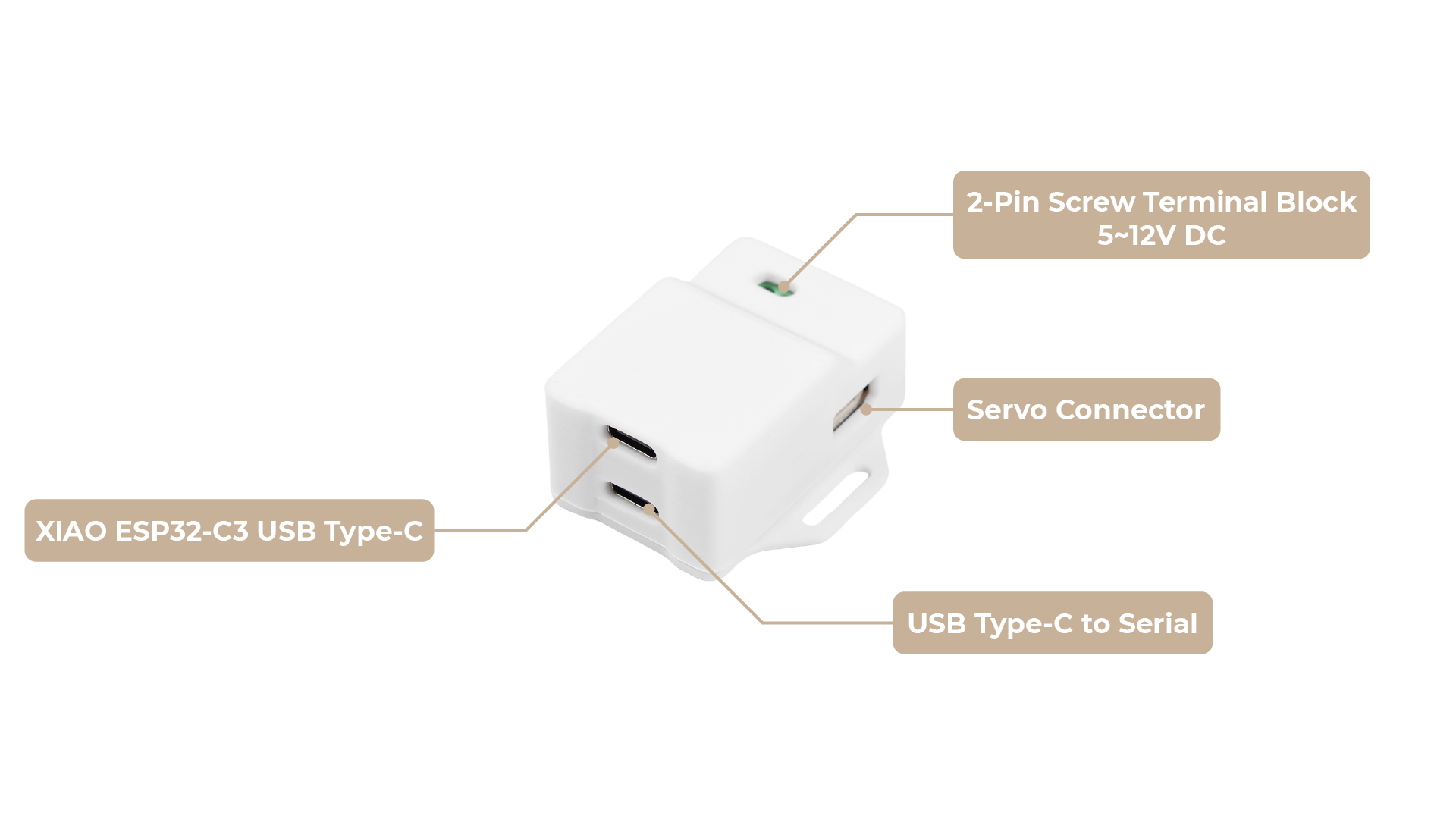
The XIAO Bus Servo Adapter, on the other hand, includes the XIAO ESP32-C3 as the main controller and comes with a 3D-printed case. With this version, you can directly control bus servos using the onboard XIAO, making it a more integrated and ready-to-use solution for robotics projects.
Please refer to the rest of this guide for details on setup and usage for both products.
| Bus Servo Driver Board | XIAO Bus Servo Adapter |
|---|---|
 |  |
Introduction
The Bus Servo Driver Board / XIAO Bus Servo Adapter is a compact and powerful hardware solution from Seeed Studio, designed to drive serial bus servos for robotics and automation projects. With support for UART communication, it enables precise control and feedback from multiple ST/SC series servos, including the Feetech SCS series (see Feetech SCS/STS/TTL Series Official Website). This makes it ideal for applications such as robotic arms, hexapods, humanoid robots, and wheeled robots requiring servo angle and load feedback.
This guide focuses on the hardware setup, physical connections, key specifications, and critical jumper settings to help users integrate the board into their projects effectively.
Always disconnect power before connecting or disconnecting servos or wiring. Ensure the input voltage matches the servo requirements to avoid damage.
Hardware Overview
- Bus Servo Driver Board
- XIAO Bus Servo Adapter
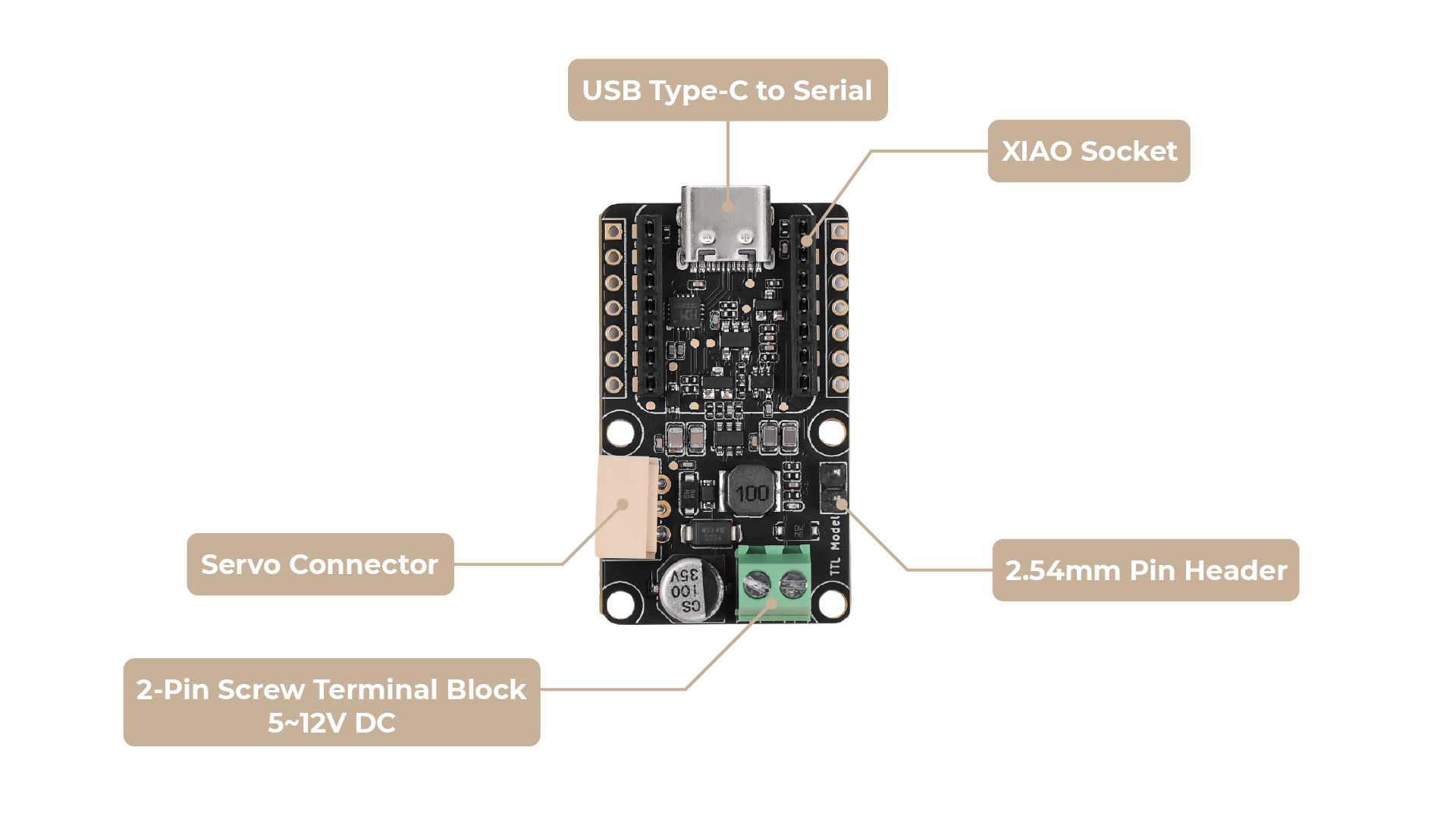
The Bus Servo Driver Board features several key connection points:
Input:
- DC IN (5.5 * 2.1mm): This is the power input for the board and the connected servos. Connect a 5~12V power supply here. Crucially, the voltage of this power supply must match the voltage requirements of your servos. For example, ST series servos typically operate at 9V, while SC series servos may require 12V.
Output:
- Servo Interface: This dedicated port is where you connect your ST/SC series bus servos. Ensure the connector is properly aligned.
Control Interface:
- UART (RX/TX): These pins provide serial communication for controlling the servos. The connection method and jumper settings depend on your host device. See below for details.
Input:
- DC IN (5.5 * 2.1mm): This is the power input for the board and the connected servos. Connect a 5~12V power supply here. Crucially, the voltage of this power supply must match the voltage requirements of your servos. For example, ST series servos typically operate at 9V, while SC series servos may require 12V.
Output:
- Servo Interface: This dedicated port is where you connect your ST/SC series bus servos. Ensure the connector is properly aligned.
Getting Started
Selecting the operating mode of the driver board (Only for Bus Servo Driver Board)
For XIAO Bus Servo Adapter, you don't need to modify any circuits to use the included XIAO ESP32-C3 to control the servos, you can skip this part directly.
The Bus Servo Driver Board offers two primary connection methods: direct UART connection and USB connection via a USB-to-UART adapter. The correct jumper setting is essential for proper operation.
UART Connection (for MCUs, XIAO, ESP32, etc.)
This method is used when connecting directly to the UART pins of a microcontroller (MCU) like an ESP32, Arduino, Seeed Studio XIAO, or a single-board computer.
-
Wiring:
- Connect the
RXpin on the Driver Board to theTXpin (D7) on your host device. - Connect the
TXpin on the Driver Board to theRXpin (D6) on your host device. - For devices like the Seeed Studio XIAO, you can directly plug the XIAO into the provided headers, ensuring correct pin alignment. This eliminates the need for separate Dupont wires for the UART connection.
- Connect the
-
Jumper Setting (Critical):
- There is no need to use a 2.54mm jumper cap to short-circuit the 2pin pin on the front of the board. (It's not shorted by default)

- There is no need to use a 2.54mm jumper cap to short-circuit the 2pin pin on the front of the board. (It's not shorted by default)
-
Powering the Host: Your host device (e.g., Raspberry Pi Zero, ESP32, XIAO) will require its own separate power supply.
USB Connection
This method is used when connecting to a computer or single-board computer with a USB port (e.g., a PC or Raspberry Pi 4B). You simply connect the control board to the computer using a USB cable.
-
Wiring:
- Simply connect the control board to your computer using a USB cable.
-
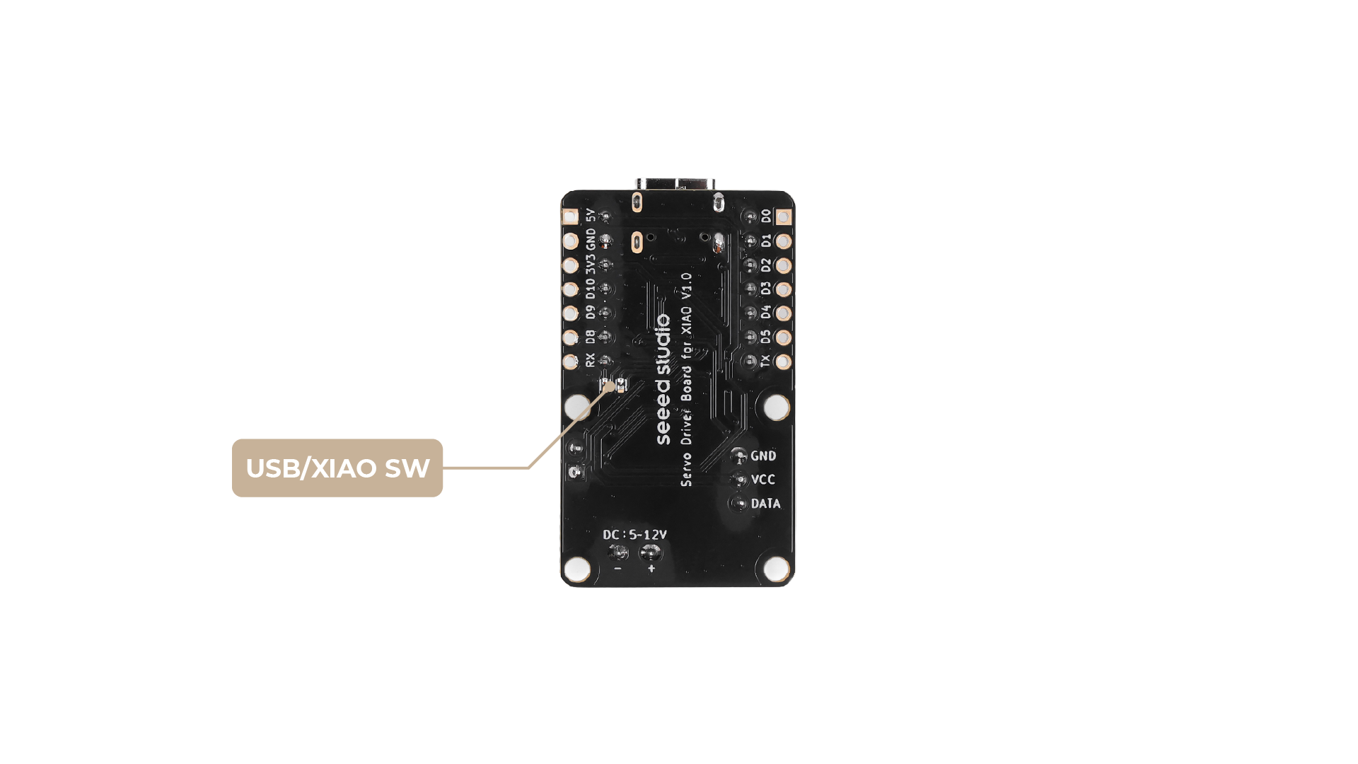
Jumper Setting (Critical):
-
Step 1. Locate the soldering jumper on the back of the board. For USB communication, you must ensure that the two pads are connected (there is a solder bridge between them).
-
Backside pads for version 1:

-
Backside pads for version 2:

-
Step 2. Use a 2.54mm jumper cap to short-circuit the 2pin pin on the front of the board. (It's not shorted by default)
-
Required Components (Before You Start)
Before connecting anything, ensure you have the following:
- Bus Servo Driver Board / XIAO Bus Servo Adapter
- Compatible ST/SC series bus servos: see Feetech SCS/STS/TTL Series Official Website.
- 5~12V Power Supply: A battery or power adapter. The voltage must match your servo's specifications.
- Host Device:
- For Direct UART: A UART-capable device like a Raspberry Pi, Arduino, ESP32, or Seeed Studio XIAO.
- For USB: A computer (PC, Mac, Linux) or a single-board computer like a Raspberry Pi 4B, plus a USB-to-UART adapter.
For XIAO Bus Servo Adapter, XIAO ESP32-C3 is built-in, so there is no need to prepare a host device.
- Connecting Wires/Adapters: Jumper wires (Dupont wires) if using direct UART (except when using XIAO with direct header connection). A USB-to-UART adapter if using the USB connection method.
If using SC series servos, confirm the power supply matches their voltage requirements. The board’s DC input label is tailored for ST series servos but supports SC series voltages as well. Incorrect jumper settings will prevent communication with the driver board.
Controlling Servos via USB
This section describes how to control multiple bus servos through the Bus Servo Driver Board using a USB connection.
Principle Overview
The Bus Servo Driver Board works by receiving serial (UART) commands from your host device (such as a PC, Raspberry Pi, or microcontroller) via USB. These commands are then relayed to the connected bus servos. By sending the appropriate serial protocol commands, you can control the position, speed, and other parameters of each servo individually.
The board itself does not interpret or generate servo control signals autonomously; instead, it acts as a transparent bridge between your host and the servos. This means you are responsible for sending the correct command packets according to your servo's communication protocol.
Example Reference
For a practical example of how to send commands to Feetech (ST/SC/STS/TTL series) bus servos, you can refer to the following Python example:
lerobot/common/robot_devices/motors/feetech.py on GitHub
This example demonstrates how to construct and send serial packets to control Feetech servos. You can adapt the code to your own host platform and programming language as needed.
Note:
- The specific command format and protocol may vary depending on your servo model.
- Please consult your servo's official documentation for the correct serial protocol and command structure.
- You will need to write or adapt a driver program that matches your servo's requirements.
For more details on the Feetech SCS/STS/TTL series protocol, see the Feetech official documentation.
Controlling Servos via XIAO
Next, we describe how to send signals to control servo motion through XIAO and how to use the library.
Arduino Library Overview
If this is your first time using Arduino, we highly recommend you to refer to Getting Started with Arduino.
Function
Before we get started developing a sketch, let's look at the available functions of the library.
-
SMS_STS(uint8_t id)—— Create a servo object with the specified ID.
Parameters:uint8_t id(servo ID)
Output: none -
void WritePos(uint8_t id, int16_t Position, uint16_t Time, uint16_t Speed)—— Set the target position, time, and speed for the servo.
Parameters:uint8_t id,int16_t Position,uint16_t Time,uint16_t Speed
Output: none -
void RegWritePos(uint8_t id, int16_t Position, uint16_t Time, uint16_t Speed)—— Set the target position, time, and speed for the servo, but execute later with Action command.
Parameters:uint8_t id,int16_t Position,uint16_t Time,uint16_t Speed
Output: none -
void RegWriteAction()—— Execute all registered RegWritePos commands.
Parameters: none
Output: none -
void WriteSpe(uint8_t id, int16_t Speed)—— Set the rotation speed for the servo.
Parameters:uint8_t id,int16_t Speed
Output: none -
void WritePosEx(uint8_t id, int16_t Position, uint16_t Time, uint16_t Speed, uint8_t ACC)—— Set position, time, speed, and acceleration.
Parameters:uint8_t id,int16_t Position,uint16_t Time,uint16_t Speed,uint8_t ACC
Output: none -
void RegWritePosEx(uint8_t id, int16_t Position, uint16_t Time, uint16_t Speed, uint8_t ACC)—— Register position, time, speed, and acceleration, execute later.
Parameters:uint8_t id,int16_t Position,uint16_t Time,uint16_t Speed,uint8_t ACC
Output: none -
void RegWriteActionEx()—— Execute all registered RegWritePosEx commands.
Parameters: none
Output: none -
int16_t ReadPos(uint8_t id)—— Read the current position of the servo.
Parameters:uint8_t id
Output:int16_t(position) -
int16_t ReadSpeed(uint8_t id)—— Read the current speed of the servo.
Parameters:uint8_t id
Output:int16_t(speed) -
int16_t ReadLoad(uint8_t id)—— Read the current load of the servo.
Parameters:uint8_t id
Output:int16_t(load) -
int16_t ReadVoltage(uint8_t id)—— Read the current voltage of the servo.
Parameters:uint8_t id
Output:int16_t(voltage) -
int16_t ReadTemper(uint8_t id)—— Read the current temperature of the servo.
Parameters:uint8_t id
Output:int16_t(temperature) -
int16_t ReadMove(uint8_t id)—— Check if the servo is moving.
Parameters:uint8_t id
Output:int16_t(1: moving, 0: stopped) -
int16_t ReadCurrent(uint8_t id)—— Read the current (electric current) of the servo.
Parameters:uint8_t id
Output:int16_t(current) -
void SetID(uint8_t id, uint8_t newid)—— Set a new ID for the servo.
Parameters:uint8_t id,uint8_t newid
Output: none -
void Load(uint8_t id)—— Enable the servo torque.
Parameters:uint8_t id
Output: none -
void Unload(uint8_t id)—— Disable the servo torque.
Parameters:uint8_t id
Output: none -
int16_t ReadTorque(uint8_t id)—— Read the torque status of the servo.
Parameters:uint8_t id
Output:int16_t(1: enabled, 0: disabled) -
void LEDAlarm(uint8_t id, uint8_t enable)—— Set the LED alarm status.
Parameters:uint8_t id,uint8_t enable
Output: none -
void Reset(uint8_t id)—— Reset the servo to factory settings.
Parameters:uint8_t id
Output: none -
void LockEprom(uint8_t id)—— Lock the EEPROM of the servo.
Parameters:uint8_t id
Output: none -
void UnlockEprom(uint8_t id)—— Unlock the EEPROM of the servo.
Parameters:uint8_t id
Output: none
XIAO Example
Now that we have our library installed and we understand the basic functions, let's run some examples for our 产品名称 to see how it behaves.
Step 1. Launch the Arduino application.
Step 2. Select your development board model and add it to the Arduino IDE.
- To use Seeed Studio XIAO ESP32-C3 for the later routines, please refer to this tutorial to finish adding.
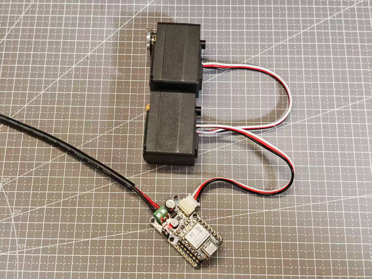
Step 3. Complete the wiring as shown. If you need to connect multiple servos, you can use the wires that come with the servos to complete the connection.
Control multiple servos
#include <SCServo.h>

// Define the correct serial port for your target board
#if defined(CONFIG_IDF_TARGET_ESP32C3) || defined(CONFIG_IDF_TARGET_ESP32C6) || defined(CONFIG_IDF_TARGET_ESP32S3)
#define COMSerial Serial0
#else
#define COMSerial Serial1
#endif

// Define RX/TX pins for the servo bus (for reference)
// Note: On ESP32, pins are usually specified in COMSerial.begin().
// For example: COMSerial.begin(1000000, SERIAL_8N1, S_RXD, S_TXD);
// If your board uses the default pins for Serial1, no extra specification is needed.
#define S_RXD D7
#define S_TXD D6

#define SERVO_NUM 2 // Number of servos

SMS_STS st; // Servo control object

// --- Servo Configuration ---
byte ID[SERVO_NUM] = {1, 2};                // IDs of the servos
u16 Speed[SERVO_NUM] = {1500, 1500};         // Set a medium speed for the servos
byte ACC[SERVO_NUM] = {50, 50};             // Set a medium acceleration for the servos
s16 Pos[SERVO_NUM] = {2048, 2048};           // Servo position array, initialized to the midpoint (2048)

void setup()
{
  // Start the main serial port for debugging and receiving commands
  Serial.begin(115200);
  // Wait a moment for the Serial Monitor to connect
  delay(2000);
  Serial.println("--- Servo Control Program Start ---");

  // Start the serial port for controlling the servos
  COMSerial.begin(1000000, SERIAL_8N1);
  st.pSerial = &COMSerial; // Associate the control object with the serial port

  Serial.println("Checking servo connection status...");
  for (int i = 0; i < SERVO_NUM; i++) {
    if (st.Ping(ID[i]) != -1) {
      Serial.print("Servo with ID ");
      Serial.print(ID[i]);
      Serial.println(" is connected.");
    } else {
      Serial.print("Error: Servo with ID ");
      Serial.print(ID[i]);
      Serial.println(" is not responding!");
    }
  }

  // --- Power-on Self-Test ---
  // This section makes the servos move automatically on power-up to confirm they are working correctly.
  Serial.println("\nExecuting power-on self-test movement...");

  // 1. Move to position 1024
  Serial.println("Moving to position 1024...");
  for(int i=0; i<SERVO_NUM; i++) {
    Pos[i] = 1024;
  }
  st.SyncWritePosEx(ID, SERVO_NUM, Pos, Speed, ACC);
  delay(2000); // Wait for the movement to complete

  // 2. Move to position 3072
  Serial.println("Moving to position 3072...");
  for(int i=0; i<SERVO_NUM; i++) {
    Pos[i] = 3072;
  }
  st.SyncWritePosEx(ID, SERVO_NUM, Pos, Speed, ACC);
  delay(2000); // Wait for the movement to complete

  // 3. Return to center position (2048) to prepare for user commands
  Serial.println("Returning to center position (2048)...");
  for(int i=0; i<SERVO_NUM; i++) {
    Pos[i] = 2048;
  }
  st.SyncWritePosEx(ID, SERVO_NUM, Pos, Speed, ACC);
  delay(1500);

  Serial.println("\n--- Initialization Complete ---");
  Serial.println("Enter 'j' to decrease the angle, or 'k' to increase it.");
  Serial.println("-----------------------------------");
}

void loop()
{
  // Check if the user has sent a command via the Serial Monitor
  if (Serial.available()) {
    String input = Serial.readString();
    input.trim(); // Remove extra spaces or newlines

    bool shouldMove = false; // Flag to indicate if a valid command was received

    if (input.startsWith("j")) {
      Serial.println("Received command: 'j'. Decreasing angle.");
      for (int i = 0; i < SERVO_NUM; i++) {
        Pos[i] -= 512; // Move a small step for easy observation
        if (Pos[i] < 0) {
          Pos[i] = 0; // Prevent going below the minimum range
        }
      }
      shouldMove = true;
    } else if (input.startsWith("k")) {
      Serial.println("Received command: 'k'. Increasing angle.");
      for (int i = 0; i < SERVO_NUM; i++) {
        Pos[i] += 512; // Move a small step
        if (Pos[i] > 4095) {
          Pos[i] = 4095; // Prevent going above the maximum range
        }
      }
      shouldMove = true;
    } else {
      Serial.print("Unknown command: '");
      Serial.print(input);
      Serial.println("'. Please enter 'j' or 'k'.");
    }

    // If a valid command was received, send the new positions to the servos
    if (shouldMove) {
      Serial.print("Moving servos to new positions: [");
      for(int i = 0; i < SERVO_NUM; i++){
        Serial.print(Pos[i]);
        if(i < SERVO_NUM - 1) Serial.print(", ");
      }
      Serial.println("]");

      st.SyncWritePosEx(ID, SERVO_NUM, Pos, Speed, ACC);
    }
  }
}
This example demonstrates how to control multiple Feetech SCS series bus servos using the XIAO and the SCServo library. The code initializes two servos, calibrates them, and allows the user to adjust their positions interactively via serial commands. When you send 'j' or 'k' through the serial monitor, the code will decrease or increase the angle of all connected servos, respectively. The current position of each servo is tracked and updated accordingly, and the new positions are sent to the servos using the SyncWritePosEx function.
How to customize for your own project:
-
Number of Servos: Change the value of
Servo_Numand update the ID, Speed, ACC, and Pos arrays to match the number and IDs of your servos. Servo IDs: Modify the ID array to match the IDs of your connected servos. -
Speed and Acceleration: Adjust the Speed and ACC arrays to set different speeds and accelerations for each servo.
-
Serial Pins: If you use different pins for UART, update S_RXD and S_TXD definitions.
-
Movement Logic: You can change the logic in the
loop()function to implement more complex or project-specific behaviors, such as responding to different serial commands, adding sensor feedback, or integrating with other hardware. -
Initial Position: Set the initial values in the
Posarray to define the starting positions of your servos.
FAQs
It's recommended to read through these FAQs before starting your project. They address common questions and potential issues.
What if the power supply voltage doesn’t match my servo?
The board and servo may malfunction or sustain damage. Always match the input voltage to your servo’s requirements.
Can I connect multiple servos at once?
Yes, multiple servos are supported, but ensure your power supply can handle the combined current draw.
Resources
Tech Support & Product Discussion
Thank you for choosing our products! We are here to provide you with different support to ensure that your experience with our products is as smooth as possible. We offer several communication channels to cater to different preferences and needs.