Grove - 2通道电感传感器(LDC1612)

Grove - 2通道电感传感器基于德州仪器(TI) LDC1612,这是一个28位电感数字转换器(LDC),用于电感传感解决方案。凭借多通道和远程传感支持,LDC1612能够以最小的成本和功耗实现电感传感的性能和可靠性优势。电感是由载流导体的磁场作用回导体本身而产生的效应。因此,通过感测电感,该传感器可以检测导体特别是附近金属的接近程度。
特性
- 2通道匹配传感器驱动
- 易于使用:需要最少配置
- 多通道支持环境和老化补偿
- 远程传感器位置>20cm,支持在恶劣环境中操作
- 线圈参数:直径:16mm/ 匝数:20
规格参数
| 项目 | 值 |
|---|---|
| 供电电压 | 3.3V / 5V |
| 结温 | -55~150℃ |
| 支持的传感器频率范围 | 1kHz~10MHz |
| 最佳检测范围 | 15mm |
| 接口 | I2C |
| I2C地址 | 0x2B(默认) 0x2A(可配置) |
| 包装尺寸 | 长: 140mm 宽: 90mm 高: 10mm |
| 毛重 | 12g |
当ADDR引脚设置为低电平时,LDC I2C地址为0x2A;当ADDR引脚设置为高电平时,LDC I2C地址为0x2B。
典型应用
- 消费电子、家电和汽车中的旋钮
- 线性和旋转编码器
- 家用电子产品、可穿戴设备、制造业和汽车中的按钮
- 制造业和家电中的键盘
- 消费产品中的滑动按钮
- 工业和汽车中的金属检测
- POS和EPOS
- 消费电子和家电中的流量计
硬件概述
引脚定义


1. 如果您不使用我们提供的线圈电感,请通过API设置Rb(电阻单位-kom)、L(电感单位-uH)、C(电容单位-pf)。用于计算和设置传感器的相应频率寄存器。
2. 传感器板上有一个INT焊盘,当转换完成时它变为低电平,否则保持高电平,但您应该配置传感器的相应寄存器。
工作原理
LDC1612基于测量LC振荡器的参数工作,该振荡器由PCB铜走线和电容器组成。
LDC1612能够测量当与LC振荡器磁耦合的导电物体接近时,维持LC振荡所需提供的能量。由于振荡器电路的功率损耗与导电物体的阻抗成正比,而阻抗值受物体距离的影响,因此可以用来确定物体与LC振荡器之间的距离。在这种情况下,PCB铜走线可以看作是一个阻抗传感器。
支持的平台
| Arduino | Raspberry Pi | |||
|---|---|---|---|---|
 |  |  |  |  |
上述提到的支持平台表示该模块的软件或理论兼容性。在大多数情况下,我们只为Arduino平台提供软件库或代码示例。我们无法为所有可能的MCU平台提供软件库/演示代码。因此,用户必须编写自己的软件库。
入门指南
与Arduino一起使用
硬件
所需材料
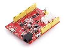
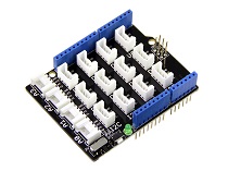
| Seeeduino V4.2 | Base Shield | Grove - 2通道电感传感器 |
|---|---|---|
 |  |  |
| 立即购买 | 立即购买 | 立即购买 |
-
步骤1. 将Grove - 2通道电感传感器(LDC1612)连接到Grove-Base Shield的I^2^C端口。
-
步骤2. 将Grove - Base Shield插入Seeeduino。
-
步骤3. 通过USB线将Seeeduino连接到PC。

现在,我们将演示如何运行硬币距离检测的代码,如果您希望运行其他程序,步骤类似。
软件
如果这是您第一次使用Arduino,我们强烈建议您在开始之前先查看Arduino入门指南。
-
步骤1. 从Github下载Grove-2-Channel_Inductive_Sensor-LDC1612库。
-
步骤2. 参考如何安装库为Arduino安装库。
-
步骤3. 重启Arduino IDE。打开示例,您可以通过以下三种方式打开:
-
在Arduino IDE中通过路径直接打开:文件 --> 示例 -->Seeed Inductive Sensor LDC1612--> coin_test_demo。

-
在您的计算机中点击basic_demo.ino打开,您可以在文件夹XXXX\Arduino\libraries\examples\coin_test_demo\coin_test_demo.ino中找到它,XXXX是您安装Arduino IDE的位置。

-
或者,您可以点击代码块右上角的图标
 将以下代码复制到Arduino IDE的新草图中。
-
硬币演示 该程序允许用户检测硬币到铜走线的距离。
#include "Seeed_LDC1612.h"

LDC1612 sensor;
const u32 DISTANCE_00=44000000;  //do not detect
const u32 DISTANCE_00_01=60000000;  // distance:<1mm
const u32 DISTANCE_01_05=45000000;  // distance:1mm~5mm
const u32 DISTANCE_05_10=44250000; // distance:5mm~10mm
const u32 DISTANCE_10_15=44080000; // distance:10mm~15mm
const u32 DISTANCE_15_20=44020000; // distance:15mm~20mm

void setup()
{
    Serial.begin(115200);
    delay(100);
    Serial.println("start!");

    sensor.init();

    if(sensor.single_channel_config(CHANNEL_0))
    {
        Serial.println("can't detect sensor!");
        while(1);
    }


}


void loop()
{
    u32 result_channel1=0;
    u32 result_channel2=0;

    /*shows the status of sensor.*/
    //sensor.get_sensor_status();

    /*Get channel 0 result and parse it.*/
    sensor.get_channel_result(CHANNEL_0,&result_channel1);

    /*Test the distance between the coin and the sensor.
    Note that the accuracy is for reference only.
    Please suspend the sensor during the test! */
    if(0!=result_channel1)
    {
        if(result_channel1<DISTANCE_00)
        {
            Serial.println("There is no coin here!");
        }

        if(result_channel1>=DISTANCE_00_01)
        {
            Serial.println("The distance between the COIN is 0~1mm");
        }

        if(result_channel1<DISTANCE_00_01&&result_channel1>=DISTANCE_01_05)
        {
            Serial.println("The distance between the COIN is 1~5mm");
        }

        if(result_channel1<DISTANCE_01_05&&result_channel1>=DISTANCE_05_10)
        {
            Serial.println("The distance between the COIN is 5~10mm");
        }

        if(result_channel1<DISTANCE_05_10&&result_channel1>=DISTANCE_10_15)
        {
            Serial.println("The distance between the COIN is 10~15mm");
        }

        if(result_channel1<DISTANCE_10_15&&result_channel1>=DISTANCE_15_20)
        {
            Serial.println("The distance between the COIN is 15~20mm");
        }

        if(result_channel1<DISTANCE_15_20&&result_channel1>=DISTANCE_00)
        {
            Serial.println("The distance between the COIN is more than 2mm");
        }

    }

    delay(1000);
}
库文件可能会更新。此代码可能不适用于更新后的库文件,因此我们建议您使用前两种方法。
如果一切顺利,您将看到以下结果
The distance between the COIN is 5~10mm
The distance between the COIN is 5~10mm
There is no coin here!
The distance between the COIN is 10~15mm
The distance between the COIN is 5~10mm
The distance between the COIN is 1~5mm
The distance between the COIN is 5~10mm
The distance between the COIN is 5~10mm
基础演示
basic_demo.ino 的代码
#include "Seeed_LDC1612.h"

LDC1612 sensor;


void setup()
{
    Serial.begin(115200);
    delay(100);
    Serial.println("start!");

    sensor.init();

    if(sensor.single_channel_config(CHANNEL_0))
    {
        Serial.println("can't detect sensor!");
        while(1);
    }


}


void loop()
{
    u32 result_channel1=0;
    u32 result_channel2=0;

    /*shows the status of sensor.*/
    //sensor.get_sensor_status();

    /*Get channel 0 result and parse it.*/
    sensor.get_channel_result(CHANNEL_0,&result_channel1);

    /*sensor result value.you can make a lot of application according to its changes.*/
    if(0!=result_channel1)
    {
        Serial.print("result_channel0 is ");
        Serial.println(result_channel1);
    }

    delay(1000);
}
如果一切顺利,您将看到以下结果
start!
17:06:16.418 -> fsensor =3.74
17:06:16.418 -> result_channel0 is 44387993
result_channel0 is 44387847
result_channel0 is 43476136
result_channel0 is 43799295
result_channel0 is 48988429
result_channel0 is 48828492
result_channel0 is 48682647
result_channel0 is 48845443
多通道演示
此示例展示了多通道测量,请注意 LDC1612 支持两个通道。
您可以按如下所示连接线圈 1:

muti_channel_demo.ino 的代码
#include "Seeed_LDC1612.h"
#include "math.h"

LDC1612 sensor;

void setup()
{
    Serial.begin(115200);
    delay(100);
    Serial.println("start!");

    sensor.init();

    /*Enable INT-PIN,Interrupted after measurement is completed.*/
    //sensor.set_ERROR_CONFIG(0x01);

    /*multiple channel use case configuration.*/
    if(sensor.LDC1612_mutiple_channel_config())
    {
        Serial.println("can't detect sensor!");
        while(1);
    }
}


void loop()
{
    u32 result_channel0=0;
    u32 result_channel1=0;

    /*shows the status of sensor.*/
    //sensor.get_sensor_status();

    /*sensor result value.you can make a lot of application according to its changes.*/
    sensor.get_channel_result(0,&result_channel0);
    sensor.get_channel_result(1,&result_channel1);

    if(0!=result_channel0)
    {
        Serial.print("result_channel0 is ");
        Serial.println(result_channel0);
    }
    if(0!=result_channel1)
    {
        Serial.print("result_channel1 is ");
        Serial.println(result_channel1);
    }
    delay(1000);
}
如果一切顺利,您将看到以下结果
start!
17:04:34.063 -> fsensor =3.74
17:04:34.063 -> fsensor =3.74
17:04:34.063 -> result_channel0 is 44399351
17:04:34.063 -> result_channel1 is 43599310
result_channel0 is 44648052
17:04:35.078 -> result_channel1 is 43803483
result_channel0 is 44786926
17:04:36.056 -> result_channel1 is 43990824
result_channel0 is 44266733
17:04:37.069 -> result_channel1 is 43305067
result_channel0 is 44767222
17:04:38.092 -> result_channel1 is 43553768
result_channel0 is 46081099
17:04:39.068 -> result_channel1 is 45089497
result_channel0 is 44681202
17:04:40.083 -> result_channel1 is 43207588
can't detect coil Coil Inductance!!!
17:04:41.098 -> can't detect coil Coil Inductance!!!
can't detect coil Coil Inductance!!!
17:04:42.106 -> result_channel0 is 89478485
can't detect coil Coil Inductance!!!
17:04:43.081 -> result_channel0 is 49469095
result_channel0 is 51374493
17:04:44.113 -> result_channel1 is 49895644
can't detect coil Coil Inductance!!!
17:04:45.090 -> can't detect coil Coil Inductance!!!
can't detect coil Coil Inductance!!!
在 basic_demo 和 muti_channel_demo 示例中,您需要记住每个输出都对应电感强度。输出与电感强度之间存在函数关系,如果您对更多信息感兴趣,可以参考德州仪器(TI)提供的 数据手册 LDC1612。
原理图在线查看器
资源
-
[PDF] LDC1612数据手册
技术支持与产品讨论
感谢您选择我们的产品!我们在这里为您提供不同的支持,以确保您使用我们产品的体验尽可能顺畅。我们提供多种沟通渠道,以满足不同的偏好和需求。
