Grove - 模拟麦克风

Grove - 模拟麦克风基于高性能 SiSonic MEMS 技术,为开源硬件行业提供了一款极低噪声、低功耗、可靠且小巧的麦克风,并且在恶劣条件下具有改进的性能。
Grove - 模拟麦克风是需要出色音频性能的声音传感器的理想选择。它可以提供高达20dB的增益,还具有低功耗、最大射频保护的特点,这使其成为Arduino和Raspberry Pi的完美麦克风。我们的特色产品 ReSpeaker Core v2.0 也采用了MEMS技术和与Grove - 模拟麦克风相同的麦克风。如果您想要一个出色的麦克风,这就是您的选择。
特性
- 高性能SiSonic MEMS技术
- 极低噪声、低功耗且可靠
- 紧凑优雅的设计
此声音传感器用于检测周围是否有声音,请不要使用该模块来收集声音信号。例如,您可以使用它制作声控灯,但不能用作录音设备。
应用
- 声音传感器
- 声音信号采集
- 语音识别
- 录音
规格参数
| 项目 | 值 |
|---|---|
| 尺寸 | 20mm x 20mm |
| 工作电压 | 3.3V |
| 工作电流 | 5mA |
| 工作温度范围 | -40 °C 到 100 °C |
有关Grove模块的更多详细信息,请参考 Grove系统
支持的平台
| Arduino | Raspberry Pi | |||
|---|---|---|---|---|
 |  |  |  |  |
上述提到的支持平台是/是该模块软件或理论兼容性的指示。在大多数情况下,我们只为Arduino平台提供软件库或代码示例。不可能为所有可能的MCU平台提供软件库/演示代码。因此,用户必须编写自己的软件库。
开始使用
如果这是您第一次使用 Arduino,我们强烈建议您在开始之前先查看 Arduino 入门指南。
与 Arduino 一起使用
硬件
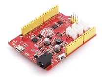
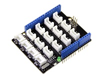
| Seeeduino V4.2 | Base Shield | Grove-模拟麦克风 |
|---|---|---|
 |  |  |
| 立即购买 | 立即购买 | 立即购买 |
- 步骤 1. 将 Grove-声音传感器连接到 Grove-Base Shield 的 A0 端口。
- 步骤 2. 将 Grove - Base Shield 插入 Seeeduino,并通过 USB 线将 Seeeduino 连接到 PC。

如果我们没有 Grove Base Shield,我们也可以直接将 Grove-声音传感器连接到 Seeeduino,如下所示。
| Seeeduino | Grove-声音传感器 |
|---|---|
| 5V | Red |
| GND | Black |
| A1 | White |
| A0 | Yellow |
软件
- 步骤 1. 请将下面的代码复制到 Arduino IDE 并上传到 arduino。如果您不知道如何上传代码,请查看 如何上传代码。
/*
  Analog input, analog output, serial output

  Reads an analog input pin, maps the result to a range from 0 to 255 and uses
  the result to set the pulse width modulation (PWM) of an output pin.
  Also prints the results to the Serial Monitor.
*/

// These constants won't change. They're used to give names to the pins used:
const int analogInPin = A0;  // Analog input pin that the potentiometer is attached to
const int analogOutPin = 9; // Analog output pin that the LED is attached to

int sensorValue = 0;        // value read from the pot
int outputValue = 0;        // value output to the PWM (analog out)

void setup() {
  Serial.begin(9600);      // initialize serial communications at 9600 bps
}

void loop() {
  sensorValue = analogRead(analogInPin);        // read the analog in value
  outputValue = map(sensorValue, 0, 1023, 0, 255);       // map it to the range of the analog out
  analogWrite(analogOutPin, outputValue);               // change the analog out value

  Serial.println(outputValue);    // print the results to the Serial Monitor

  // wait 2 milliseconds before the next loop for the analog-to-digital
  // converter to settle after the last reading:
  delay(2);
}
- 步骤 2. 点击 Serial > Plotter 获取传感器的变化曲线。请制造一些噪音来查看数值的变化。

与 Wio Terminal 一起使用
硬件
| Wio Terminal | Grove-模拟麦克风 |
|---|---|
 |  |
| 立即购买 | 立即购买 |
硬件连接

步骤 1 通过 Grove 线将 Grove-模拟麦克风插入 Wio Terminal,同时通过 USB 线将 Wio Terminal 连接到 PC。
步骤 2 将演示代码复制到您的 Arduino IDE 并上传。
软件
#include "seeed_line_chart.h" //include the library

TFT_eSPI tft;
#define LINE_DIS 0X00
#define STRING_DIS 0X01
#define max_size 30 //maximum size of data
doubles data;       //Initilising a doubles type to store data
int brightness;
TFT_eSprite spr = TFT_eSprite(&tft); // Sprite

const int MIC = A0; //the microphone amplifier output is connected to pin A0
int adc;
int dB, PdB; //the variable that will hold the value read from the microphone each time
uint8_t mode = LINE_DIS;
void setup()
{
    Serial.begin(9600); //sets the baud rate at 9600 so we can check the values the microphone is obtaining on the Serial Monitor
    pinMode(A0, INPUT);
    pinMode(WIO_KEY_C, INPUT_PULLUP);
    pinMode(WIO_BUZZER, OUTPUT);
    tft.begin();
    spr.createSprite(TFT_HEIGHT, TFT_WIDTH);
    spr.setRotation(3);
    tft.setRotation(3);
}

void loop() {

    if (digitalRead(WIO_KEY_C) == LOW) {
        mode ++;
        if(mode > STRING_DIS ) mode = LINE_DIS;
        while(!digitalRead(WIO_KEY_C));
    }
    display(mode);
}

void display(uint8_t mode)
{
    adc = analogRead(MIC); //Read the ADC value from amplifer
    //Serial.println (adc);//Print ADC for initial calculation
    dB = (adc + 83.2073) / 7.003; //Convert ADC value to dB using Regression values

    if(dB > 50)
    {
        analogWrite(WIO_BUZZER, 128);

    }else{
        analogWrite(WIO_BUZZER, 0);
    }

    spr.fillSprite(TFT_WHITE);

    if (data.size() == max_size)
    {
        data.pop(); //this is used to remove the first read variable
    }
    data.push(dB); //read variables and store in data

    //Settings for the line graph title
    auto header = text(0, 0)
                      .value("MIC DB Readings")
                      .align(center)
                      .valign(vcenter)
                      .width(tft.width())
                      .thickness(2);

    header.height(header.font_height() * 2);
    header.draw(); //Header height is the twice the height of the font
    if (LINE_DIS == mode){
    //Settings for the line graph
    auto content = line_chart(20, header.height()); //(x,y) where the line graph begins
    content
        .height(tft.height() - header.height() * 1.5) //actual height of the line chart
        .width(tft.width() - content.x() * 2)         //actual width of the line chart
        .based_on(0.0)                                //Starting point of y-axis, must be a float
        .show_circle(false)                           //drawing a cirle at each point, default is on.
        .value(data)                                  //passing through the data to line graph
        .color(TFT_RED)                               //Setting the color for the line
        .draw();
    } else if (STRING_DIS == mode){
        for(int8_t line_index = 0;line_index < 5 ; line_index++)
        {
            spr.drawLine(0, 50 + line_index, tft.width(), 50 + line_index, TFT_GREEN);
        }
        auto header =  text(0, 0)
                    .thickness(1);
        spr.setFreeFont(&FreeSansBoldOblique24pt7b);
        if(dB > 50){
            spr.setTextColor(TFT_RED);
        }else{
            spr.setTextColor(TFT_BLUE);
        }
        spr.drawFloat(dB,2,70,110);
        spr.drawString(" dB",80 + 100,110,1);
    }
    spr.pushSprite(0, 0);
    delay(100);
}
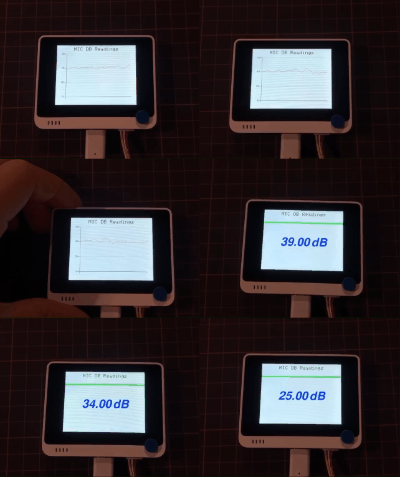
如果一切正常,图像将显示在 Wio Terminal 的屏幕上。

原理图在线查看器
资源
技术支持与产品讨论
感谢您选择我们的产品!我们在这里为您提供不同的支持,以确保您使用我们产品的体验尽可能顺畅。我们提供多种沟通渠道,以满足不同的偏好和需求。