Grove Arduino 项目初学者套件
项目 1:入侵报警器
概述
本教程介绍如何制作入侵报警器。
特点
- PIR 运动传感器可以检测区域内的人员,然后触发报警。
所需组件
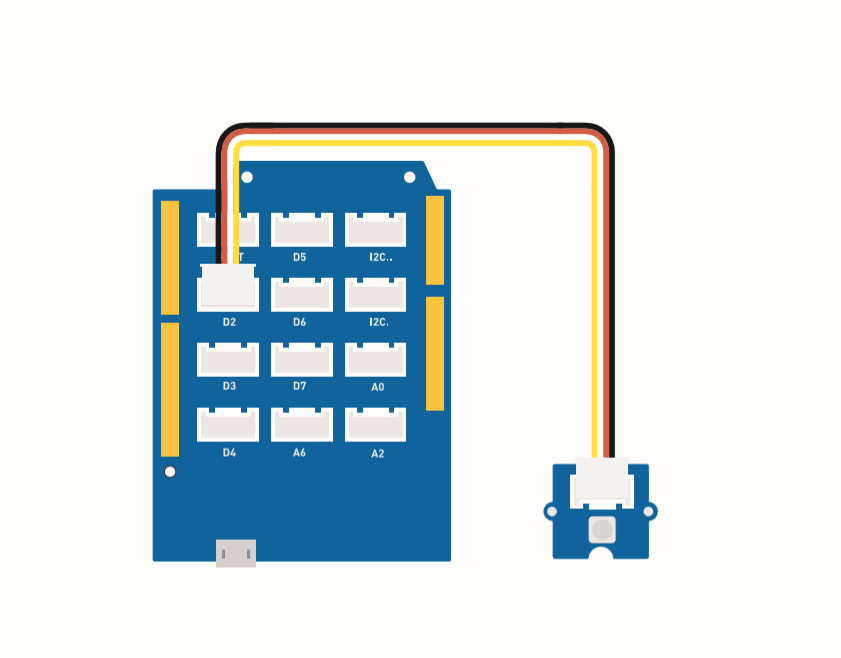
硬件连接
请按照相同颜色的线将每个传感器连接到板上,将 PIR 运动传感器的 grove 线缆连接到 D2。
组装说明
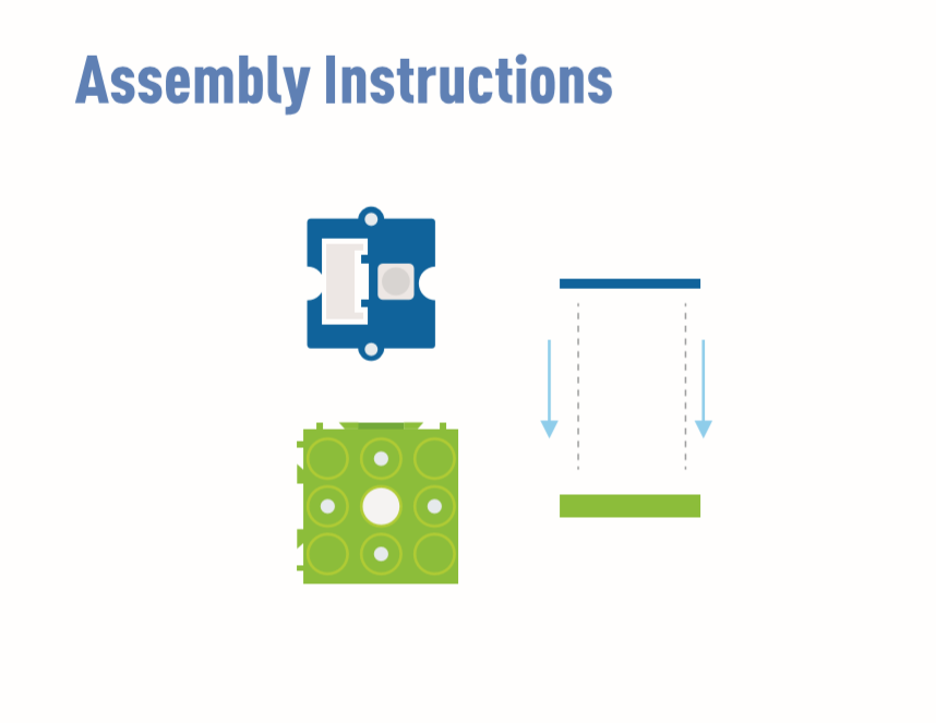
蜂鸣器 (D5) 和 LED (D4) 已嵌入在板上。
Arduino 说明
步骤 1. 下载 Arduino IDE
步骤 2. 按照连接图将所有传感器连接到板上。
步骤 3. 将迷你 PIR 运动传感器放置在检测位置。
步骤 4. 复制代码粘贴到 Arduino IDE 中然后上传。
代码
#define PIR_MOTION_SENSOR 2//Use pin 2 to receive the signal from the module

int BuzzerPin = 5;     // set D5 as buzzer
int LED_RAD = 4;       // set D4 as LED

void setup() {
  Serial.begin(9600);
  pinMode(PIR_MOTION_SENSOR, INPUT);
  pinMode(BuzzerPin, OUTPUT);
  pinMode(LED_RAD, OUTPUT);
}

void loop() {

  if (digitalRead(PIR_MOTION_SENSOR)) {
    analogWrite(BuzzerPin, 100);
    digitalWrite(LED_RAD, HIGH);
    delay(3000);
    analogWrite(BuzzerPin, 0);
    digitalWrite(LED_RAD, LOW);
    delay(4000);
  }

}
项目 2:摆动风扇
概述
本教程介绍如何制作一个迷你风扇,放置在您的房间里保持凉爽。
特性
- 自动摆动风扇
所需组件
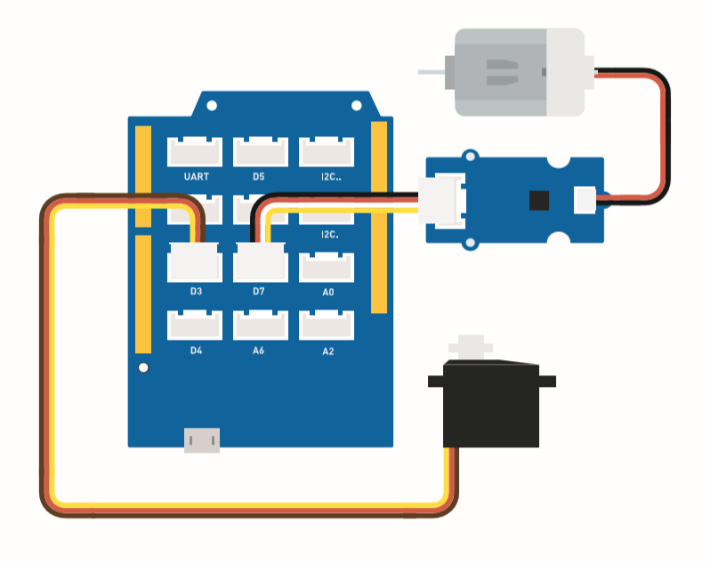
硬件连接
请将风扇 Grove 线缆连接到 D7,舵机 Grove 线缆连接到 D3。
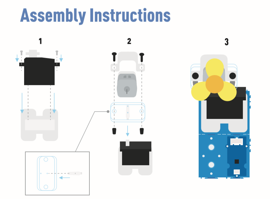
组装说明
Arduino 说明
步骤 1. 下载 Arduino IDE
步骤 2. 复制代码并粘贴到 Arduino IDE 中
步骤 3. 选择当前端口:工具 -> 端口 -> COM(数字)
步骤 4. 上传代码
请将风扇放置在安全位置。
代码
#include <Servo.h>

Servo myservo;  // create servo object to control a servo

int pos = 0;    // variable to store the servo position
int fanPin = 7;  // set D6 as control switch
int fanState = LOW;

void setup() {
    Serial.begin(9600);
    myservo.attach(3);  // attaches the servo on pin 2 to the servo object
    pinMode(fanPin, OUTPUT);
}

void loop() {

 fanState = HIGH;
 digitalWrite(fanPin, fanState);

   for (pos = 0; pos <= 100; pos += 1) { // goes from 0 degrees to 100 degrees
    // in steps of 1 degree
    myservo.write(pos);              // tell servo to go to position in variable 'pos'
    delay(40);                       // waits 15ms for the servo to reach the position
  }
  for (pos = 100; pos >= 0; pos -= 1) { // goes from 100 degrees to 0 degrees
    myservo.write(pos);              // tell servo to go to position in variable 'pos'
    delay(40);                       // waits 15ms for the servo to reach the position
  }
}
项目 3:遥控摆动风扇
概述
本教程介绍如何制作一个遥控摆动风扇。
特性
-
风扇电源由控制器控制。
-
风扇摆动方式可以使用遥控器控制。
所需组件
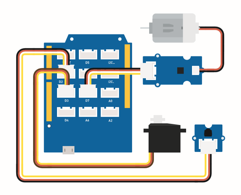
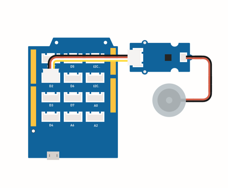
硬件连接
请按照相同颜色的线将每个传感器连接到板上。请将风扇 grove 线缆连接到 D7,舵机 grove 线缆连接到 D3,IR grove 线缆连接到 D2。
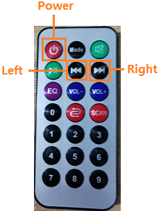
这是控制器按钮功能。
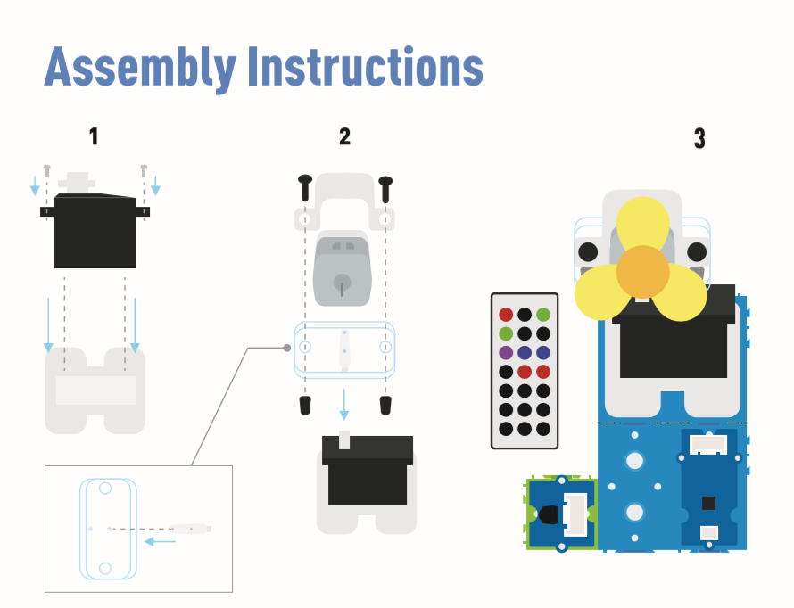
组装说明
Arduino 说明
步骤 1. 按照连接图将所有传感器连接到板上。
步骤 2. 下载 Aruidno IDE
步骤 3. 导航到 Sketch -> Include Library -> Manage Libraries,搜索 IRremote 然后安装它。
步骤 4. 复制代码粘贴到 Aruino IDE 中然后上传。
步骤 5. 将风扇放置在安全位置,尝试按下按钮确保它能安全工作。
参考如何 安装库 为 Arduino 安装库。
代码
#include <IRremote.h>
#include <Servo.h>

Servo myservo;  // 创建舵机对象来控制舵机
int RECV_PIN = 2; // 设置引脚2作为红外控制

IRrecv irrecv(RECV_PIN);

decode_results results;

int pos = 90;    // 存储舵机位置的变量
int fanPin = 7;  // 设置D6作为控制开关
int fanState = LOW;
int IO = 0;

void setup()
{
  Serial.begin(9600);
  Serial.println("Enabling IRin");  // 提醒启用红外
  irrecv.enableIRIn(); // 启动接收器
  Serial.println("Enabled IRin");
  myservo.attach(3);  // 将引脚2上的舵机连接到舵机对象
  pinMode(fanPin, OUTPUT);

}

//  power_encode 2155829415     left  2155870215  right  2155821255

void loop() {
  if (irrecv.decode(&results)) { //检查红外信号
    if (results.value == 2155829415) {    // 电源关闭/开启
      IO++;
      if (IO % 2 == 0) {
        fanState = HIGH;
        digitalWrite(fanPin, fanState);
        delay(100);
      }
      else {
        fanState = LOW;
        digitalWrite(fanPin, fanState);
        delay(100);
      }
    }

    if (results.value == 2155821255 ) {    // 风扇向左摆动
      for (pos; pos <= 89; pos += 1) { // 从0度到90度
        // 以1度为步长
        myservo.write(pos);              // 告诉舵机转到变量'pos'中的位置

        delay(40);                       // 等待15ms让舵机到达位置
        if (irrecv.decode(&results)) {
          irrecv.resume();
          if (results.value == 2155870215)
            break;
        }
      }
    }

    if (results.value == 2155870215 ) {    // 风扇向右摆动
      for (pos; pos >= 1; pos -= 1) { // 从90度到0度
        myservo.write(pos);              // 告诉舵机转到变量'pos'中的位置
        delay(40);                       // 等待15ms让舵机到达位置

        if (irrecv.decode(&results)) {
          irrecv.resume();
          if (results.value == 2155821255)
            break;
        }
      }
    }
    Serial.println(pos);
    Serial.println(results.value, HEX);
    Serial.println(results.value);
    irrecv.resume();                    //接收下一个指令

  }
  delay(100);
}
项目 4:智能加湿器
概述
本教程介绍如何制作水雾化装置来保持室内湿度正常。
特点
-
当湿度较低时自动使用水雾化功能。
-
实时显示温度和湿度。
所需组件
硬件连接
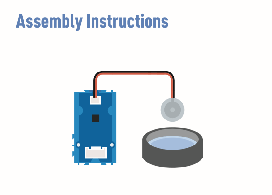
请按照相同颜色的线将每个传感器连接到板上。 将 Grove 水雾化模块的线缆连接到 D2。
组装说明
Arduino 说明
步骤 1. 按照连接图将所有传感器连接到板上。
步骤 2 下载 Arduino IDE
步骤 3 导航到 Sketch -> Include Library -> Manage Libraries,搜索 U8g2 然后安装它。
步骤 4 下载 Grove_Temperature_And_Humidity_Sensor 库 并安装它
步骤 5. 复制代码粘贴到 Arduino IDE 中然后上传。
步骤 6. 准备一个装满水的容器,然后将水雾化模块放在水上。
参考如何 安装库 来为 Arduino 安装库。
准备一些纸巾放在水上,让水雾化模块保持漂浮。纸巾的作用是将水引导到换能器并保持换能器的上侧在水面之上。
代码
#include <Arduino.h>
#include <U8x8lib.h>

#include "DHT.h"
#define DHTTYPE DHT11   // DHT 11
#define DHTPIN 3     // what pin we're connected to
DHT dht(DHTPIN, DHTTYPE);

#include <Wire.h>

U8X8_SSD1306_128X64_NONAME_HW_I2C u8x8(/* reset=*/ U8X8_PIN_NONE);

void setup(void) {
  Serial.begin(115200);
  u8x8.begin();
  u8x8.setFlipMode(1);
  Wire.begin();
  dht.begin();
  pinMode(2,INPUT);
}

void loop(void) {
  float temp_hum_val[2] = {0};
  int b;
  int c;
  if (!dht.readTempAndHumidity(temp_hum_val)) {
     b = temp_hum_val[0];
     c = temp_hum_val[1];
  }
  else{
    Serial.println("Failed to get temprature and humidity value.");
    }
  u8x8.setFont(u8x8_font_chroma48medium8_r);   // choose a suitable font
  u8x8.setCursor(0, 0);
  u8x8.print("Temp: ");
  u8x8.setCursor(5, 0);
  u8x8.print(c);
  u8x8.setCursor(8, 0);
  u8x8.print("*C");
  u8x8.setCursor(0, 10);
  u8x8.print("Hum: ");
  u8x8.setCursor(5, 10);
  u8x8.print(b);
  u8x8.setCursor(8, 10);
  u8x8.print("%");
  u8x8.setCursor(0, 20);
  u8x8.print("atomizer: ");

  if(b > 70){
  u8x8.setCursor(9, 20);
  u8x8.print("OFF");
  digitalWrite(2, LOW);    // atomization stopped
  }
  if(b <= 70) {
  u8x8.setCursor(9, 20);
  u8x8.print("ON ");
  digitalWrite(2, HIGH);   // atomize
    }
  delay(1000);

}
项目 5:超声波雷达
概述
本教程介绍如何制作超声波雷达来检测物体和距离。
特性
-
检测物体距离
-
扫描周围是否存在物体
所需组件
硬件连接
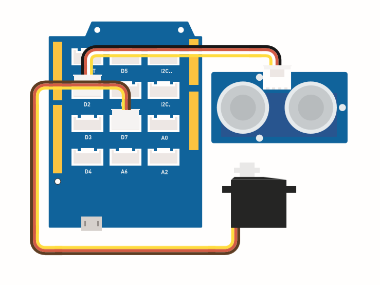
请按照图片,将超声波传感器 Grove 线缆连接到 D2,将舵机连接到 D7。
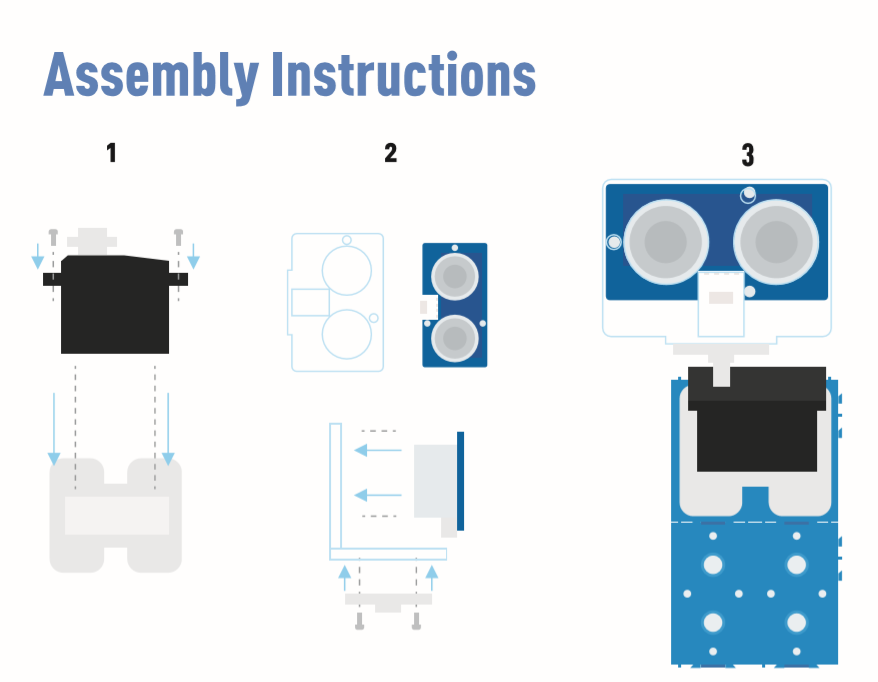
组装说明
Arduino 说明
步骤 1. 按照连接图将线缆插入端口。
步骤 2. 下载 Arduino IDE
步骤 3. 下载 Processing
步骤 4. 从 Github 下载 UltrasonicRanger 库。
步骤 5. 复制雷达代码并粘贴到 Arduino IDE 中,然后上传。
步骤 6. 下载 Processing 用于显示雷达扫描地图。
步骤 7. 复制雷达-Processing 代码并粘贴到 Processing 中。
步骤 8. 舵机开始摆动后,点击 Processing 软件中的播放按钮。
如果您不知道如何安装库,请点击这里。
雷达代码
#include <Servo.h>
#include "Ultrasonic.h"

int distance;
Servo myServo;

Ultrasonic ultrasonic(2);

void setup() {
    Serial.begin(9600);
    myServo.attach(7);
}
void loop() {

    for(int pos = 15; pos <= 165; pos += 1){
        myServo.write(pos);
        delay(30);
        distance = ultrasonic.MeasureInCentimeters();
        Serial.print(pos);
        Serial.print(",");
        Serial.print(distance);
        Serial.print(".");
    }

    for(int pos = 165; pos >= 15; pos -= 1){
        myServo.write(pos);
        delay(30);
        distance = ultrasonic.MeasureInCentimeters();
        Serial.print(pos);
        Serial.print(",");
        Serial.print(distance);
        Serial.print(".");
    }
}
雷达处理代码
import processing.serial.*; // 导入串行通信库
import java.awt.event.KeyEvent; // 导入从串行端口读取数据的库
import java.io.IOException;
Serial myPort; // 定义串行对象
// 定义变量
String angle="";
String distance="";
String data="";
String noObject;
float pixsDistance;
int iAngle, iDistance;
int index1=0;
int index2=0;
PFont orcFont;
void setup() {

 size (1000, 720); // ***将此处更改为您的屏幕分辨率***
 smooth();
 myPort = new Serial(this,"COM14", 9600); // 启动串行通信
 myPort.bufferUntil('.'); // 从串行端口读取数据直到字符'.'。实际上它读取的是:角度,距离。
 orcFont = loadFont("AgencyFB-Bold-48.vlw");
}
void draw() {

  fill(98,245,31);
  textFont(orcFont);
  // 模拟运动模糊和移动线的缓慢淡化
  noStroke();
  fill(0,4);
  rect(0, 0, width, height-height*0.065);

  fill(98,245,31); // 绿色
  // 调用绘制雷达的函数
  drawRadar();
  drawLine();
  drawObject();
  drawText();
}
void serialEvent (Serial myPort) { // 开始从串行端口读取数据
  // 从串行端口读取数据直到字符'.'并将其放入字符串变量"data"中。
  data = myPort.readStringUntil('.');
  data = data.substring(0,data.length()-1);

  index1 = data.indexOf(","); // 找到字符','并将其放入变量"index1"中
  angle= data.substring(0, index1); // 从位置"0"读取数据到变量index1的位置,即Arduino板发送到串行端口的角度值
  distance= data.substring(index1+1, data.length()); // 从位置"index1"读取数据到数据末尾,即距离值

  // 将字符串变量转换为整数
  iAngle = int(angle);
  iDistance = int(distance);
}
void drawRadar() {
  pushMatrix();
  translate(width/2,height-height*0.074); // 将起始坐标移动到新位置
  noFill();
  strokeWeight(2);
  stroke(98,245,31);
  // 绘制弧线
  arc(0,0,(width-width*0.0625),(width-width*0.0625),PI,TWO_PI);
  arc(0,0,(width-width*0.27),(width-width*0.27),PI,TWO_PI);
  arc(0,0,(width-width*0.479),(width-width*0.479),PI,TWO_PI);
  arc(0,0,(width-width*0.687),(width-width*0.687),PI,TWO_PI);
  // 绘制角度线
  line(-width/2,0,width/2,0);
  line(0,0,(-width/2)*cos(radians(30)),(-width/2)*sin(radians(30)));
  line(0,0,(-width/2)*cos(radians(60)),(-width/2)*sin(radians(60)));
  line(0,0,(-width/2)*cos(radians(90)),(-width/2)*sin(radians(90)));
  line(0,0,(-width/2)*cos(radians(120)),(-width/2)*sin(radians(120)));
  line(0,0,(-width/2)*cos(radians(150)),(-width/2)*sin(radians(150)));
  line((-width/2)*cos(radians(30)),0,width/2,0);
  popMatrix();
}
void drawObject() {
  pushMatrix();
  translate(width/2,height-height*0.074); // 将起始坐标移动到新位置
  strokeWeight(9);
  stroke(255,10,10); // 红色
  pixsDistance = iDistance*((height-height*0.1666)*0.025); // 将传感器的距离从厘米转换为像素
  // 将范围限制为40厘米
  if(iDistance<40){
    // 根据角度和距离绘制物体
  line(pixsDistance*cos(radians(iAngle)),-pixsDistance*sin(radians(iAngle)),(width-width*0.505)*cos(radians(iAngle)),-(width-width*0.505)*sin(radians(iAngle)));
  }
  popMatrix();
}
void drawLine() {
  pushMatrix();
  strokeWeight(9);
  stroke(30,250,60);
  translate(width/2,height-height*0.074); // 将起始坐标移动到新位置
  line(0,0,(height-height*0.12)*cos(radians(iAngle)),-(height-height*0.12)*sin(radians(iAngle))); // 根据角度绘制线条
  popMatrix();
}
void drawText() { // 在屏幕上绘制文本

  pushMatrix();
  if(iDistance>40) {
  noObject = "超出范围";
  }
  else {
  noObject = "在范围内";
  }
  fill(0,0,0);
  noStroke();
  rect(0, height-height*0.0648, width, height);
  fill(98,245,31);
  textSize(25);

  text("10cm",width-width*0.3854,height-height*0.0833);
  text("20cm",width-width*0.281,height-height*0.0833);
  text("30cm",width-width*0.177,height-height*0.0833);
  text("40cm",width-width*0.0729,height-height*0.0833);
  textSize(40);
  text("物体: " + noObject, width-width*0.875, height-height*0.0277);
  text("角度: " + iAngle +" °", width-width*0.48, height-height*0.0277);
  text("距离: ", width-width*0.26, height-height*0.0277);
  if(iDistance<40) {
  text("        " + iDistance +" cm", width-width*0.225, height-height*0.0277);
  }
  textSize(25);
  fill(98,245,60);
  translate((width-width*0.4994)+width/2*cos(radians(30)),(height-height*0.0907)-width/2*sin(radians(30)));
  rotate(-radians(-60));
  text("30°",0,0);
  resetMatrix();
  translate((width-width*0.503)+width/2*cos(radians(60)),(height-height*0.0888)-width/2*sin(radians(60)));
  rotate(-radians(-30));
  text("60°",0,0);
  resetMatrix();
  translate((width-width*0.507)+width/2*cos(radians(90)),(height-height*0.0833)-width/2*sin(radians(90)));
  rotate(radians(0));
  text("90°",0,0);
  resetMatrix();
  translate(width-width*0.513+width/2*cos(radians(120)),(height-height*0.07129)-width/2*sin(radians(120)));
  rotate(radians(-30));
  text("120°",0,0);
  resetMatrix();
  translate((width-width*0.5104)+width/2*cos(radians(150)),(height-height*0.0574)-width/2*sin(radians(150)));
  rotate(radians(-60));
  text("150°",0,0);
  popMatrix();
}