Grove - LCD RGB 背光

厌倦了单调的单色背光?这个 Grove 模块让您可以通过简单明了的 Grove 接口设置任意您喜欢的颜色。它使用 I2C 作为与微控制器的通信方式。因此,数据交换和背光控制所需的引脚数量从约 10 个减少到 2 个,为其他具有挑战性的任务释放了 IO 资源。此外,Grove - LCD RGB 背光支持用户定义字符。想要显示一个爱心或其他特殊字符?只需利用此功能并设计它即可!该产品是 Grove - 串行 LCD 的替代品。如果您正在寻找传统的 16x2 LCD 模块,我们也有绿色黄色背光版本和蓝色背光版本出售。
Grove-LCD RGB 背光已从 V4.0 升级到 V5.0,代码也已升级以实现兼容性。现在,您可以使用新的兼容代码来驱动更强大的 Grove-LCD RGB 背光 V5.0。
以下是更新日志:
- 新增 5V/3.3V 兼容性。
- RGB I2C 地址从 0x62 更改为 0x30。
- RGB 驱动芯片从 PCA9632 更新为 SGM31323。
- PCB 丝印从 "Grove-LCD RGB Backlight V4.0" 更新为 "Grove-LCD RGB Backlight V5.0"。
- 修复了其他已知问题。
新代码(兼容 V4.0 和 V5.0):https://github.com/Seeed-Studio/Grove_LCD_RGB_Backlight/
版本
| 产品版本 | 变更内容 | 发布日期 |
|---|---|---|
| Grove-LCD RGB 背光 V1.0 | 初始版本 | 2012年6月 |
| Grove-LCD RGB 背光 V2.0 | 优化 PCB 布局 | 2013年11月 |
| Grove-LCD RGB 背光 V4.0 | 优化 PCB 布局 | 2016年9月 |
特性
- RGB 背光
- I2C 通信
- 内置英文字体
- 16x2 LCD
更多关于 Grove 模块的详细信息,请参考 Grove 系统
规格
| 项目 | 参数 |
|---|---|
| 输入电压 | 5V |
| 工作电流 | <60mA |
| CGROM | 10880 位 |
| CGRAM | 64x8 位 |
| LCD I2C 地址 | 0X3E |
| RGB I2C 地址 | 0X62 |
共有 4 个 I2C 地址,我们使用其中 2 个 I2C 地址用于 LCD 和 RGB。
支持的平台
| Arduino | Raspberry Pi |
|---|---|
|
|
上述提到的支持平台仅表示模块的软件或理论兼容性。我们通常仅为 Arduino 平台提供软件库或代码示例。不可能为所有可能的 MCU 平台提供软件库或演示代码。因此,用户需要自行编写软件库。
应用创意
- 人机界面
- 智能家居
- 传感器集线器
以下是一些项目供您参考。
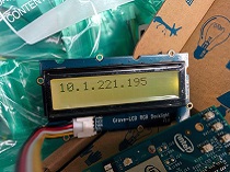
| Edison Wi-Fi 地址 | WiFi 智能温室 | Grove 幸运饺子 |
|---|---|---|
|
|
|
| 立即制作! | 立即制作! | 立即制作! |
| 刷牙指导器 | LinkIt ONE Pager | LinkIt ONE IoT 演示 |
|---|---|---|
|
|
|
| 立即制作! | 立即制作! | 立即制作! |
入门指南
如果这是您第一次使用 Arduino,我们强烈建议您在开始之前查看 Arduino 入门指南。
使用 Arduino
硬件
- 步骤 1. 准备以下物品:
| Seeeduino V4.2 | Base Shield | Grove-LCD RGB 背光 |
|---|---|---|
|
|
|
| 立即购买 | 立即购买 | 立即购买 |
- 步骤 2. 将 Grove-LCD RGB 背光连接到 Grove-Base Shield 的 I2C 端口。
- 步骤 3. 将 Grove-Base Shield 插入 Seeeduino。
- 步骤 4. 使用 USB 数据线将 Seeeduino 连接到电脑。

如果没有 Grove Base Shield,我们也可以直接将 Grove-LCD RGB 背光连接到 Seeeduino,如下所示。
| Seeeduino | Grove-LCD RGB 背光 |
|---|---|
| 5V | 红色 |
| GND | 黑色 |
| SDA | 白色 |
| SCL | 黄色 |
软件
-
步骤 1. 从 Github 下载 Grove-LCD RGB 背光库。
-
步骤 2. 参考 如何安装库 为 Arduino 安装库。
-
步骤 3. 库中包含以下 12 个示例:
- Autoscroll
- Blink
- Cursor
- CustomCharacter
- Display
- fade
- HelloWorld
- Scroll
- SerialDisplay
- setColor
- setCursor
- TextDirection
-
步骤 4. 请按照下图选择示例 HelloWorld 并上传到 Arduino。如果您不知道如何上传代码,请查看 如何上传代码。

以下是 HelloWorld.ino 的代码:
#include <Wire.h>
#include "rgb_lcd.h"

rgb_lcd lcd;

const int colorR = 255;
const int colorG = 0;
const int colorB = 0;

void setup()
{
    // 设置 LCD 的列数和行数:
    lcd.begin(16, 2);

    lcd.setRGB(colorR, colorG, colorB);

    // 在 LCD 上打印消息。
    lcd.print("hello, world!");

    delay(1000);
}

void loop()
{
    // 将光标设置到第 0 列,第 1 行
    // (注意:第 1 行是第二行,因为计数从 0 开始):
    lcd.setCursor(0, 1);
    // 打印自复位以来的秒数:
    lcd.print(millis()/1000);

    delay(100);
}
- 步骤 5. 我们将在 LCD 上看到 "hello, world"。
使用 Codecraft
硬件
步骤 1. 使用 Grove 电缆将 Grove-LCD RGB 背光连接到 Seeeduino 的 I2C 端口。如果您使用的是 Arduino,请使用 Base Shield。
步骤 2. 使用 USB 数据线将 Seeeduino/Arduino 连接到电脑。
软件
步骤 1. 打开 Codecraft,添加 Arduino 支持,并将主程序拖到工作区。
如果这是您第一次使用 Codecraft,请参阅 Codecraft 使用 Arduino 指南。
步骤 2. 按下图拖动模块或打开页面底部提供的 cdc 文件。

将程序上传到您的 Arduino/Seeeduino。
当代码上传完成后,您将在 LCD 上看到 "hello, world!" 和系统运行时间。
使用 Raspberry Pi
硬件
- 步骤 1. 准备以下物品:
| Raspberry Pi | GrovePi_Plus | Grove-LCD RGB 背光 |
|---|---|---|
|
|
|
| 立即购买 | 立即购买 | 立即购买 |
- 步骤 2. 将 GrovePi_Plus 插入 Raspberry Pi。
- 步骤 3. 将 Grove-LCD RGB 背光连接到 GrovePi_Plus 的 I2C 端口。
- 步骤 4. 使用 USB 数据线将 Raspberry Pi 连接到电脑。

软件
如果您使用的是 Raspberry Pi 且 Raspberry Pi OS >= Bullseye,您必须仅使用 Python3 执行以下命令行。
- 步骤 1. 按照 设置软件 配置开发环境。
- 步骤 2. Git 克隆 Github 仓库。
cd ~
git clone https://github.com/DexterInd/GrovePi.git
- 步骤 3. 执行以下命令,使用 Grove-LCD RGB 背光显示。
cd ~/GrovePi/Software/Python/grove_rgb_lcd
python3 grove_rgb_lcd.py
以下是 grove_rgb_lcd.py 的代码。
import time,sys

if sys.platform == 'uwp':
    import winrt_smbus as smbus
    bus = smbus.SMBus(1)
else:
    import smbus
    import RPi.GPIO as GPIO
    rev = GPIO.RPI_REVISION
    if rev == 2 or rev == 3:
        bus = smbus.SMBus(1)
    else:
        bus = smbus.SMBus(0)

# 该设备有两个 I2C 地址
DISPLAY_RGB_ADDR = 0x62
DISPLAY_TEXT_ADDR = 0x3e

# 设置背光颜色为 (R,G,B) (每个值范围为 0..255)
def setRGB(r,g,b):
    bus.write_byte_data(DISPLAY_RGB_ADDR,0,0)
    bus.write_byte_data(DISPLAY_RGB_ADDR,1,0)
    bus.write_byte_data(DISPLAY_RGB_ADDR,0x08,0xaa)
    bus.write_byte_data(DISPLAY_RGB_ADDR,4,r)
    bus.write_byte_data(DISPLAY_RGB_ADDR,3,g)
    bus.write_byte_data(DISPLAY_RGB_ADDR,2,b)

# 发送命令到显示屏 (无需外部使用)
def textCommand(cmd):
    bus.write_byte_data(DISPLAY_TEXT_ADDR,0x80,cmd)

# 设置显示文本 \n 表示第二行(或自动换行)
def setText(text):
    textCommand(0x01) # 清除显示
    time.sleep(.05)
    textCommand(0x08 | 0x04) # 打开显示,无光标
    textCommand(0x28) # 两行显示
    time.sleep(.05)
    count = 0
    row = 0
    for c in text:
        if c == '\n' or count == 16:
            count = 0
            row += 1
            if row == 2:
                break
            textCommand(0xc0)
            if c == '\n':
                continue
        count += 1
        bus.write_byte_data(DISPLAY_TEXT_ADDR,0x40,ord(c))

# 更新显示内容而不清除显示
def setText_norefresh(text):
    textCommand(0x02) # 返回首页
    time.sleep(.05)
    textCommand(0x08 | 0x04) # 打开显示,无光标
    textCommand(0x28) # 两行显示
    time.sleep(.05)
    count = 0
    row = 0
    while len(text) < 32: # 清除屏幕剩余部分
        text += ' '
    for c in text:
        if c == '\n' or count == 16:
            count = 0
            row += 1
            if row == 2:
                break
            textCommand(0xc0)
            if c == '\n':
                continue
        count += 1
        bus.write_byte_data(DISPLAY_TEXT_ADDR,0x40,ord(c))

# 示例代码
if __name__=="__main__":
    setText("Hello world\nThis is an LCD test")
    setRGB(0,128,64)
    time.sleep(2)
    for c in range(0,255):
        setText_norefresh("Going to sleep in {}...".format(str(c)))
        setRGB(c,255-c,0)
        time.sleep(0.1)
    setRGB(0,255,0)
    setText("Bye bye, this should wrap onto next line")
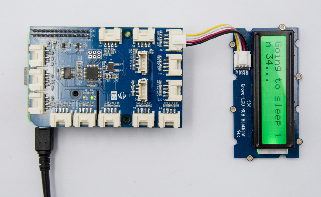
- 步骤 4. 我们将看到 Grove-LCD RGB 背光显示内容为 Going to sleep in 1...
常见问题
-
问题 1: 如何使用多个 Grove-LCD RGB 背光?
- 答案 1: 请参考 Arduino 软件 I2C 用户指南。
-
问题 2: 如何使用按钮切换 Grove RGB LCD 显示不同页面?
- 答案 2: 以下是代码。
#include <Wire.h>
#include "rgb_lcd.h"

rgb_lcd lcd;
const int switchPin = 2;
static int hits = 0;
int switchState = 0;
int prevSwitchState = 0;

void setup() {
    lcd.begin(16, 2);
    pinMode(switchPin,INPUT);
    Serial.begin(9600);
    lcd.setCursor(0, 0);
    lcd.print("Page 1");
}

void loop() {
  switchState = digitalRead(switchPin);
  Serial.print("switchState:");Serial.println(switchState);
  if (switchState != prevSwitchState) {
    if (switchState == HIGH) {
          hits = hits + 1;
          delay(10);
    }
  }

  Serial.print("hits:");Serial.println(hits);
  if(hits==1)
  {
    Serial.println("Page 1");
    lcd.clear();
    lcd.setCursor(0, 0);
    lcd.print("Page 1");
  }else
  if(hits==2)
  {
   Serial.println("Page 2");
    lcd.clear();
    lcd.setCursor(0, 0);
    lcd.print("Page 2");
  }else

  if(hits==3)
  {
   Serial.println("Page 3");
    lcd.clear();
    lcd.setCursor(0, 0);
    lcd.print("Page 3");
  }else

  if ( hits>=4)
  {
     hits = 0;
     Serial.println("couter is reset");
     Serial.println("Page 1");
     lcd.clear();
     lcd.setCursor(0, 0);
     lcd.print("Page 1");
  }
delay(500);
}
资源
- [库] 软件库
- [文档] 此文档的 Github 页面
- [Codecraft] CDC 文件
- [数据手册] PCA9633
- [数据手册] JHD1313
项目
Particle + Grove LCD RGB 背光 = 实时时钟:使用 I2C 将 Grove LCD RGB 背光连接到 Particle,以显示时间。
LCD RGB Grove 模块:
技术支持与产品讨论
感谢您选择我们的产品!我们致力于为您提供多种支持,以确保您使用我们的产品时体验顺畅。我们提供多种沟通渠道,以满足不同的偏好和需求。


