Grove - 旋转角度传感器
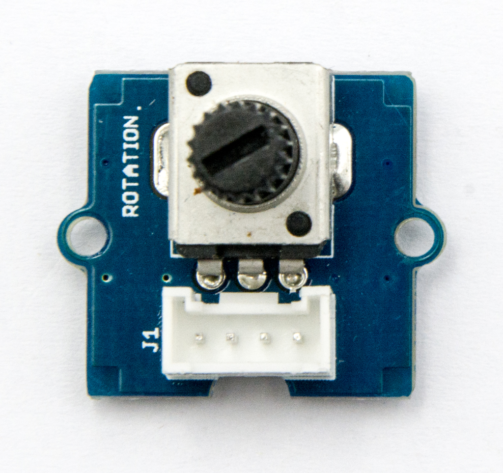
旋转角度传感器在其 D1 接口上输出 0 到 Vcc(在 Seeeduino 上为 5V 直流电)之间的模拟信号。D2 接口未使用。角度范围为 300 度,输出值线性变化。电阻值为 10k 欧姆,非常适合 Arduino 使用。这种器件也被称为“电位器(potentiometer)”。

还有另一款产品,Grove - Rotary Angle Sensor(P)。 “P” 是什么意思?在这款产品中,“P” 代表“面板安装(panel mount)”。它是 Grove - Rotary Angle Sensor 的姊妹版本。两者完全相同,只是 Grove 接插件被移到了背面,这样你就可以轻松地将其作为一个整洁且无线的人机交互设备来使用。
 |  |
版本
| 产品版本 | 变更说明 | 发布日期 |
|---|---|---|
| Grove-Rotary Angle Sensor(P) V1.1 | 初始版本 | 2013 年 1 月 |
| Grove-Rotary Angle Sensor V1.2 | 初始版本 | 2014 年 5 月 |
特性
- Grove 接口
- 易于使用
- Grove 基础模块
关于 Grove 模块的更多细节请参考 Grove System
规格参数
| 项目 | 最小 | 典型 | 最大 | 单位 |
|---|---|---|---|---|
| 电压 | 4.75 | 5.0 | 5.25 | VDC |
| 旋转角度 | 0 | / | 300 | 度 |
| 尺寸 | / | 19x19x30.1 | / | mm |
支持的平台
| Arduino | Raspberry Pi | |||
|---|---|---|---|---|
 |  |  |  |  |
上面提到的受支持平台仅表示该模块在软件或理论上的兼容性。在大多数情况下,我们只为 Arduino 平台提供软件库或代码示例。不可能为所有可能的 MCU 平台都提供软件库或演示代码。因此,用户需要自行编写软件库。
入门指南
如果这是你第一次使用 Arduino,我们强烈建议你在开始之前先阅读 Getting Started with Arduino。
使用 Arduino 玩一玩
硬件
- 步骤 1. 准备以下物品:
| Seeeduino V4.2 | Base Shield | Grove-Rotary Angle Sensor | Grove-LED |
|---|---|---|---|
 |  |  |  |
| 立即获取 | 立即获取 | 立即获取 | 立即获取 |
- 步骤 2. 将 Grove-Rotary Angle Sensor 连接到 Grove-Base Shield 的 A0 端口。
- 步骤 3. 将 Grove-LED 连接到 Grove-Base Shield 的 D3 端口。
- 步骤 4. 将 Grove - Base Shield 插到 Seeeduino 上。
- 步骤 5. 通过 USB 线将 Seeeduino 连接到电脑。

如果我们没有 Grove Base Shield,也可以像下面这样将 Grove-Rotary Angle Sensor 和 Grove-Led 直接连接到 Seeeduino。Grove-Led 必须连接到 PWM 端口。对于 Seeeduino,它们是 D3、5、6、9、10、11。
| Seeeduino | Grove-Rotary Angle Sensor | Seeeduino | Grove-LED |
|---|---|---|---|
| 5V | Red | 5V | Red |
| GND | Black | GND | Black |
| NC | White | NC | White |
| A0 | Yellow | D3 | Yellow |
软件
- 步骤 1. 请将下面的代码复制到 Arduio IDE 中并上传到 Arduino。如果你不知道如何上传代码,请查看如何上传代码。
/*macro definitions of Rotary angle sensor and LED pin*/

#define ROTARY_ANGLE_SENSOR A0
#define LED 3  //the Grove - LED is connected to PWM pin D3 of Arduino
#define ADC_REF 5 //reference voltage of ADC is 5v.If the Vcc switch on the seeeduino
                    //board switches to 3V3, the ADC_REF should be 3.3
#define GROVE_VCC 5 //VCC of the grove interface is normally 5v
#define FULL_ANGLE 300 //full value of the rotary angle is 300 degrees

void setup()
{
    Serial.begin(9600);
    pinMode(ROTARY_ANGLE_SENSOR, INPUT);
    pinMode(LED,OUTPUT);
}

void loop()
{
    float voltage;
    int sensor_value = analogRead(ROTARY_ANGLE_SENSOR);
    voltage = (float)sensor_value*ADC_REF/1023;
    float degrees = (voltage*FULL_ANGLE)/GROVE_VCC;
    Serial.println("The angle between the mark and the starting position:");
    Serial.println(degrees);

    int brightness;
    brightness = map(degrees, 0, FULL_ANGLE, 0, 255);
    analogWrite(LED,brightness);
    delay(500);
}
- 步骤 2. 调节 Grove-Rotary Angle Sensor,我们会看到 Grove-LED 的亮度发生变化。
使用 Codecraft 玩一玩
硬件
步骤 1. 将一个 Grove - Rotary Angle Sensor 连接到 A0 端口,将一个 Grove - Red LED 连接到 Base Shield 的 D3 端口。
步骤 2. 将 Base Shield 插到你的 Seeeduino/Arduino 上。
步骤 3. 通过 USB 线将 Seeeduino/Arduino 连接到电脑。
软件
步骤 1. 打开 Codecraft,添加 Arduino 支持,并拖拽一个主程序到工作区。
如果这是你第一次使用 Codecraft,请同时参考在 Arduino 上使用 Codecraft 的指南。
步骤 2. 按下图拖拽积木块,或者打开本页末尾可下载的 cdc 文件。

将程序上传到你的 Arduino/Seeeduino。
当代码上传完成后,LED 的亮度会根据传感器的角度而变化,角度值会显示在串口监视器中。
使用 Raspberry Pi 玩一玩(搭配 Grove Base Hat for Raspberry Pi)
硬件
- 步骤 1. 本项目中使用的器件:
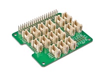
| Raspberry pi | Grove Base Hat for RasPi | Grove - Rotary Angle Sensor |
|---|---|---|
 |  | |
| 立即获取 | 立即获取 | 立即获取 |
- 步骤 2. 将 Grove Base Hat 插到 Raspberry 上。
- 步骤 3. 将旋转传感器连接到 Base Hat 的 A0 端口。
- 步骤 4. 通过 USB 线将 Raspberry Pi 连接到电脑。

在步骤 3 中,你也可以将旋转角度传感器连接到任意模拟端口,但请确保将命令中的端口号改为对应的端口。
软件
如果你使用的是 搭载 Raspberrypi OS >= Bullseye 的 Raspberry Pi,你必须只在 Python3 下使用这条命令行。
- 步骤 1. 按照 Setting Software 配置开发环境。
- 步骤 2. 通过克隆 grove.py 库来下载源文件。
cd ~
git clone https://github.com/Seeed-Studio/grove.py
- 步骤 3. 执行以下命令来运行代码。
cd grove.py/grove
python3 grove_rotary_angle_sensor.py 0
下面是 grove_rotary_angle_sensor.py 代码。
import math
import sys
import time
from grove.adc import ADC


class GroveRotaryAngleSensor(ADC):
    def __init__(self, channel):
        self.channel = channel
        self.adc = ADC()

    @property
    def value(self):
        return self.adc.read(self.channel)


Grove = GroveRotaryAngleSensor


def main():
    if len(sys.argv) < 2:
        print('Usage: {} adc_channel'.format(sys.argv[0]))
        sys.exit(1)

    sensor = GroveRotaryAngleSensor(int(sys.argv[1]))

    while True:
        print('Rotary Value: {}'.format(sensor.value))
        time.sleep(.2)


if __name__ == '__main__':
    main()
如果一切顺利,你将能够看到如下结果
pi@raspberrypi:~/grove.py/grove $ python3 grove_rotary_angle_sensor.py 0
Rotary Value: 932
Rotary Value: 931
Rotary Value: 931
Rotary Value: 931
Rotary Value: 933
Rotary Value: 931
Rotary Value: 742
Rotary Value: 666
Rotary Value: 666
Rotary Value: 549
Rotary Value: 520
Rotary Value: 499
Rotary Value: 430
Rotary Value: 430
Rotary Value: 321
Rotary Value: 286
Rotary Value: 205
Rotary Value: 127
Rotary Value: 88
Rotary Value: 0
Rotary Value: 0
Rotary Value: 0
Rotary Value: 0
Rotary Value: 0
Rotary Value: 0
Rotary Value: 0
^CTraceback (most recent call last):
  File "grove_rotary_angle_sensor.py", line 66, in <module>
    main()
  File "grove_rotary_angle_sensor.py", line 62, in main
    time.sleep(.2)
KeyboardInterrupt
你可以通过按 ++ctrl+c++ 来退出该程序。
你可能已经注意到,对于模拟端口,丝印引脚编号类似 A0, A1,然而在命令中我们使用参数 0 和 1,与数字端口相同。所以请确保你将模块插入正确的端口,否则可能会出现引脚冲突。
使用 Raspberry Pi(搭配 GrovePi_Plus)玩一玩
硬件
- 步骤 1. 准备以下物品:
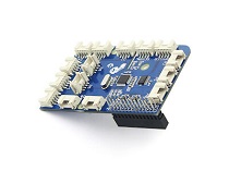
| Raspberry pi | GrovePi_Plus | Grove-Rotary Angle Sensor | Grove-LED |
|---|---|---|---|
|  | | |
| Get ONE Now | Get ONE Now | 立即获取 | 立即获取 |
- 步骤 2. 将 GrovePi_Plus 插到 Raspberry 上。
- 步骤 3. 将 Grove-Rotary Angle Sensor 连接到 GrovePi_Plus 的 A0 端口。
- 步骤 4. 将 Grove-LED 连接到 GrovePi_Plus 的 D5 端口。
- 步骤 5. 通过 USB 线将 Raspberry 连接到电脑。

软件
如果你使用的是 搭载 Raspberrypi OS >= Bullseye 的 Raspberry Pi,你必须只使用 Python3 来运行这条命令行。
- 步骤 1. 按照 Setting Software 配置开发环境。
- 步骤 2. Git 克隆 Github 仓库。
cd ~
git clone https://github.com/DexterInd/GrovePi.git
- 步骤 3. 执行以下命令来监测响度。
cd ~/GrovePi/Software/Python
python3 grove_rotary_angle_sensor.py
下面是 grove_rotary_angle_sensor.py 代码。
import time
import grovepi

# Connect the Grove Rotary Angle Sensor to analog port A0
# SIG,NC,VCC,GND
potentiometer = 0

# Connect the LED to digital port D5
# SIG,NC,VCC,GND
led = 5

grovepi.pinMode(potentiometer,"INPUT")
grovepi.pinMode(led,"OUTPUT")
time.sleep(1)

# Reference voltage of ADC is 5v
adc_ref = 5

# Vcc of the grove interface is normally 5v
grove_vcc = 5

# Full value of the rotary angle is 300 degrees, as per it's specs (0 to 300)
full_angle = 300

while True:
    try:
        # Read sensor value from potentiometer
        sensor_value = grovepi.analogRead(potentiometer)

        # Calculate voltage
        voltage = round((float)(sensor_value) * adc_ref / 1023, 2)

        # Calculate rotation in degrees (0 to 300)
        degrees = round((voltage * full_angle) / grove_vcc, 2)

        # Calculate LED brightess (0 to 255) from degrees (0 to 300)
        brightness = int(degrees / full_angle * 255)

        # Give PWM output to LED
        grovepi.analogWrite(led,brightness)

        print("sensor_value = %d voltage = %.2f degrees = %.1f brightness = %d" %(sensor_value, voltage, degrees, brightness))
    except KeyboardInterrupt:
        grovepi.analogWrite(led,0)
        break
    except IOError:
        print ("Error")
- 步骤 4. 调节 Grove-Rotary Angle Sensor,我们将看到 Grove-LED 的亮度发生变化。
使用 TI LaunchPad 玩一玩
读取电位器(旋转角度传感器)
本示例展示如何读取来自 Grove 电位器模块的模拟输出。在这个示例中我们将组合使用几个 Grove 模块!通过旋转电位器旋钮,我们将在 Grove 4 位数码管上显示模拟读数值。

/*
    Rotary Angle Sensor
    Demonstrates analog input by reading an analog sensor on J16 of the Grove Base BoosterPack. The speed of the red LED on the LaunchPad will change depending on the position of the potentiometer knob. This example will also display the analog reading value on the Grove 4-digital display.

    The circuit:
    * Potentiometer attached to pin 24 (J6 on Grove Base BoosterPack)
    * center pin of the potentiometer to the analog pin
    * one side pin (either one) to ground
    * the other side pin to VCC (3.3V)

    * Note: Because of unstable of the voltage, the value of the rotary angle sensor
            varies slightly from run to run even you don't touch it.

    Created by Oliver Wang

    This example code is in the public domain.

    https://www.seeedstudio.com/wiki/GROVE_-_Starter_Kit_v1.1b#Grove_-_Rotary_Angle_Sensor
    */

#include "TM1637.h"

/* Macro Define */
#define CLK               39                  /* 4-digital display clock pin */
#define DIO               38                /* 4-digital display data pin */
#define ROTARY_ANGLE_P    24               /* pin of rotary angle sensor */

/* Global Variables */
TM1637 tm1637(CLK, DIO);                  /* 4-digital display object */
int analog_value = 0;                     /* variable to store the value coming from rotary angle sensor */

int8_t bits[4] = {0};                     /* array to store the single bits of the value */

/* the setup() method runs once, when the sketch starts */
void setup() {

    /* Initialize 4-digital display */
    tm1637.init();
    tm1637.set(BRIGHT_TYPICAL);

}

/* the loop() method runs over and over again */
void loop() {

    analog_value = analogRead(ROTARY_ANGLE_P);      /* read the value from the sensor */
    memset(bits, 0, 4);                             /* reset array when we use it */
    for(int i = 3; i >= 0; i--) {
        /* get single bits of the analog value */
        bits[i] = analog_value % 10;
        analog_value = analog_value / 10;
        tm1637.display(i, bits[i]);                 /* display by 4-digital display */
    }
    delay(100);
}
Grove - Rotary Angle Sensor(P) v1.1 原理图文件
Grove-Rotary Angle Sensor v1.2 原理图文件
资源
- [Eagle&PDF] Grove-Rotary Angle Sensor v1.2 原理图文件
- [Eagle&PDF] Grove - Rotary Angle Sensor(P) v1.1 原理图文件
- [Library] Rotary Angle Sensor 的 Github 仓库
- [Codecraft] CDC 文件
项目
使用 Grove-Rotary Angle Sensor(P) 控制 Grove LED:使用 Arduino/Genuino 101 通过 Grove-Rotary Angle Sensor(P) 控制 LED 的亮度。
旋转角度 Grove 模块:
技术支持与产品讨论
感谢您选择我们的产品!我们将为您提供多种支持,确保您在使用我们产品的过程中尽可能顺畅。我们提供多种沟通渠道,以满足不同的偏好和需求。