单通道 LoRaWAN 网关 - SenseCAP Indicator
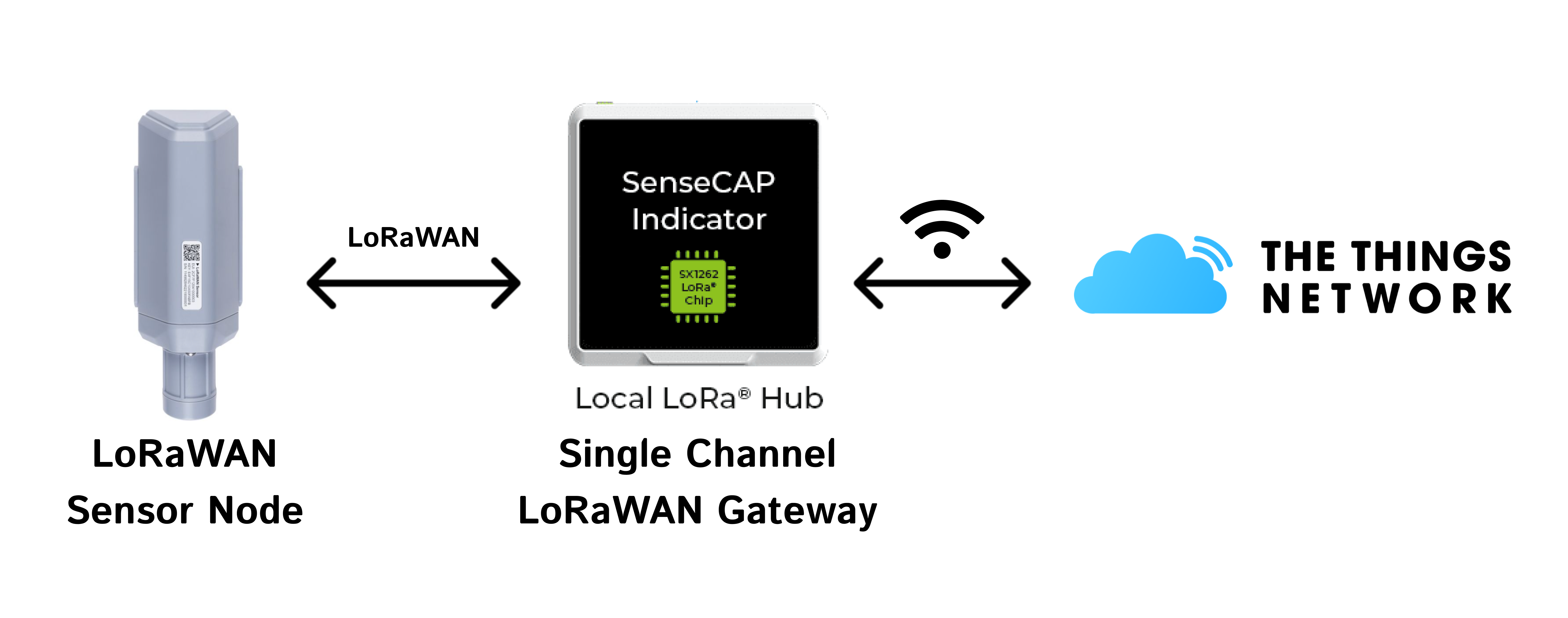

这个项目演示了如何使用 SenseCAP Indicator 实现单通道 LoRaWAN 网关(LoRaHub),该设备使用 ESP32S3 作为主控 MCU 和 SX1262 LoRa 无线电,并在 The Things Network(TTN)上构建 LoRaWAN 应用程序。升级固件为那些有兴趣深入研究 LoRa 技术并建立与 LNS(LoRa 网络服务器)连接的用户提供了实用的解决方案。
对于单通道网关(称为单通道集线器),这些是低成本工具,使用户能够开始探索 LoRa 领域。这些网关可以在特定的扩频因子和通道上接收 LoRa 数据包,并促进这些数据包与网络的交换。由于其经济实惠,许多用户已经开始构建自己的单通道网关来试验 LoRa。
这是 GitHub 项目:SenseCAP Indicator LoRaHub 演示。
烧录固件
固件已准备好安装。只需从 bin 库 下载最新版本。
我们还在 GitHub 中提供了合并版本的固件。以下说明基于分离版本,便于初学者理解。如果您想直接烧录合并版本,请将烧录地址设置为 0x0。
如果您不使用完整的 ESP-IDF 环境,也可以使用 esptool 实用程序烧录提供的二进制文件。
点击下载固件:
自定义和构建固件
如果您想重置配置,以下说明可以帮助您在 ESP-IDF 环境下自行构建固件。
设置环境
此项目基于 Espressif ESP-IDF 开发,请查看此指南来设置环境。
获取 ESP-IDF
mkdir -p ~/esp
cd ~/esp
git clone -b v5.2.1 --recursive https://github.com/espressif/esp-idf.git
设置工具
cd esp-idf/
./install.sh
一个通道集线器的安装
步骤 1: 将仓库克隆到本地仓库。并导航到项目路径。
git clone https://github.com/Seeed-Solution/SenseCAP_Indicator_ESP32.git

cd ~/this_project_directory/
步骤 2:安装所需驱动
- 获取无线电驱动程序:
cd ~/this_project_directory/components/radio_drivers
- SX126x 驱动程序(sx1261, sx1262, sx1268):
git clone -b v2.3.2 https://github.com/Lora-net/sx126x_driver.git sx126x_driver
- llcc68 驱动程序:
git clone -b v2.3.2 https://github.com/Lora-net/llcc68_driver.git llcc68_driver
- lr11xx 驱动程序(lr1121):
git clone -b v2.4.1 https://github.com/Lora-net/SWDR001.git lr11xx_driver
构建固件
步骤 1: 进入 lorahub 目录。
cd ~/this_project_directory/lorahub
为从命令行使用 ESP-IDF 进行构建准备您的 Linux/MAC 终端。在 Windows 上可以跳过此步骤,因为已安装的 'ESP-IDF x.x CMD' 工具会自动准备环境。
. ~/esp/esp-idf/export.sh
配置要构建的 ESP32 目标。
idf.py set-target esp32s3
如有必要,自定义构建:
idf.py menuconfig
构建项目:
idf.py all
使用 esp-idf 刷写固件
识别要刷写固件的单通道集线器关联的串行设备。 对于 linux 和 mac,可以通过以下方式检查串行端口
ls /dev/cu*
然后使用 idf.py 进行刷写,替换 端口
idf.py -p port flash
如果返回权限错误,请检查当前用户是否属于 dialout 组。如果不是,请执行以下操作,重启 Linux 机器并重试:
sudo usermod -a -G dialout $USERNAME
在 Windows 设置中,假设设备挂载为 COM14,上述命令将类似于:
idf.py -p COM14 flash
启动监视控制台以查看日志(可选)。
idf.py -p port monitor
使用 esptool 烧录
如果不使用完整的 ESP-IDF 环境,也可以使用 esptool 工具烧录提供的二进制文件。
https://docs.espressif.com/projects/esptool/en/latest/esp32/
// Merged version
esptool.py --chip esp32s3 -p port -b 460800 --before=default_reset --after=hard_reset write_flash --flash_mode dio --flash_freq 80m --flash_size 8MB 0x0 Indicator_Lorahub_v1.0.0.bin
// Seperated version
esptool.py --chip esp32s3 -p port -b 460800 --before=default_reset --after=hard_reset write_flash --flash_mode dio --flash_freq 80m --flash_size 8MB 0x0 bootloader.bin 0x10000 indicator_lorahub.bin 0x8000 partition-table.bin
在 Windows 环境下,用于刷写固件的 esptool 命令应该是:
// Merged version
py -m esptool --chip esp32s3 -p COM -b 460800 --before=default_reset --after=hard_reset write_flash --flash_mode dio --flash_freq 80m --flash_size 8MB 0x0 Indicator_Lorahub_v1.0.0.bin
// Seperated version
py -m esptool --chip esp32s3 -p COM -b 460800 --before=default_reset --after=hard_reset write_flash --flash_mode dio --flash_freq 80m --flash_size 8MB 0x0 bootloader.bin 0x10000 indicator_lorahub.bin 0x8000 partition-table.bin
将 port 和 COM 替换为所使用的串口名称。如果连接失败,请参阅故障排除。
使用 esptool-JS 烧录
推荐使用在线 esptool 进行烧录。
步骤1:将波特率设置为 115200 并连接到正确的端口。
步骤2:选择 bin 文件并填入相应的烧录地址。
- 合并版本:
| 烧录地址 | 文件 |
|---|---|
| 0x0 | Indicator_Lorahub_v1.0.0.bin |
- 分离版本:
| Flash 地址 | 文件 |
|---|---|
| 0x0 | bootloader.bin |
| 0x10000 | indicator_lorahub.bin |
| 0x8000 | partition-table.bin |
Indicator 配置
步骤1. 进入 Wi-Fi 页面配置网络,选择合适的 SSID,并输入密码。
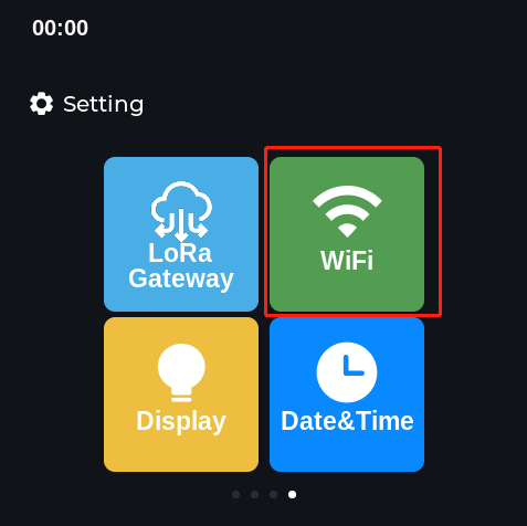
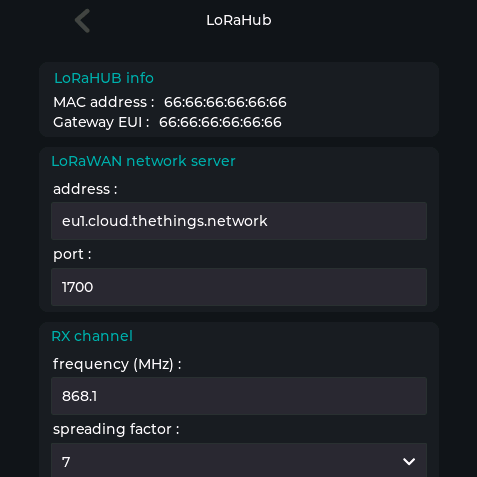
步骤2. 在 LoRa Gateway 页面配置参数,将 LNS 和端口设置为 "1700",点击 "configure",然后点击 "reboot"。

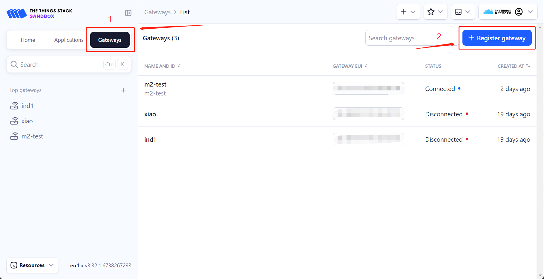
连接到 The Things Network(TTN)
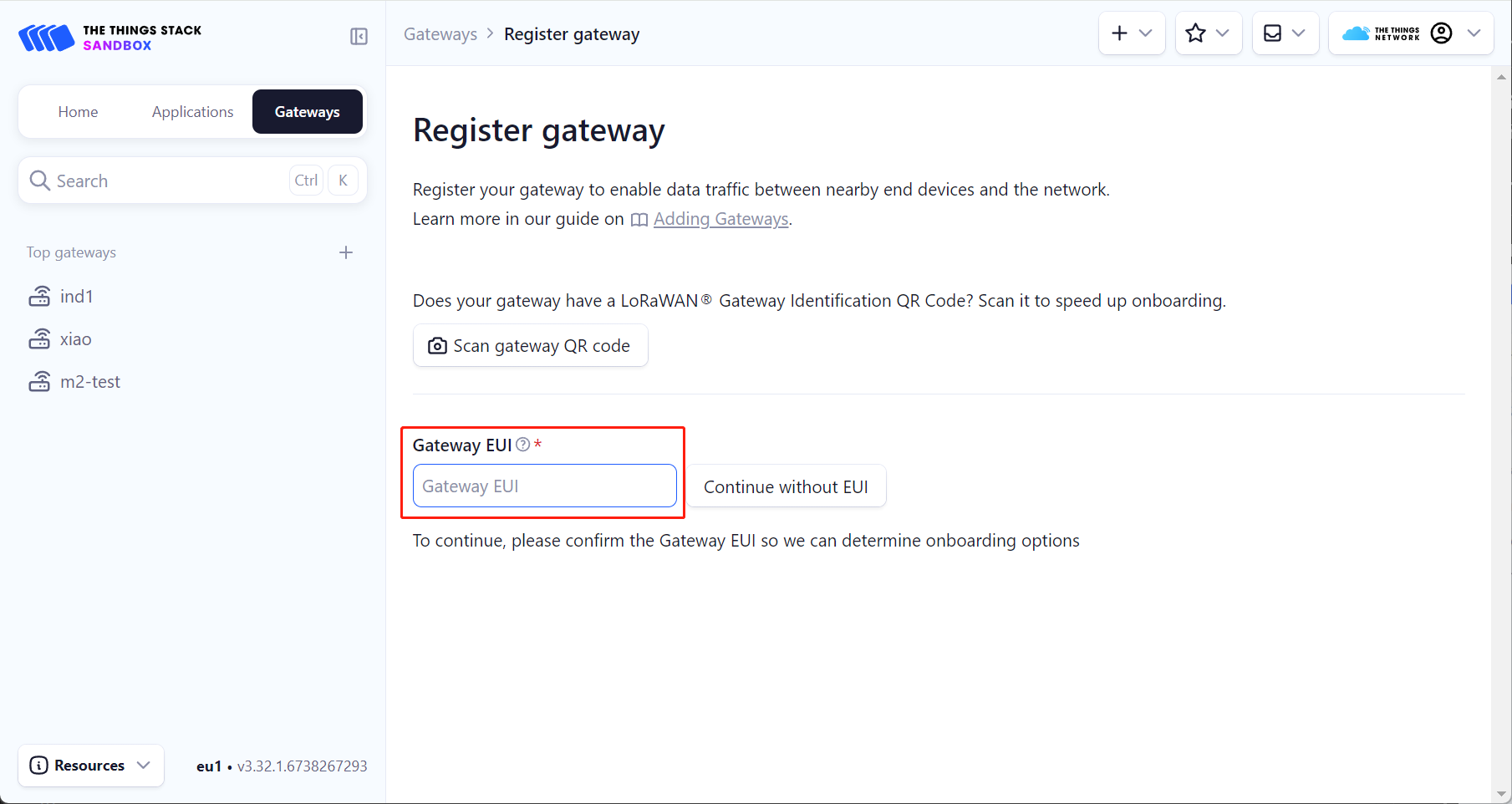
步骤 1: 登录 TTN 平台并进入 console,点击 Gateways->Register gateway。
步骤 2: 将 Indicator 的 Gateway ID 输入到 Gateway EUI 中。
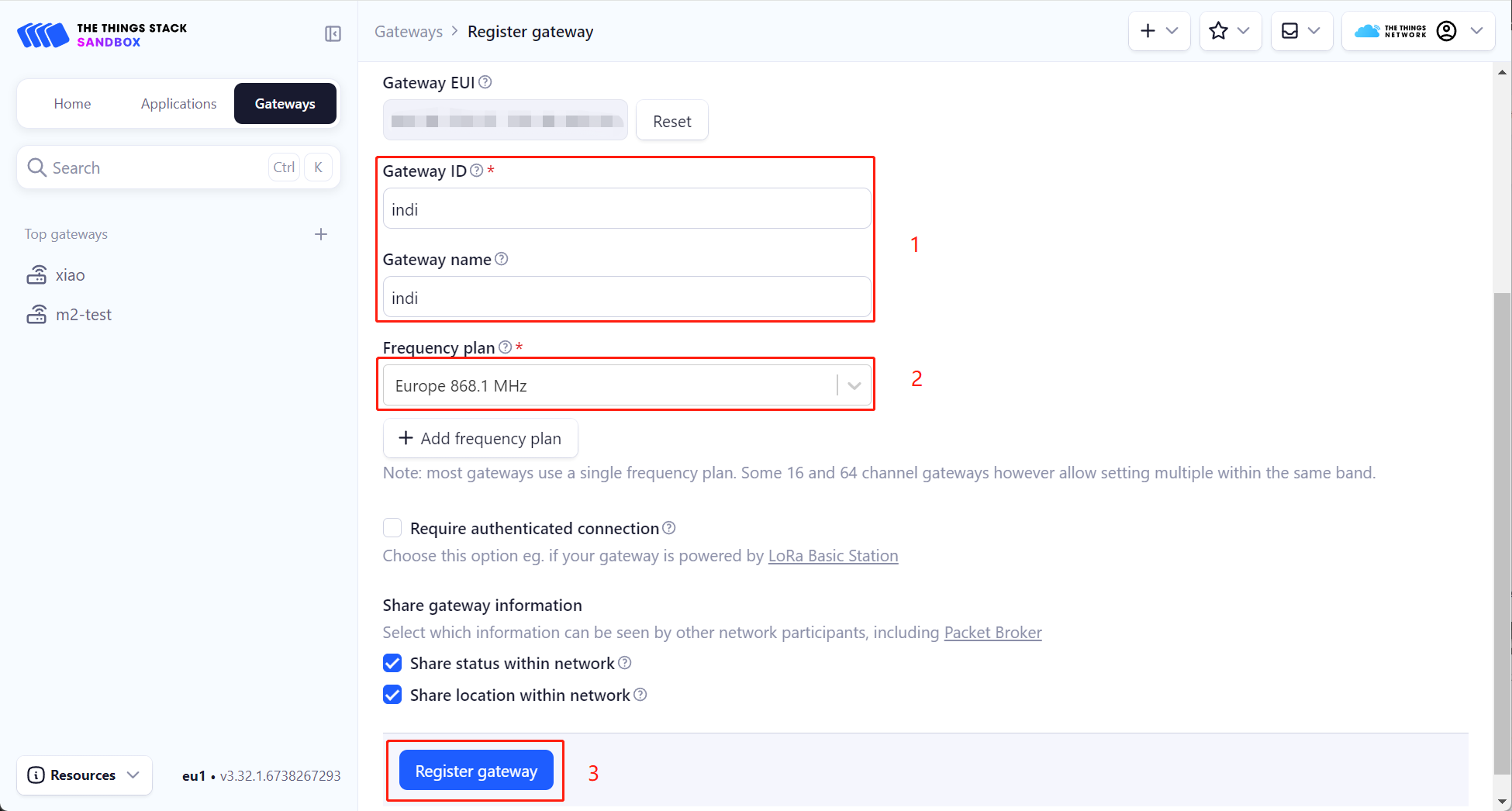
步骤 3: 填写自定义网关名称后,选择相应的频率计划(必须与 Indicator 上的配置匹配),然后点击 Register gateway。此时,Indicator 的单通道网关已添加到 TTN。
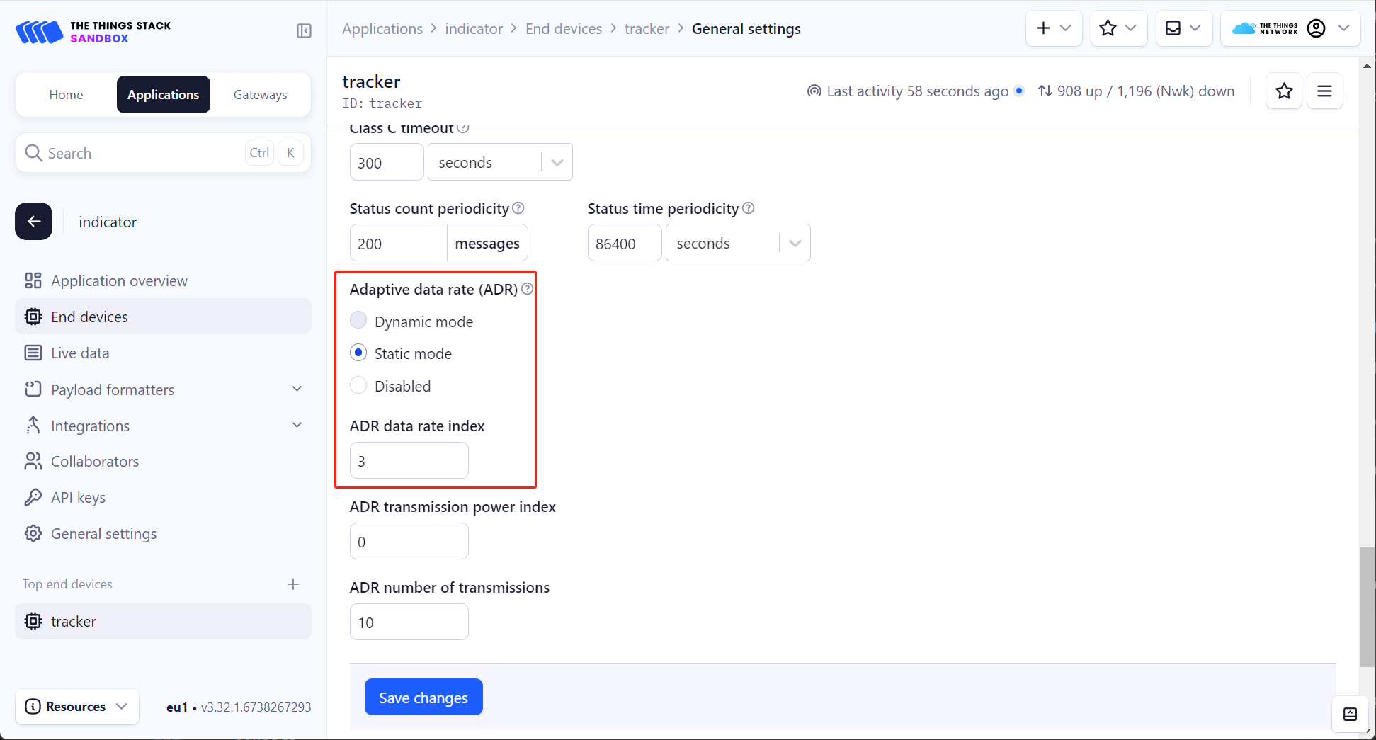
步骤 4: 添加 Indicator 单通道网关后,点击 Applications 添加设备。在此示例中,使用 SenseCAP T1000 Tracker 作为节点设备。详细连接步骤请参考 Wiki:https://wiki.seeedstudio.com/SenseCAP_T1000_tracker_TTN/。在 End devices->General settings->Network layer->Advanced MAC settings 中,您需要将 Adaptive data rate (ADR) 设置为 Static mode,并且 ADR data rate index 需要根据 Indicator 上设置的 spreading factor 进行配置。例如,如果 spreading factor 设置为 9,则 ADR data rate index 应设置为 3,其他值同理。
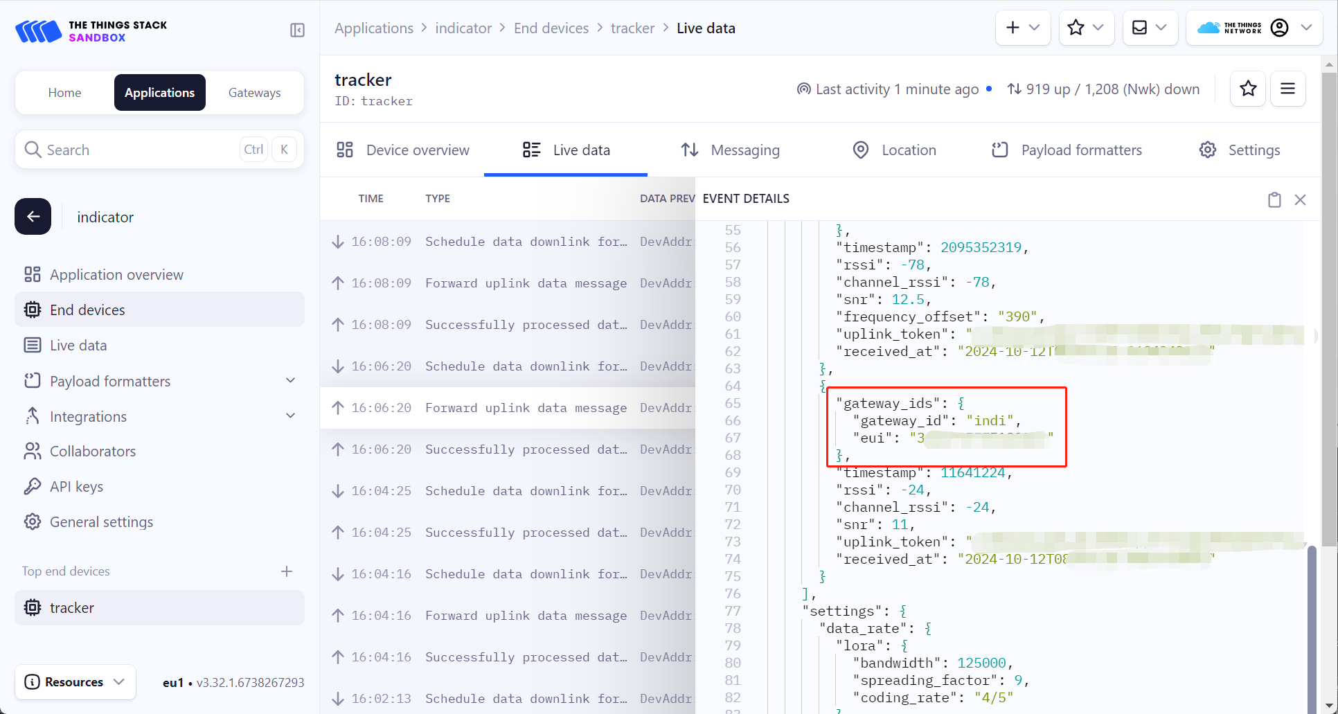
步骤 5: 如下所示,您可以在添加的节点设备的 Live data 中查看 EVENT DETAILS 来查看相关日志。您可以看到节点设备通过新添加的 Indicator 单通道网关报告数据。
连接到 ChirpStack
步骤 1: 参考 Setup ChirpStack on Ubuntu/Debian 安装 ChirpStack。
步骤 2: 安装 ChirpStack 后,您需要在 /etc/chirpstack 目录中添加单通道区域定义。
在此 Wiki 中,我们在 EU868 频段下创建单通道定义,使用 868.1Mhz 通道。
region_eu868_1ch.toml
# This file contains an example EU868 configuration.
[[regions]]

  # ID is an user-defined identifier for this region.
  id="eu868_1ch"

  # Description is a short description for this region.
  description="EU868_1CH"

  # Common-name refers to the common-name of this region as defined by
  # the LoRa Alliance.
  common_name="EU868"


  # Gateway configuration.
  [regions.gateway]

    # Force gateways as private.
    #
    # If enabled, gateways can only be used by devices under the same tenant.
    force_gws_private=false


    # Gateway backend configuration.
    [regions.gateway.backend]

      # The enabled backend type.
      enabled="mqtt"

      # MQTT configuration.
      [regions.gateway.backend.mqtt]

        # Topic prefix.
        #
        # The topic prefix can be used to define the region of the gateway.
        # Note, there is no need to add a trailing '/' to the prefix. The trailing
        # '/' is automatically added to the prefix if it is configured.
        topic_prefix="eu868"

        # MQTT server (e.g. scheme://host:port where scheme is tcp, ssl or ws)
        server="tcp://$MQTT_BROKER_HOST:1883"

        # Connect with the given username (optional)
        username=""

        # Connect with the given password (optional)
        password=""

        # Quality of service level
        #
        # 0: at most once
        # 1: at least once
        # 2: exactly once
        #
        # Note: an increase of this value will decrease the performance.
        # For more information: https://www.hivemq.com/blog/mqtt-essentials-part-6-mqtt-quality-of-service-levels
        qos=0

        # Clean session
        #
        # Set the "clean session" flag in the connect message when this client
        # connects to an MQTT broker. By setting this flag you are indicating
        # that no messages saved by the broker for this client should be delivered.
        clean_session=false

        # Client ID
        #
        # Set the client id to be used by this client when connecting to the MQTT
        # broker. A client id must be no longer than 23 characters. If left blank,
        # a random id will be generated by ChirpStack.
        client_id=""

        # Keep alive interval.
        #
        # This defines the maximum time that that should pass without communication
        # between the client and server.
        keep_alive_interval="30s"

        # CA certificate file (optional)
        #
        # Use this when setting up a secure connection (when server uses ssl://...)
        # but the certificate used by the server is not trusted by any CA certificate
        # on the server (e.g. when self generated).
        ca_cert=""

        # TLS certificate file (optional)
        tls_cert=""

        # TLS key file (optional)
        tls_key=""

  # Region specific network configuration.
  [regions.network]

    # Installation margin (dB) used by the ADR engine.
    #
    # A higher number means that the network-server will keep more margin,
    # resulting in a lower data-rate but decreasing the chance that the
    # device gets disconnected because it is unable to reach one of the
    # surrounded gateways.
    installation_margin=10

    # RX window (Class-A).
    #
    # Set this to:
    # 0: RX1 / RX2
    # 1: RX1 only
    # 2: RX2 only
    rx_window=0

    # RX1 delay (1 - 15 seconds).
    rx1_delay=1

    # RX1 data-rate offset
    rx1_dr_offset=0

    # RX2 data-rate
    rx2_dr=0

    # RX2 frequency (Hz)
    rx2_frequency=869525000

    # Prefer RX2 on RX1 data-rate less than.
    #
    # Prefer RX2 over RX1 based on the RX1 data-rate. When the RX1 data-rate
    # is smaller than the configured value, then the Network Server will
    # first try to schedule the downlink for RX2, failing that (e.g. the gateway
    # has already a payload scheduled at the RX2 timing) it will try RX1.
    rx2_prefer_on_rx1_dr_lt=0

    # Prefer RX2 on link budget.
    #
    # When the link-budget is better for RX2 than for RX1, the Network Server will first
    # try to schedule the downlink in RX2, failing that it will try RX1.
    rx2_prefer_on_link_budget=false

    # Downlink TX Power (dBm)
    #
    # When set to -1, the downlink TX Power from the configured band will
    # be used.
    #
    # Please consult the LoRaWAN Regional Parameters and local regulations
    # for valid and legal options. Note that the configured TX Power must be
    # supported by your gateway(s).
    downlink_tx_power=-1

    # ADR is disabled.
    adr_disabled=true

    # Minimum data-rate.
    min_dr=5

    # Maximum data-rate.
    max_dr=5

    # Add the following after min_dr/max_dr configuration
    enabled_uplink_channels=[0]
您也可以自定义您的单通道区域,请参阅 LoRaWAN theory for the One-Channle Hub。
步骤 3: 修改 /etc/chirpstack/chirpstack.toml 以启用新定义的区域。
enabled_regions={
  ...,
  "eu868_1ch",
  ...,
}
步骤 4: 登录 ChirpStack 控制台并添加单通道网关。
在添加网关之前,检查单通道区域是否已成功启用。

如果单通道区域成功启用,将单通道网关添加到 ChirpStack。

步骤 5: 在 LoRa 网关页面配置参数,将地址设置为您的 ChirpStack 服务器地址,点击 configure,然后点击 reboot。
重启后,您可以在 ChirpStack 控制台中看到状态变为在线。

步骤 6: 我们可以通过使用与单通道网关相同的数据速率来优化终端设备的入网时间。
参考单通道网关配置 SF7 BW125,我们将 T1000-A 的数据速率调整为 DR5。

配置 T1000-A 的数据速率后,我们需要为其创建设备配置文件。
区域选择 EU868,区域配置选择 EU868_1CH。

如下图所示,您可以看到 T1000-A 成功通过单通道网关将数据上传到 ChirpStack。

资源
技术支持与产品讨论
感谢您选择我们的产品!我们在这里为您提供不同的支持,以确保您使用我们产品的体验尽可能顺畅。我们提供多种沟通渠道,以满足不同的偏好和需求。