使用 Wio Terminal 构建红外热成像相机
概述
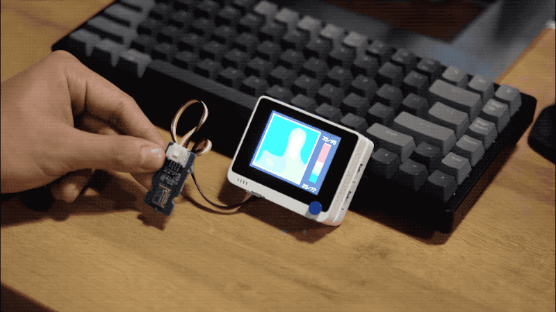
使用 Grove - 红外温度传感器阵列 (AMG8833) 和 Wio Terminal,我们可以轻松构建一个低成本的类似 FLIR™ 的热成像相机!需要说明的是,Grove - 红外温度传感器阵列 (AMG8833) 的分辨率只有 8 x 8(64 像素),在某些情况下这已经足够了。因此代码中使用了线性插值将其扩展到 70 x 70(4900 像素),以获得更好的显示效果。
这个演示受到了 Kris Kasprzak 的视频 的启发。为了使其与 Wio Terminal 和 Grove - 红外温度传感器阵列 (AMG8833) 兼容,进行了几项修改。大部分图形现在首先绘制到 TFT LCD 精灵图中,以提高整体性能和更快的帧率。还在屏幕中央添加了十字准线,并显示十字准线处的温度。
零件清单
功能特性
-
显示十字准线处的精确温度
-
红外热成像相机感应热物体
-
右按钮启用网格开/关功能
所需的 Arduino 库
-
安装 LCD 屏幕库
Seeed_Arduino_LCD,请访问 Wio Terminal LCD 获取更多信息。 -
访问 Seeed_AMG8833 仓库,将整个仓库下载到本地驱动器。
- 现在可以将 Seeed_AMG8833 库安装到 Arduino IDE 中。打开 Arduino IDE,点击
sketch->Include Library->Add .ZIP Library,选择刚刚下载的Seeed_AMG8833文件。
- 现在可以将 Seeed_AMG8833 库安装到 Arduino IDE 中。打开 Arduino IDE,点击
Arduino 说明
-
将 Grove - 红外温度传感器阵列 (AMG8833) 插入 Wio Terminal 的 Grove I2C 接口。
-
在这里下载完整代码或复制以下内容。
-
上传代码。
完整代码
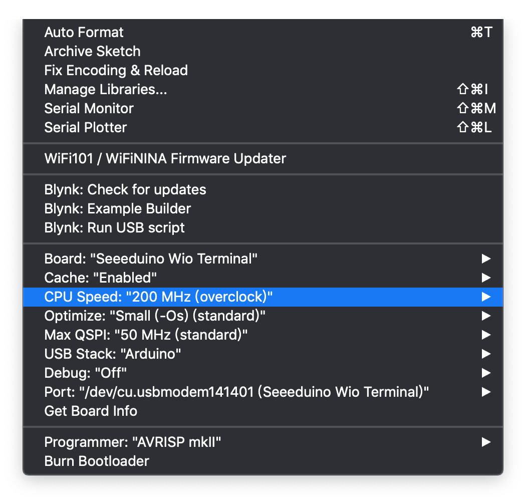
注意: 为了提升这个红外热成像相机的性能和帧率,您可以将 Wio Terminal CPU 速度提升到 200MHz。选择 Tools -> CPU Speed -> 200MHz(Overclock)
/*

  这个程序用于将8 x 8热像仪读数数组放大
  它将放大10倍并显示到240 x 320的屏幕上
  插值是线性的,考虑到显示器是5-6-5色彩调色板,这已经"足够好"了
  最终的总数组是一个70 x 70的内部点数组

  修订版本
  1.0     Kasprzak      初始代码
  1.1     Anson(Seeed Studio)  适配到Wio Terminal与Grove - 红外传感器(AMG8833)

*/

#include <Seeed_AMG8833_driver.h>
#include <TFT_eSPI.h>                // 包含图形库(这包括精灵函数)

TFT_eSPI    tft = TFT_eSPI();
TFT_eSprite Display = TFT_eSprite(&tft);  // 创建精灵对象"img",指向"tft"对象
// 指针被pushSprite()用来将其推送到TFT上

unsigned long CurTime;

uint16_t TheColor;
// 从一些初始颜色开始
uint16_t MinTemp = 25;
uint16_t MaxTemp = 35;

// 插值颜色的变量
byte red, green, blue;

// 行/列插值的变量
byte i, j, k, row, col, incr;
float intPoint, val, a, b, c, d, ii;
byte aLow, aHigh;

// 显示"像素"的大小
byte BoxWidth = 3;
byte BoxHeight = 3;

int x, y;
char buf[20];

// 切换显示网格的变量
int ShowGrid = -1;

// 8 x 8测量像素的数组
float pixels[64];

// 插值数组
float HDTemp[80][80];

// 创建摄像头对象
AMG8833 ThermalSensor;

//切换网格开关
void toggleGrid() {
  ShowGrid = ShowGrid *-1;
  Display.fillRect(15, 15, 210, 210, TFT_BLACK);
  yield();
}

void setup() {
  Serial.begin(115200);

  // 启动显示器并将背景设置为黑色
  tft.begin();
  tft.fillScreen(TFT_BLACK);

  //中断来切换网格开关
  pinMode(WIO_KEY_A, INPUT);
  attachInterrupt(digitalPinToInterrupt(WIO_KEY_A), toggleGrid, FALLING);

  // 设置显示旋转(根据你的显示器,你可能需要改为0
  tft.setRotation(3);

  // 显示启动画面

  tft.setCursor(20, 20);
  tft.setTextColor(TFT_BLUE, TFT_BLACK);
  tft.print("热像 ");

  tft.setTextColor(TFT_RED, TFT_BLACK);
  tft.print("摄像头");

  // 让传感器启动
  bool status = ThermalSensor.init();
  delay(100);

  if (!status) {
      Serial.print("初始化AMG8833失败");
  }

  // 读取摄像头进行初始测试
  ThermalSensor.read_pixel_temperature(pixels);

  // 检查状态并显示结果
  if (pixels[0] < 0) {
    while (1) {
      tft.setCursor(20, 40);
      tft.setTextColor(TFT_RED, TFT_BLACK);
      tft.print("读数: 失败");
      delay(500);
    }
  }
  else {
    tft.setCursor(20, 40);
    tft.setTextColor(TFT_GREEN, TFT_BLACK);
    tft.print("读数: 正常");
    delay(2000);
  }

  tft.fillScreen(TFT_BLACK);

  Display.createSprite(TFT_HEIGHT, TFT_WIDTH);
  Display.fillSprite(TFT_BLACK);

  // 获取颜色插值例程的截止点
  // 注意这个函数在温度刻度改变时被调用
  Getabcd();

  // 绘制与传感器最大值和最小值匹配的刻度图例
  DrawLegend();

}

void loop() {
  CurTime = millis();

  // 为温度区域绘制一个大的白色边框
  Display.fillRect(10, 10, 220, 220, TFT_WHITE);

  // 读取传感器
  ThermalSensor.read_pixel_temperature(pixels);

  // 现在我们有了一个8 x 8传感器数组
  // 插值以获得更大的屏幕
  // 插值8行(首先在8个传感器像素之间插值70个列点)
  for (row = 0; row < 8; row ++) {
    for (col = 0; col < 70; col ++) {
      // 获取第一个数组点,然后是下一个
      // 还需要为后续行增加8
      aLow =  col / 10 + (row * 8);
      aHigh = (col / 10) + 1 + (row * 8);
      // 获取每10列的插值量
      // 这里我们做简单的线性插值,主要是为了保持高性能
      // 显示器是5-6-5色彩调色板,所以精细插值会在低色彩深度中丢失
      intPoint =   (( pixels[aHigh] - pixels[aLow] ) / 10.0 );
      // 确定每列增加多少(基本上是0-9)
      incr = col % 10;
      // 找到插值
      val = (intPoint * incr ) +  pixels[aLow];
      // 存储在70 x 70数组中
      // 由于显示器指向远处,反转行以转置行数据
      HDTemp[ (7 - row) * 10][col] = val;

    }
  }

  // 现在我们有了70列的原始数据
  // 插值每个70列
  // 忘记Arduino..远远不够快..Teensy在> 72 mhz是起点

  for (col = 0; col < 70; col ++) {
    for (row = 0; row < 70; row ++) {
      // 获取第一个数组点,然后是下一个
      // 还需要为后续列增加8
      aLow =  (row / 10 ) * 10;
      aHigh = aLow + 10;
      // 获取每10列的插值量
      // 这里我们做简单的线性插值,主要是为了保持高性能
      // 显示器是5-6-5色彩调色板,所以精细插值会在低色彩深度中丢失
      intPoint =   (( HDTemp[aHigh][col] - HDTemp[aLow][col] ) / 10.0 );
      // 确定每列增加多少(基本上是0-9)
      incr = row % 10;
      // 找到插值
      val = (intPoint * incr ) +  HDTemp[aLow][col];
      // 存储在70 x 70数组中
      HDTemp[ row ][col] = val;
    }
  }


  //显示70 x 70数组
  DisplayGradient();

  //屏幕中央的十字准线
  Display.drawCircle(115, 115, 5, TFT_WHITE);
  Display.drawFastVLine(115, 105, 20, TFT_WHITE);
  Display.drawFastHLine(105, 115, 20, TFT_WHITE);

  //将精灵推送到屏幕
  Display.pushSprite(0, 0);

  //显示屏幕中央的温度
  tft.setRotation(3);
  tft.setTextColor(TFT_WHITE);
  tft.drawFloat(HDTemp[35][35], 2, 90, 20);

  //取消注释以打印帧率
  Serial.print("帧率: "); Serial.println(1/(0.001*(millis() - CurTime)));

}

// 显示结果的函数
void DisplayGradient() {

  tft.setRotation(4);

  // 遍历70行
  for (row = 0; row < 70; row ++) {

    // 绘制无闪烁网格的快速方法--只需将每10个像素设为2x2而不是3x3
    // 在网格后绘制线条会闪烁太多
    if (ShowGrid < 0) {
      BoxWidth = 3;
    }
    else {
      if ((row % 10 == 9) ) {
        BoxWidth = 2;
      }
      else {
        BoxWidth = 3;
      }
    }
    // 然后遍历每70列
    for (col = 0; col < 70; col++) {

      // 绘制无闪烁网格的快速方法--只需将每10个像素设为2x2而不是3x3
      if (ShowGrid < 0) {
        BoxHeight = 3;
      }
      else {
        if ( (col % 10 == 9)) {
          BoxHeight = 2;
        }
        else {
          BoxHeight = 3;
        }
      }
      // 最后我们可以绘制每个70 x 70点,注意调用获取插值颜色
      Display.fillRect((row * 3) + 15, (col * 3) + 15, BoxWidth, BoxHeight, GetColor(HDTemp[row][col]));
    }
  }

}

// 我的快速而有效的颜色插值例程
uint16_t GetColor(float val) {

  /*
    传入值并计算R G B
    有几种已发布的方法来做这件事,我基本上绘制了R G B图并开发了简单的线性方程
    再次,5-6-5颜色显示器不需要精确的温度到R G B颜色计算

    基于以下方程
    http://web-tech.ga-usa.com/2012/05/creating-a-custom-hot-to-cold-temperature-color-gradient-for-use-with-rrdtool/index.html

  */

  red = constrain(255.0 / (c - b) * val - ((b * 255.0) / (c - b)), 0, 255);

  if ((val > MinTemp) & (val < a)) {
    green = constrain(255.0 / (a - MinTemp) * val - (255.0 * MinTemp) / (a - MinTemp), 0, 255);
  }
  else if ((val >= a) & (val <= c)) {
    green = 255;
  }
  else if (val > c) {
    green = constrain(255.0 / (c - d) * val - (d * 255.0) / (c - d), 0, 255);
  }
  else if ((val > d) | (val < a)) {
    green = 0;
  }

  if (val <= b) {
    blue = constrain(255.0 / (a - b) * val - (255.0 * b) / (a - b), 0, 255);
  }
  else if ((val > b) & (val <= d)) {
    blue = 0;
  }
  else if (val > d) {
    blue = constrain(240.0 / (MaxTemp - d) * val - (d * 240.0) / (MaxTemp - d), 0, 240);
  }

  // 使用显示器的颜色映射函数获取5-6-5色彩调色板(R=5位,G=6位,B=5位)
  return Display.color565(red, green, blue);

}

// 获取温度与RGB图中截止点的函数
void Getabcd() {

  a = MinTemp + (MaxTemp - MinTemp) * 0.2121;
  b = MinTemp + (MaxTemp - MinTemp) * 0.3182;
  c = MinTemp + (MaxTemp - MinTemp) * 0.4242;
  d = MinTemp + (MaxTemp - MinTemp) * 0.8182;

}

// 绘制图例的函数
void DrawLegend() {

  //带有最大值和最小值文本的颜色图例
  j = 0;

  float inc = (MaxTemp - MinTemp ) / 160.0;

  for (ii = MinTemp; ii < MaxTemp; ii += inc) {
    tft.drawFastHLine(260, 200 - j++, 30, GetColor(ii));
  }

  tft.setTextSize(2);
  tft.setCursor(245, 20);
  tft.setTextColor(TFT_WHITE, TFT_BLACK);
  sprintf(buf, "%2d/%2d", MaxTemp, (int) (MaxTemp * 1.8) + 32);
  tft.print(buf);

  tft.setTextSize(2);
  tft.setCursor(245, 210);
  tft.setTextColor(TFT_WHITE, TFT_BLACK);
  sprintf(buf, "%2d/%2d", MinTemp, (int) (MinTemp * 1.8) + 32);
  tft.print(buf);

}

// 代码结束