Seeed Studio XIAO-RS485-扩展板入门指南
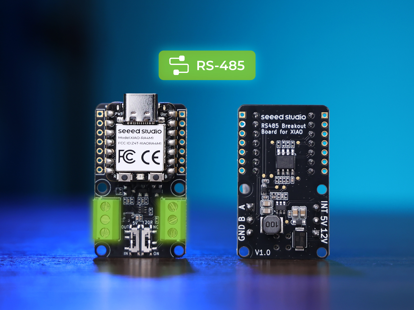
硬件概述
准备材料


引脚图
| XIAO RS485 扩展板指示图 |
|---|
 |
-
5V OUT/IN SWITCH:一个是 5V 端口的输入和输出,当从机设置为 IN 档时,作为输入,当主机设置为 OUT 档时,此端口向外放电,可以连接到传感器为传感器供电。
-
120R SWITCH:120R 开关用于确定 120 欧姆电阻是否可访问。485 需要在长布线环境的开始和结束处添加 120 欧姆电阻来进行匹配并确保通信。
-
INT:保留中断端口。
当用作输入模式时,需要将开关转到 IN,如果用作输出模式,需要将开关转到 OUT 以防止烧毁。
连接示意图
| 两个 RS485 扩展板连接 |
|---|
 |
在此项目中,XIAO ESP32C3 使用 D4 (GPIO6) 和 D5 (GPIO7) 与 RS485 扩展板通信。
如果使用不同的开发板,请根据需要修改相应的引脚配置。
软件概述
发送端代码
#include <HardwareSerial.h>

HardwareSerial mySerial(1);


#define enable_pin D2 // Define the enable pin as D2

void setup() {
  Serial.begin(115200); // Initialize the hardware serial with a baud rate of 115200
  mySerial.begin(115200, SERIAL_8N1, 7, 6); // RX=D4(GPIO6), TX=D5(GPIO7)


  // Wait for the hardware serial to be ready
  while(!mySerial);
  // Wait for the hardware serial to be ready
  while(!Serial);

  pinMode(enable_pin, OUTPUT); // Set the enable pin as an output
  digitalWrite(enable_pin, HIGH); // Set the enable pin to high
}

void loop() {
if (Serial.available()) {
    String receivedData = Serial.readStringUntil('\n'); // Read the data from the hardware serial until a newline character

    // If the received data is not empty
    if (receivedData.length() > 0) {
        Serial.println("Send successfully"); // Print a success message
        mySerial.print("Master send information is: "); // Send a prompt message to the hardware serial
        mySerial.println(receivedData); // Send the received data to the hardware serial
    }
  }
}
-
HardwareSerial 库: 允许在 ESP32 上创建额外的串行端口,通常用于与设备(如传感器或模块)通信。
-
HardwareSerial mySerial(1);:定义一个名为 mySerial 的 HardwareSerial 对象,使用 D5 和 D4 作为接收和发送引脚。 -
#define enable_pin D2:定义一个使能引脚,用于控制 RS485 模块的发送和接收状态。 -
setup():Serial.begin(115200:以 115200 的波特率初始化硬件串口。mySerial.begin(115200, SERIAL_8N1, 7, 6);:RX=D4(GPIO4),TX=D5(GPIO5)。while(!mySerial):等待直到硬件串口准备好进行通信。while(!Serial):等待直到硬件串口准备好进行通信。pinMode(enable_pin, OUTPUT):将 enable_pin 配置为输出引脚以控制 RS485 模块。digitalWrite(enable_pin, HIGH):将 enable_pin 设置为 HIGH,配置 RS485 模块为发送模式。
-
loop():if (receivedData.length() > 0):检查硬件串口是否有可读取的数据。String receivedData = Serial.readStringUntil('\n');:从硬件串口读取数据直到换行符Serial.println("Send successfully"):打印成功消息。mySerial.print("Master send information is: "):向硬件串口发送提示消息。mySerial.println(receivedData):将您需要的数据发送到 RS485 扩展板。
接收端代码
#include <HardwareSerial.h>

HardwareSerial mySerial(1); // Use UART2
#define enable_pin D2 // Define the enable pin as D2

void setup() {
  Serial.begin(115200); // Initialize the hardware serial with a baud rate of 115200
  mySerial.begin(115200, SERIAL_8N1, 7, 6); // RX=D4(GPIO4), TX=D5(GPIO5)

  // Wait for the hardware serial to be ready
  while(!Serial);
  // Wait for the hardware serial to be ready
  while(!mySerial);

  pinMode(enable_pin, OUTPUT); // Set the enable pin as an output
  digitalWrite(enable_pin, LOW); // Set the enable pin to low
}

void loop() {
  // Check if there is data available from the hardware serial
  if (mySerial.available()) {
      String receivedData = mySerial.readStringUntil('\n'); // Read strings based on newlines
      Serial.print("Received data: ");
      Serial.println(receivedData); // Direct printing of received data
  }
}
-
HardwareSerial 库: 允许在 ESP32 上创建额外的串行端口,通常用于与设备(如传感器或模块)通信。
-
HardwareSerial mySerial(1);:定义一个名为 mySerial 的 HardwareSerial 对象,使用 D5 作为 RX,D4 作为 TX。 -
define enable_pin D2:定义一个使能引脚,用于控制 RS485 模块的发送和接收状态。 -
setup():Serial.begin(115200:以 115200 的波特率初始化硬件串口。mySerial.begin(115200, SERIAL_8N1, 7, 6);RX=D4(GPIO4),TX=D5(GPIO5)。while(!Serial):等待直到硬件串口准备好进行通信。while(!mySerial):等待直到硬件串口准备好进行通信。pinMode(enable_pin, OUTPUT):将 enable_pin 配置为输出引脚以控制 RS485 模块。digitalWrite(enable_pin, LOW):将 enable_pin 设置为低电平,配置 RS485 模块为接收模式。
-
loop():if (mySerial.available()):检查硬件串口是否有可读取的数据。String receivedData = mySerial.readStringUntil('\n');:基于换行符读取字符串Serial.print("Received data: ");:向硬件串口打印消息,指示已接收到数据。Serial.println(receivedData);:打印发送到接收端 RS485 的数据。
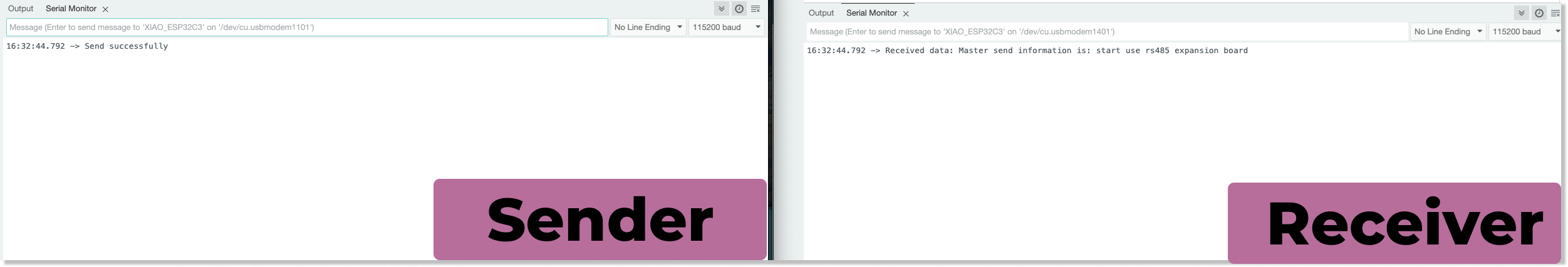
RS485 传输结果
资源
技术支持与产品讨论
感谢您选择我们的产品!我们在这里为您提供不同的支持,以确保您使用我们产品的体验尽可能顺畅。我们提供多种沟通渠道,以满足不同的偏好和需求。