Seeed Studio XIAO SAMD21 与 MicroPython
MicroPython 简介
MicroPython 是一个带有部分原生代码编译功能的 Python 解释器。它为嵌入式处理器和受限系统实现了 Python 3.5 功能的一个子集。它与 CPython 不同,你可以在这里阅读更多差异说明。

入门指南
首先,我们将 Seeed Studio XIAO SAMD21 连接到电脑,并从 MicroPython 上传一段简单代码,以检查开发板是否工作正常。
硬件准备
- Seeed Studio XIAO SAMD21 或 Seeed Studio XIAO SAMD21 Plus x1
- Type-C 线 x1
- 电脑 x1
烧录固件
适用于 XIAO SAMD21
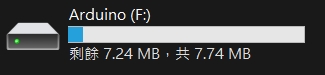
- 步骤 1. 通过 Type‑C 线将 Seeed Studio XIAO SAMD21 连接到电脑,然后双击 Reset 按钮进入 BOOT 模式。如果一切正常,电脑上会出现一个名为 Arduino 的磁盘。
- 步骤 2. 烧录固件
只需前往 MicroPython 官方网站并下载最新固件
你也可以编译你自己的固件,以确保安全性并支持最新特性,但这不是必须的。
适用于 XIAO SAMD21 Plus
- 步骤 1. 使用 Type‑C 线将 XIAO SAMD21 Plus 连接到电脑,然后连续按下 Reset 按钮两次。如果一切正常,电脑上会出现一个 Arduino 磁盘。
-
步骤 2. 点击下方链接下载固件,然后将
.uf2文件拖放到 Arduino 磁盘中完成固件烧录。
软件准备
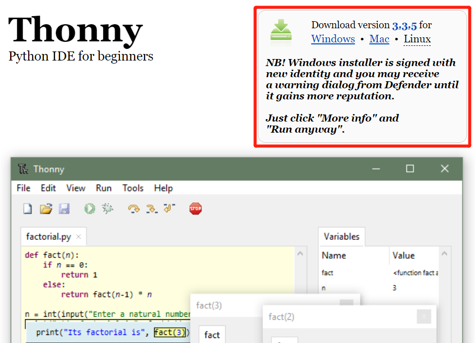
- 步骤 1. 根据你的操作系统下载并安装最新版本的 Thonny editor
-
步骤 2. 启动 Thonny
-
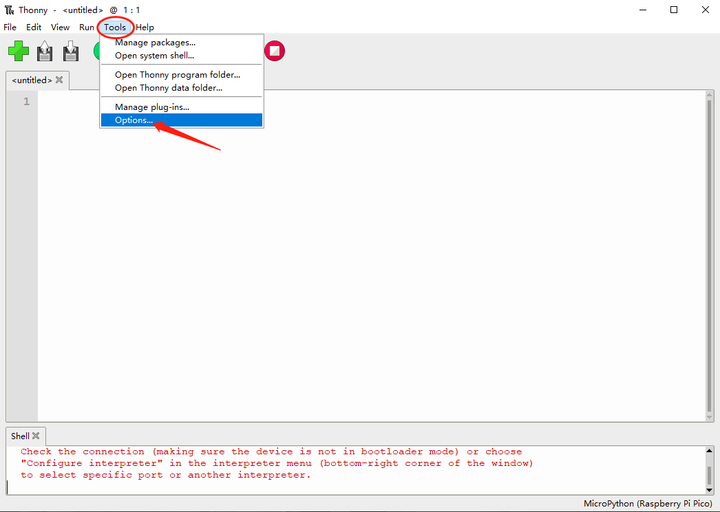
步骤 3. 点击 Tools-->Options 打开设置。
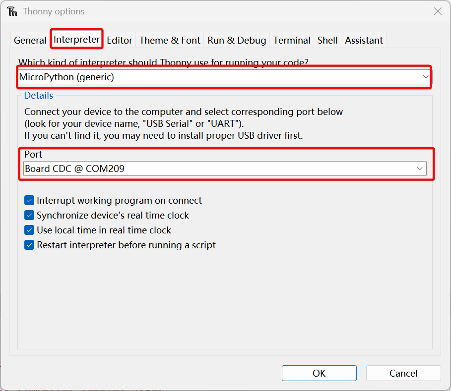
- 步骤 4. 选择 Interpreter 选项卡,将设备选择为 MicroPython(generic),端口选择为 Board CDC @ Port
软件开发
SEEED XIAO SAMD21 系列引脚分配表
| MicroPython 引脚名 | XIAO SAMD21 GPIO (ID) | XIAO SAMD21 Plus GPIO (ID) | IRQ SAMD21 / Plus | ADC | 功能 |
|---|---|---|---|---|---|
| D0 / A0 | PA02 (2) | PA02 (2) | 2 / 2 | 0 | GPIO, ADC, DAC |
| D1 / A1 | PA04 (4) | PA04 (4) | 4 / 4 | 4 | GPIO, ADC |
| D2 / A2 | PA10 (10) | PA10 (10) | 10 / 10 | 18 | GPIO, ADC |
| D3 / A3 | PA11 (11) | PA11 (11) | 11 / 11 | 19 | GPIO, ADC |
| D4 / A4 / SDA | PA08 (8) | PA08 (8) | NMI / NMI | 16 | GPIO, ADC, I2C SDA |
| D5 / A5 / SCL | PA09 (9) | PA09 (9) | 9 / 9 | 17 | GPIO, ADC, I2C SCL |
| D6 / A6 / TX | PB08 (40) | PB08 (40) | 8 / 8 | 2 | GPIO, ADC, UART TX |
| D7 / A7 / RX | PB09 (41) | PB09 (41) | 9 / 9 | 3 | GPIO, ADC, UART RX |
| D8 / A8 / SCK | PA07 (7) | PA07 (7) | 7 / 7 | 7 | GPIO, ADC, SPI SCK |
| D9 / A9 / MISO | PA05 (5) | PA05 (5) | 5 / 5 | 5 | GPIO, ADC, SPI MISO |
| D10 / A10 / MOSI | PA06 (6) | PA06 (6) | 6 / 6 | 6 | GPIO, ADC, SPI MOSI |
| USER_LED / D13 / SCL1 | PA17 (17) | PA17 (17) | 1 / 1 | — | 原始用户 LED;Plus D13 和 I2C1 SCL |
| RX_LED / D27 | PA18 (18) | PA18 (18) | 2 / 2 | — | 原始 RX LED;Plus D27 |
| TX_LED / D19 / I2S_SD | PA19 (19) | PA19 (19) | 3 / 3 | — | 原始 TX LED;Plus D19 和 I2S 数据 |
| D12 | — | PA28 (28) | — / 8 | — | Plus 扩展 GPIO |
| D14 / SDA1 | — | PA16 (16) | — / 0 | — | Plus I2C1 SDA |
| D15 | — | PA15 (15) | — / 15 | — | Plus 扩展 GPIO |
| D16 | — | PA14 (14) | — / 14 | — | Plus 扩展 GPIO |
| D17 | — | PA13 (13) | — / 13 | — | Plus 扩展 GPIO |
| D18 | — | PA12 (12) | — / 12 | — | Plus 扩展 GPIO |
| D20 / I2S_SCK | — | PA20 (20) | — / 4 | — | Plus GPIO 和 I2S 时钟 |
| D21 / I2S_WS | — | PA21 (21) | — / 5 | — | Plus GPIO 和 I2S 字选择 |
| D22 | — | PB10 (42) | — / 10 | — | Plus 扩展 GPIO |
| D23 | — | PB11 (43) | — / 11 | — | Plus 扩展 GPIO |
| D24 | — | PB23 (55) | — / 7 | — | Plus 扩展 GPIO |
| D25 | — | PA23 (23) | — / 7 | — | Plus 扩展 GPIO |
| D26 | — | PA22 (22) | — / 6 | — | Plus 扩展 GPIO |
| RGB_LED | — | PA27 (27) | — / 15 | — | Plus 可寻址 RGB LED (WS2812) |
| BUTTON | — | PB22 (54) | — / 6 | — | Plus 用户按键(低电平有效) |
| USB_DM | PA24 (24) | PA24 (24) | 12 / 12 | — | USB D−(原生 USB,非 GPIO) |
| USB_DP | PA25 (25) | PA25 (25) | 13 / 13 | — | USB D+(原生 USB,非 GPIO) |
| SWCLK | PA30 (30) | PA30 (30) | 10 / 10 | — | SWD 时钟 |
| SWDIO | PA31 (31) | PA31 (31) | 11 / 11 | — | SWD 数据 |
GPIO (ID) 中括号内的数字指的是 MicroPython SAMD 引脚 ID,而不是 MCU 封装的物理引脚编号。
上传你的代码
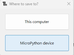
点击 "Run current script" 按钮上传代码。第一次运行时,Thonny 会询问你要将代码文件保存到哪里。选择 This Computer 或 MicroPython device 都可以。
如果你想离线运行程序,应将程序保存到 XIAO SAMD21 上。
同时按住 Ctrl + Shift + S,然后选择保存到 MicroPython device
GPIO 测试(LED)
我们需要准备:
-
将以下代码复制到 Thonny 中。
-
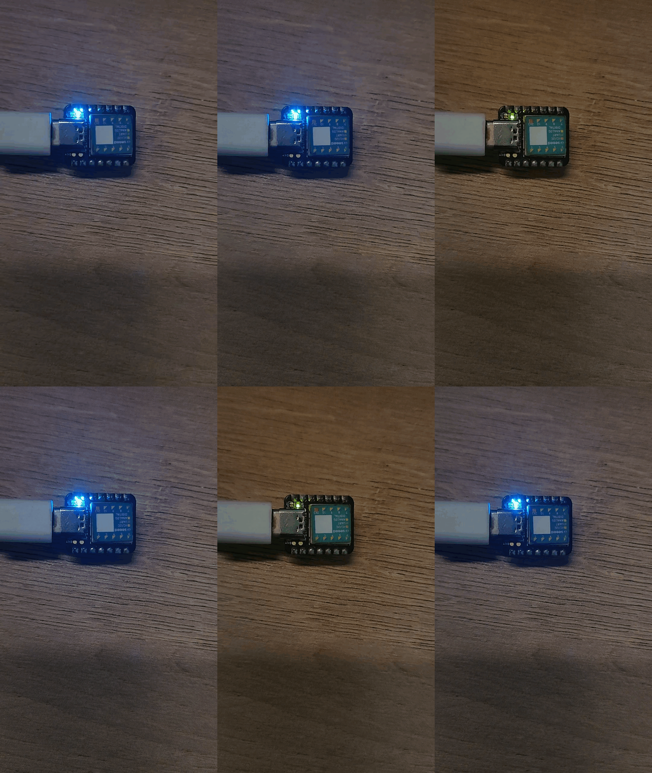
对于 XIAO SAMD21,RX_LED 为 PA18
我们可以看到蓝色的 RX_LED 被点亮,并以每秒一次的频率闪烁
from machine import Pin, Timer

led = Pin(18, Pin.OUT)
Counter = 0
Fun_Num = 0

def fun(tim):
    global Counter
    Counter = Counter + 1
    print(Counter)
    led.value(Counter%2)

tim = Timer(-1)
tim.init(period=500, mode=Timer.PERIODIC, callback=fun)
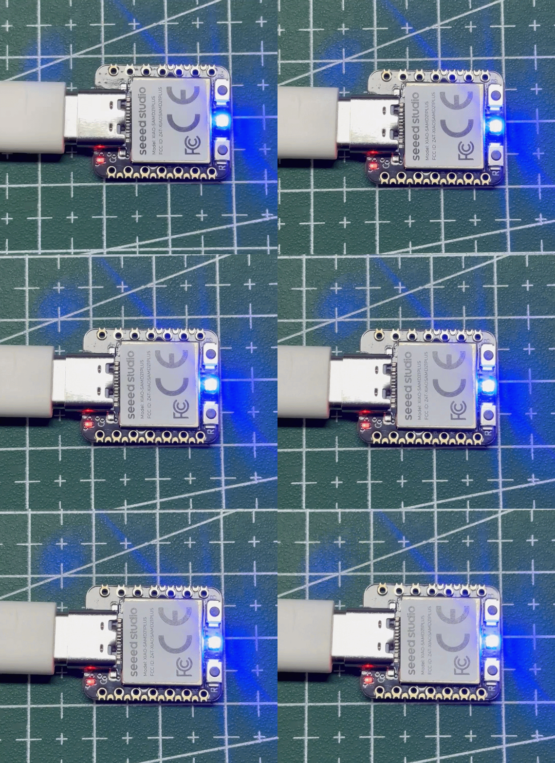
- 对于 XIAO SAMD21 Plus,RX_LED 和 TX_LED 已被移除。改用一个 WS2812 LED,其数据引脚连接到 PA27。
from machine import Pin, Timer
import machine
import time

led = Pin(27, Pin.OUT)

Counter = 0


def ws2812_write(r, g, b):
    data = bytearray([g, r, b])

    machine.bitstream(
        led,
        0,
        (400, 850, 800, 450),
        data
    )

    time.sleep_us(80)


def fun(tim):
    global Counter

    Counter += 1
    print(Counter)

    if Counter % 2 == 1:
        ws2812_write(0, 0, 255)
    else:
        ws2812_write(0, 0, 0)


# Initial state: OFF
ws2812_write(0, 0, 0)

# 500 ms periodic timer
tim = Timer(-1)
tim.init(
    period=500,
    mode=Timer.PERIODIC,
    callback=fun
)
GPIO 控制继电器
我们需要准备:
from machine import Pin, Timer

output_4 = Pin(8, Pin.OUT)
detect_1 = Pin(4, Pin.IN, Pin.PULL_UP)
output_value = Pin(2, Pin.OUT)
Counter = 0

def fun(tim):
    global Counter
    Counter = Counter + 1
    output_4.value(Counter%2)
    print(Counter%2,detect_1.value())
    if detect_1.value() :
        output_value.value(1)
    else:
        output_value.value(0)

tim = Timer(-1)
tim.init(period=200, mode=Timer.PERIODIC, callback=fun)
自动控制的人体检测
我们需要准备:
from machine import Pin, Timer

led = Pin(8, Pin.OUT)

input_value_1 = Pin(4, Pin.IN, Pin.PULL_UP)
input_value_2 = Pin(10, Pin.IN, Pin.PULL_UP)
output_value = Pin(2, Pin.OUT)

Counter = 0
Fun_Num = 0

def fun(tim):
    global Counter
    Counter = Counter + 1
    led.value(Counter%2)
    print(input_value_1.value(),input_value_2.value())
    if input_value_1.value() :
        output_value.value(1)
    else:
        output_value.value(0)

tim = Timer(-1)
tim.init(period=50, mode=Timer.PERIODIC, callback=fun)
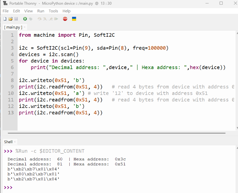
I2C 支持
from machine import Pin, SoftI2C

i2c = SoftI2C(scl=Pin(9), sda=Pin(8), freq=100000)
devices = i2c.scan()
for device in devices:
    print("Decimal address: ",device," | Hexa address: ",hex(device))

i2c.writeto(0x51, 'b')
print(i2c.readfrom(0x51, 4))   # read 4 bytes from device with address 0x51
i2c.writeto(0x51, 'a') # write 'a' to device with address 0x51
print(i2c.readfrom(0x51, 4))   # read 4 bytes from device with address 0x51
i2c.writeto(0x51, 'b')
print(i2c.readfrom(0x51, 4))
熟悉 micropython 能让你做到更多,我们期待为你创造更多价值。也欢迎随时与我们分享你的项目!
DAC 支持
感谢 Aleksei Tertychnyi 提交代码,所有相关功能均由他开发并贡献。
from machine import Pin, Timer, DAC

led = Pin(18, Pin.OUT)
counter = 0

dac = DAC(0) #DAC on A0 output

def loop(tim):
    global counter
    led.value(counter%2)
    print('DAC value: ', end =" ")
    print(counter)
    dac.write(counter%1024)
    counter = counter + 1

tim = Timer(-1)
tim.init(period=1000, mode=Timer.PERIODIC, callback=loop)
A0 引脚上的电压将开始逐渐升高,在大约 3.3V 达到最大值后,会降至 0V,然后循环重复。
ADC 支持
ADC 示例 MicroPython 代码:
from machine import Pin, Timer, ADC
led = Pin(18, Pin.OUT)  # digital output for blinking
counter = 0             # simple counter for LED toggle

ADC_CONVERT_V = 1.0 / 65535.0  # conversion factor: raw ADC (16-bit) → voltage (vref=1.0V)

adc = ADC(4, vref=0)   # ADC reads on pin A4, using internal 1.0V reference
adcVoltage = 0.0       # variable to store measured voltage

def fun(tim):
    global counter, adcVoltage  # make sure we update the global variables
    counter += 1                # increment counter
    adcVoltage = adc.read_u16() * ADC_CONVERT_V  # read ADC and convert to voltage
    print(adcVoltage)           # print voltage to REPL
    led.value(counter % 2)      # toggle LED every callback (blink)

tim = Timer(-1)                    # create a virtual timer
tim.init(period=1000,              # callback period in milliseconds (1000 ms = 1 s)
         mode=Timer.PERIODIC,      # periodic callback
         callback=fun)             # function to call
MicroPython 设备控制台
我们的合作伙伴 Neil 使用 MicroPython 为 XIAO 编写了一个命令行控制台程序。通过这个程序,你可以轻松上传、下载和删除文件。我们感谢他对 XIAO 的贡献!
技术支持与产品讨论
感谢你选择我们的产品!我们将为你提供多种支持,以确保你在使用我们产品时拥有尽可能顺畅的体验。我们提供多种沟通渠道,以满足不同的偏好和需求。