总线舵机驱动板 / XIAO总线舵机适配器入门指南
本wiki涵盖两个相关产品:总线舵机驱动板和XIAO总线舵机适配器。
-
总线舵机驱动板不包含板载XIAO ESP32-C3微控制器,也不配备3D打印外壳。它被设计为通用总线舵机接口板,允许您通过您选择的外部控制器连接和控制舵机。
-
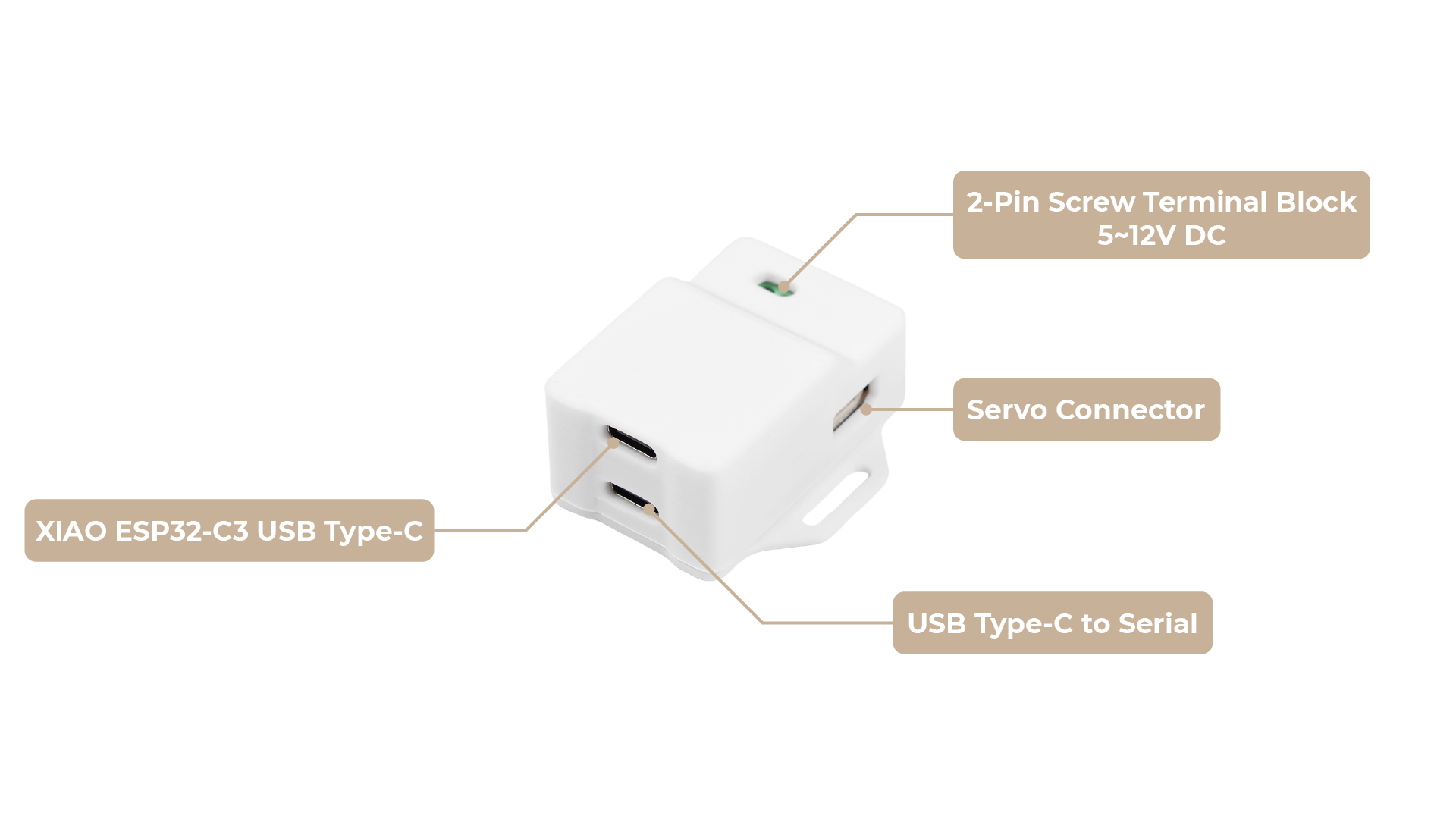
另一方面,XIAO总线舵机适配器包含XIAO ESP32-C3作为主控制器,并配有3D打印外壳。使用此版本,您可以直接使用板载XIAO控制总线舵机,使其成为机器人项目更集成和即用的解决方案。
请参考本指南的其余部分了解两种产品的设置和使用详情。


介绍
总线舵机驱动板 / XIAO 总线舵机适配器是来自矽递科技的紧凑而强大的硬件解决方案,专为机器人和自动化项目中驱动串行总线舵机而设计。通过支持 UART 通信,它能够实现对多个 ST/SC 系列舵机的精确控制和反馈,包括飞特 SCS 系列(参见飞特 SCS/STS/TTL 系列官方网站)。这使其非常适合需要舵机角度和负载反馈的应用,如机械臂、六足机器人、人形机器人和轮式机器人。
本指南重点介绍硬件设置、物理连接、关键规格和重要的跳线设置,以帮助用户有效地将该板集成到他们的项目中。
在连接或断开舵机或接线之前,请务必断开电源。确保输入电压与舵机要求匹配,以避免损坏。
硬件概述
- 总线舵机驱动板
- XIAO 总线舵机适配器
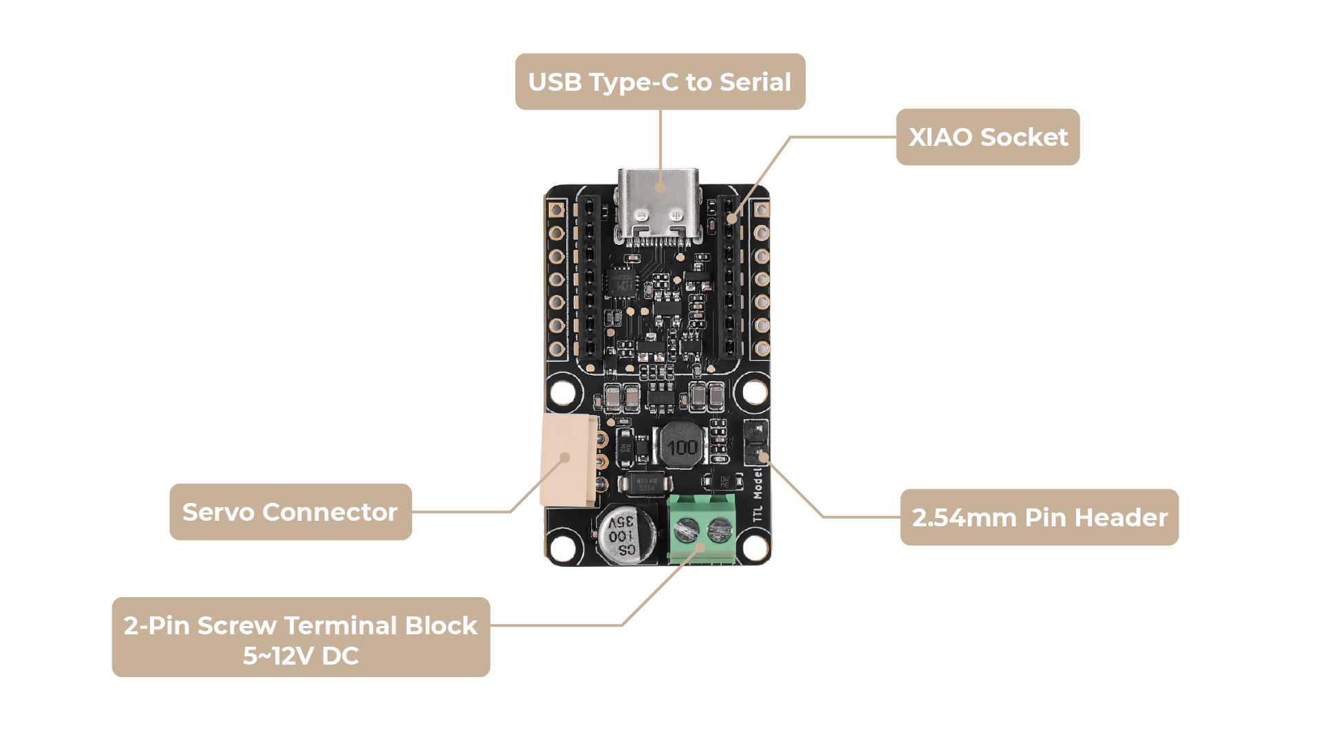
总线舵机驱动板具有几个关键连接点:
输入:
- DC IN (5.5 * 2.1mm): 这是板子和连接舵机的电源输入。在此连接 5~12V 电源。关键是,此电源的电压必须与您的舵机的电压要求匹配。 例如,ST 系列舵机通常在 9V 下工作,而 SC 系列舵机可能需要 12V。
输出:
- 舵机接口: 这是连接 ST/SC 系列总线舵机的专用端口。确保连接器正确对齐。
控制接口:
- UART (RX/TX): 这些引脚提供用于控制舵机的串行通信。连接方法和跳线设置取决于您的主机设备。详情请参见下文。
输入:
- DC IN (5.5 * 2.1mm): 这是板子和连接舵机的电源输入。在此连接 5~12V 电源。关键是,此电源的电压必须与您的舵机的电压要求匹配。 例如,ST 系列舵机通常在 9V 下工作,而 SC 系列舵机可能需要 12V。
输出:
- 舵机接口: 这是连接 ST/SC 系列总线舵机的专用端口。确保连接器正确对齐。
入门指南
选择驱动板的工作模式 (仅适用于总线舵机驱动板)
对于 XIAO 总线舵机适配器,您无需修改任何电路即可使用内置的 XIAO ESP32-C3 来控制舵机,您可以直接跳过这部分。
总线舵机驱动板提供两种主要连接方法:直接 UART 连接和通过 USB 转 UART 适配器的 USB 连接。正确的跳线设置对于正常工作至关重要。
UART 连接(适用于 MCU、XIAO、ESP32 等)
当直接连接到微控制器(MCU)的 UART 引脚时使用此方法,如 ESP32、Arduino、Seeed Studio XIAO 或单板计算机。
-
接线:
- 将驱动板上的
RX引脚连接到主机设备的TX引脚(D7)。 - 将驱动板上的
TX引脚连接到主机设备的RX引脚(D6)。 - 对于 Seeed Studio XIAO 等设备,您可以直接将 XIAO 插入提供的排针,确保引脚对齐正确。这样就无需为 UART 连接使用单独的杜邦线。
- 将驱动板上的
-
跳线设置(关键):
- 无需使用 2.54mm 跳线帽短接板子正面的 2pin 引脚。(默认未短接)

- 无需使用 2.54mm 跳线帽短接板子正面的 2pin 引脚。(默认未短接)
-
为主机供电: 您的主机设备(如 Raspberry Pi Zero、ESP32、XIAO)需要自己的独立电源。
USB 连接
当连接到带有 USB 端口的计算机或单板计算机时使用此方法(如 PC 或 Raspberry Pi 4B)。您只需使用 USB 线将控制板连接到计算机。
-
接线:
- 只需使用 USB 线将控制板连接到您的计算机。
-
跳线设置(关键):
-
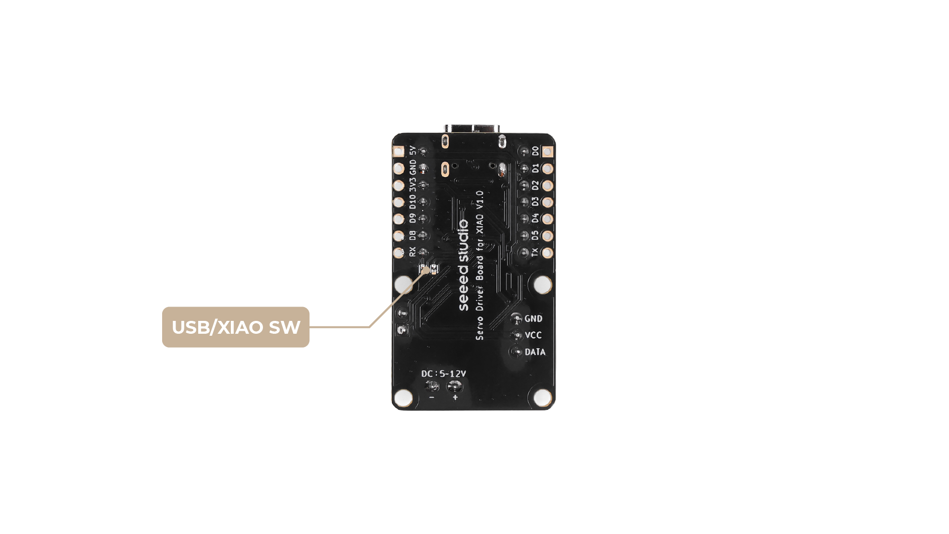
步骤 1. 找到板子背面的焊接跳线。对于 USB 通信,您必须确保两个焊盘已连接(它们之间有焊桥)。
-
版本 1 的背面焊盘:

-
版本 2 的背面焊盘:

-
步骤 2. 使用 2.54mm 跳线帽短接板子正面的 2pin 引脚。(默认未短接)
-
所需组件(开始之前)
在连接任何东西之前,请确保您有以下物品:
- 总线舵机驱动板 / XIAO 总线舵机适配器
- 兼容的 ST/SC 系列总线舵机:请参阅 飞特 SCS/STS/TTL 系列官方网站。
- 5~12V 电源: 电池或电源适配器。电压必须与您的舵机规格匹配。
- 主机设备:
- 对于直接 UART: 支持 UART 的设备,如 Raspberry Pi、Arduino、ESP32 或 Seeed Studio XIAO。
- 对于 USB: 计算机(PC、Mac、Linux)或单板计算机如 Raspberry Pi 4B,加上 USB 转 UART 适配器。
对于 XIAO 总线舵机适配器,内置了 XIAO ESP32-C3,因此无需准备主机设备。
- 连接线/适配器: 如果使用直接 UART,需要跳线(杜邦线)(除非使用 XIAO 直接排针连接)。如果使用 USB 连接方法,需要 USB 转 UART 适配器。
如果使用 SC 系列舵机,请确认电源符合其电压要求。板子的 DC 输入标签是为 ST 系列舵机定制的,但也支持 SC 系列电压。错误的跳线设置将阻止与驱动板的通信。
通过 USB 控制舵机
本节介绍如何通过 USB 连接使用总线舵机驱动板控制多个总线舵机。
原理概述
总线舵机驱动板的工作原理是通过 USB 接收来自主机设备(如 PC、树莓派或微控制器)的串行(UART)命令。这些命令随后被转发到连接的总线舵机。通过发送适当的串行协议命令,您可以单独控制每个舵机的位置、速度和其他参数。
驱动板本身不会自主解释或生成舵机控制信号;相反,它充当主机和舵机之间的透明桥梁。这意味着您需要负责根据舵机的通信协议发送正确的命令数据包。
示例参考
有关如何向 Feetech(ST/SC/STS/TTL 系列)总线舵机发送命令的实际示例,您可以参考以下 Python 示例:
GitHub 上的 lerobot/common/robot_devices/motors/feetech.py
此示例演示了如何构造和发送串行数据包来控制 Feetech 舵机。您可以根据需要将代码适配到您自己的主机平台和编程语言。
注意:
- 具体的命令格式和协议可能因您的舵机型号而异。
- 请查阅您舵机的官方文档以获取正确的串行协议和命令结构。
- 您需要编写或适配一个符合您舵机要求的驱动程序。
有关 Feetech SCS/STS/TTL 系列协议的更多详细信息,请参阅 Feetech 官方文档。
通过 XIAO 控制舵机
接下来,我们介绍如何通过 XIAO 发送信号来控制舵机运动以及如何使用库。
Arduino 库概述
如果这是您第一次使用 Arduino,我们强烈建议您参考 Arduino 入门指南。
功能
在我们开始开发代码之前,让我们先了解一下库的可用功能。
-
SMS_STS(uint8_t id)—— 创建具有指定 ID 的舵机对象。
参数:uint8_t id(舵机 ID)
输出:无 -
void WritePos(uint8_t id, int16_t Position, uint16_t Time, uint16_t Speed)—— 设置舵机的目标位置、时间和速度。
参数:uint8_t id、int16_t Position、uint16_t Time、uint16_t Speed
输出:无 -
void RegWritePos(uint8_t id, int16_t Position, uint16_t Time, uint16_t Speed)—— 设置舵机的目标位置、时间和速度,但稍后使用 Action 命令执行。
参数:uint8_t id、int16_t Position、uint16_t Time、uint16_t Speed
输出:无 -
void RegWriteAction()—— 执行所有已注册的 RegWritePos 命令。
参数:无
输出:无 -
void WriteSpe(uint8_t id, int16_t Speed)—— 设置舵机的旋转速度。
参数:uint8_t id、int16_t Speed
输出:无 -
void WritePosEx(uint8_t id, int16_t Position, uint16_t Time, uint16_t Speed, uint8_t ACC)—— 设置位置、时间、速度和加速度。
参数:uint8_t id、int16_t Position、uint16_t Time、uint16_t Speed、uint8_t ACC
输出:无 -
void RegWritePosEx(uint8_t id, int16_t Position, uint16_t Time, uint16_t Speed, uint8_t ACC)—— 注册位置、时间、速度和加速度,稍后执行。
参数:uint8_t id、int16_t Position、uint16_t Time、uint16_t Speed、uint8_t ACC
输出:无 -
void RegWriteActionEx()—— 执行所有已注册的 RegWritePosEx 命令。
参数:无
输出:无 -
int16_t ReadPos(uint8_t id)—— 读取舵机的当前位置。
参数:uint8_t id
输出:int16_t(位置) -
int16_t ReadSpeed(uint8_t id)—— 读取舵机的当前速度。
参数:uint8_t id
输出:int16_t(速度) -
int16_t ReadLoad(uint8_t id)—— 读取舵机的当前负载。
参数:uint8_t id
输出:int16_t(负载) -
int16_t ReadVoltage(uint8_t id)—— 读取舵机的当前电压。
参数:uint8_t id
输出:int16_t(电压) -
int16_t ReadTemper(uint8_t id)—— 读取舵机的当前温度。
参数:uint8_t id
输出:int16_t(温度) -
int16_t ReadMove(uint8_t id)—— 检查舵机是否正在运动。
参数:uint8_t id
输出:int16_t(1:运动中,0:已停止) -
int16_t ReadCurrent(uint8_t id)—— 读取舵机的电流。
参数:uint8_t id
输出:int16_t(电流) -
void SetID(uint8_t id, uint8_t newid)—— 为舵机设置新的 ID。
参数:uint8_t id、uint8_t newid
输出:无 -
void Load(uint8_t id)—— 启用舵机扭矩。
参数:uint8_t id
输出:无 -
void Unload(uint8_t id)—— 禁用舵机扭矩。
参数:uint8_t id
输出:无 -
int16_t ReadTorque(uint8_t id)—— 读取舵机的扭矩状态。
参数:uint8_t id
输出:int16_t(1:已启用,0:已禁用) -
void LEDAlarm(uint8_t id, uint8_t enable)—— 设置LED报警状态。
参数:uint8_t id,uint8_t enable
输出:无 -
void Reset(uint8_t id)—— 将舵机重置为出厂设置。
参数:uint8_t id
输出:无 -
void LockEprom(uint8_t id)—— 锁定舵机的EEPROM。
参数:uint8_t id
输出:无 -
void UnlockEprom(uint8_t id)—— 解锁舵机的EEPROM。
参数:uint8_t id
输出:无
XIAO示例
现在我们已经安装了库并了解了基本功能,让我们为我们的产品名称运行一些示例,看看它的表现如何。
步骤1. 启动Arduino应用程序。
步骤2. 选择您的开发板型号并将其添加到Arduino IDE中。
- 要在后续例程中使用Seeed Studio XIAO ESP32-C3,请参考**此教程**完成添加。
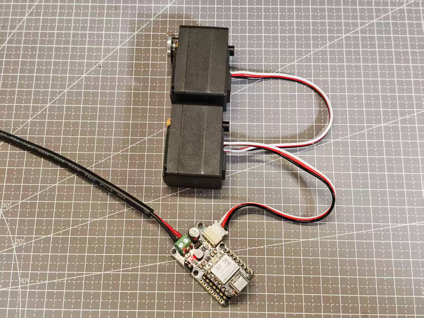
步骤3. 按照图示完成接线。如果您需要连接多个舵机,可以使用舵机附带的线缆完成连接。
控制多个舵机
#include <SCServo.h>

// Define the correct serial port for your target board
#if defined(CONFIG_IDF_TARGET_ESP32C3) || defined(CONFIG_IDF_TARGET_ESP32C6) || defined(CONFIG_IDF_TARGET_ESP32S3)
#define COMSerial Serial0
#else
#define COMSerial Serial1
#endif

// Define RX/TX pins for the servo bus (for reference)
// Note: On ESP32, pins are usually specified in COMSerial.begin().
// For example: COMSerial.begin(1000000, SERIAL_8N1, S_RXD, S_TXD);
// If your board uses the default pins for Serial1, no extra specification is needed.
#define S_RXD D7
#define S_TXD D6

#define SERVO_NUM 2 // Number of servos

SMS_STS st; // Servo control object

// --- Servo Configuration ---
byte ID[SERVO_NUM] = {1, 2};                // IDs of the servos
u16 Speed[SERVO_NUM] = {1500, 1500};         // Set a medium speed for the servos
byte ACC[SERVO_NUM] = {50, 50};             // Set a medium acceleration for the servos
s16 Pos[SERVO_NUM] = {2048, 2048};           // Servo position array, initialized to the midpoint (2048)

void setup()
{
  // Start the main serial port for debugging and receiving commands
  Serial.begin(115200);
  // Wait a moment for the Serial Monitor to connect
  delay(2000);
  Serial.println("--- Servo Control Program Start ---");

  // Start the serial port for controlling the servos
  COMSerial.begin(1000000, SERIAL_8N1);
  st.pSerial = &COMSerial; // Associate the control object with the serial port

  Serial.println("Checking servo connection status...");
  for (int i = 0; i < SERVO_NUM; i++) {
    if (st.Ping(ID[i]) != -1) {
      Serial.print("Servo with ID ");
      Serial.print(ID[i]);
      Serial.println(" is connected.");
    } else {
      Serial.print("Error: Servo with ID ");
      Serial.print(ID[i]);
      Serial.println(" is not responding!");
    }
  }

  // --- Power-on Self-Test ---
  // This section makes the servos move automatically on power-up to confirm they are working correctly.
  Serial.println("\nExecuting power-on self-test movement...");

  // 1. Move to position 1024
  Serial.println("Moving to position 1024...");
  for(int i=0; i<SERVO_NUM; i++) {
    Pos[i] = 1024;
  }
  st.SyncWritePosEx(ID, SERVO_NUM, Pos, Speed, ACC);
  delay(2000); // Wait for the movement to complete

  // 2. Move to position 3072
  Serial.println("Moving to position 3072...");
  for(int i=0; i<SERVO_NUM; i++) {
    Pos[i] = 3072;
  }
  st.SyncWritePosEx(ID, SERVO_NUM, Pos, Speed, ACC);
  delay(2000); // Wait for the movement to complete

  // 3. Return to center position (2048) to prepare for user commands
  Serial.println("Returning to center position (2048)...");
  for(int i=0; i<SERVO_NUM; i++) {
    Pos[i] = 2048;
  }
  st.SyncWritePosEx(ID, SERVO_NUM, Pos, Speed, ACC);
  delay(1500);

  Serial.println("\n--- Initialization Complete ---");
  Serial.println("Enter 'j' to decrease the angle, or 'k' to increase it.");
  Serial.println("-----------------------------------");
}

void loop()
{
  // Check if the user has sent a command via the Serial Monitor
  if (Serial.available()) {
    String input = Serial.readString();
    input.trim(); // Remove extra spaces or newlines

    bool shouldMove = false; // Flag to indicate if a valid command was received

    if (input.startsWith("j")) {
      Serial.println("Received command: 'j'. Decreasing angle.");
      for (int i = 0; i < SERVO_NUM; i++) {
        Pos[i] -= 512; // Move a small step for easy observation
        if (Pos[i] < 0) {
          Pos[i] = 0; // Prevent going below the minimum range
        }
      }
      shouldMove = true;
    } else if (input.startsWith("k")) {
      Serial.println("Received command: 'k'. Increasing angle.");
      for (int i = 0; i < SERVO_NUM; i++) {
        Pos[i] += 512; // Move a small step
        if (Pos[i] > 4095) {
          Pos[i] = 4095; // Prevent going above the maximum range
        }
      }
      shouldMove = true;
    } else {
      Serial.print("Unknown command: '");
      Serial.print(input);
      Serial.println("'. Please enter 'j' or 'k'.");
    }

    // If a valid command was received, send the new positions to the servos
    if (shouldMove) {
      Serial.print("Moving servos to new positions: [");
      for(int i = 0; i < SERVO_NUM; i++){
        Serial.print(Pos[i]);
        if(i < SERVO_NUM - 1) Serial.print(", ");
      }
      Serial.println("]");

      st.SyncWritePosEx(ID, SERVO_NUM, Pos, Speed, ACC);
    }
  }
}
这个示例演示了如何使用 XIAO 和 SCServo 库来控制多个 Feetech SCS 系列总线舵机。代码初始化两个舵机,对它们进行校准,并允许用户通过串口命令交互式地调整它们的位置。当您通过串口监视器发送 'j' 或 'k' 时,代码将分别减少或增加所有连接舵机的角度。每个舵机的当前位置都会被跟踪和更新,新位置通过 SyncWritePosEx 函数发送到舵机。
如何为您自己的项目进行定制:
-
舵机数量:更改
Servo_Num的值,并更新 ID、Speed、ACC 和 Pos 数组以匹配您舵机的数量和 ID。 舵机 ID:修改 ID 数组以匹配您连接的舵机的 ID。 -
速度和加速度:调整 Speed 和 ACC 数组为每个舵机设置不同的速度和加速度。
-
串口引脚:如果您使用不同的 UART 引脚,请更新 S_RXD 和 S_TXD 定义。
-
运动逻辑:您可以更改
loop()函数中的逻辑来实现更复杂或项目特定的行为,例如响应不同的串口命令、添加传感器反馈或与其他硬件集成。 -
初始位置:在
Pos数组中设置初始值以定义舵机的起始位置。
常见问题
建议在开始项目之前阅读这些常见问题。它们解决了常见问题和潜在的问题。
如果电源电压与我的舵机不匹配怎么办?
电路板和舵机可能会出现故障或遭受损坏。始终确保输入电压与您舵机的要求匹配。
我可以同时连接多个舵机吗?
是的,支持多个舵机,但请确保您的电源能够处理组合的电流消耗。
资源
- [PDF] 总线舵机驱动板原理图
技术支持与产品讨论
感谢您选择我们的产品!我们在这里为您提供不同的支持,以确保您使用我们产品的体验尽可能顺畅。我们提供多种沟通渠道,以满足不同的偏好和需求。