Seeed Studio XIAO RP2350 与 MicroPython
Seeed Studio XIAO RP2350
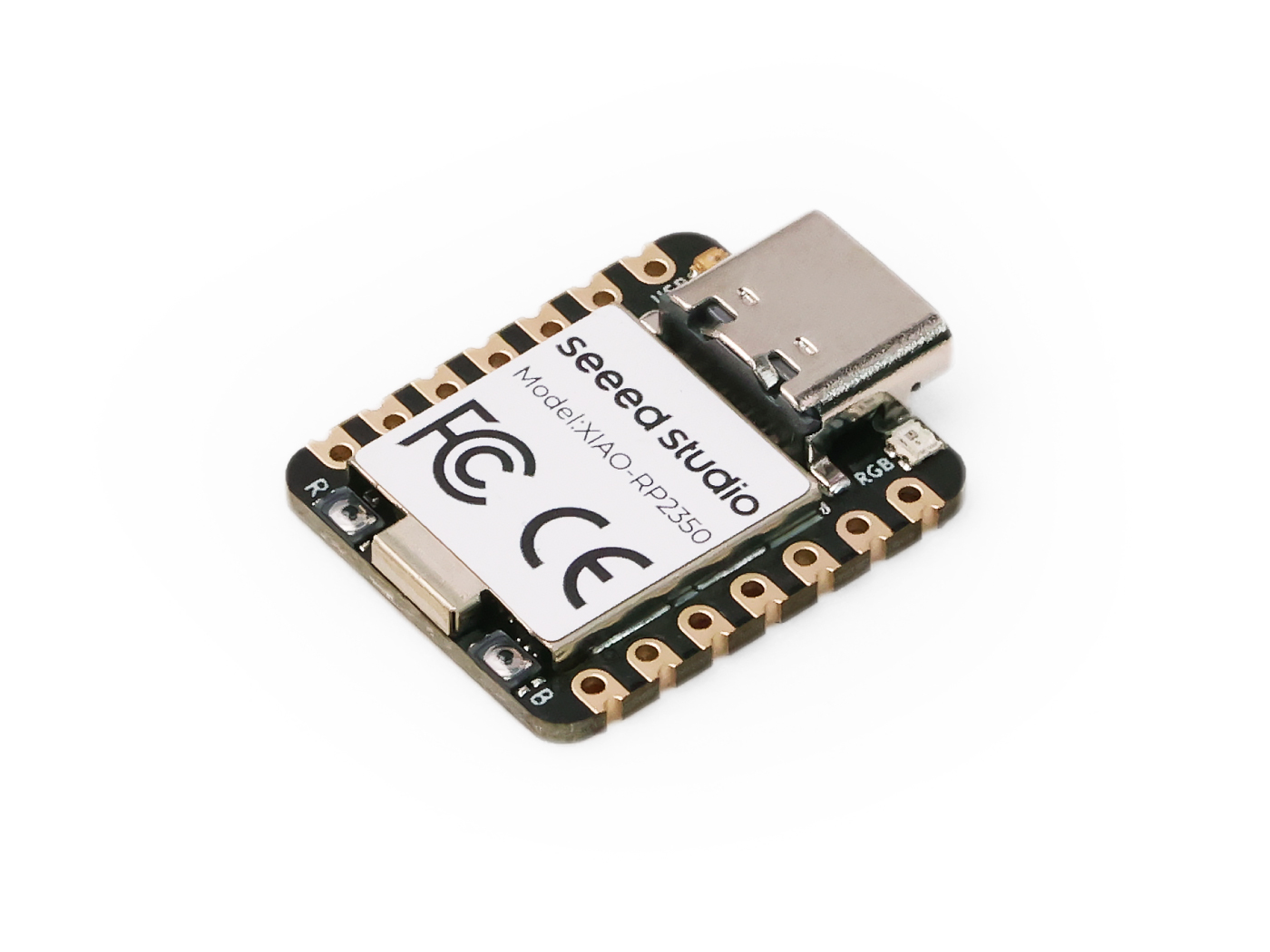
XIAO RP2350 将 Raspberry Pi RP2350(双 Cortex-M33 内核,150MHz 主频,带 FPU,增强的安全性和加密功能)的强大性能封装进经典的 XIAO 外形中。其尺寸仅为 21x17.8mm,具备 19 个多功能 GPIO、一个 RGB LED,以及带有超低 50μA 功耗、电池供电和电池电压直测功能的电池管理系统。得益于 XIAO 生态,XIAO RP2350 兼容多种扩展,包括显示屏、LED 点阵、Grove 模块、CAN Bus、视觉 AI 传感器和毫米波传感器。凭借对 MicroPython、C 和 C++ 的原生支持,XIAO RP2350 非常适合各个水平的开发者,用于构建用于智能控制、可穿戴设备、DIY 键盘等的紧凑型电池供电应用。
支持的平台
由 RP2350 驱动的 XIAO RP2350 支持 Raspberry Pi 提供的 MicroPython 和 C/C++ SDK。这种灵活性使开发者可以根据自己的喜好选择编程语言和开发环境,用于原型设计和开发。
| C/C++ SDK | MicroPython |
|---|---|
入门指南▶️
本页面主要面向 MicroPython 用户。对于有兴趣学习 SDK 编程或进阶用户,建议从 Raspberry Pi Pico-series C/C++ SDK 开始。该指南将帮助你完成环境搭建并通过示例代码入门。此外,你也可以访问 XIAO RP2350 with C/C++ SDK 获取与 XIAO RP2350 相关的更具体说明。
步骤 1:在 XIAO RP2350 上安装 MicroPython
要在 XIAO RP2350 上安装 MicroPython 固件,请按照以下步骤操作:
步骤 1.1 下载 MicroPython 固件:
- 访问 MicroPython Downloads 页面。
- 下载与 XIAO RP2350 兼容的最新
.uf2固件文件。
-
默认固件适用于 ARM 架构,如果你想使用 RISC-V,请在链接中使用对应的固件版本。
-
请确保你使用的是最新固件版本,旧版本固件可能存在各种软件漏洞。
步骤 1.2 进入 BOOTSEL 模式:
你可以通过以下两种方式之一让 XIAO RP2350 进入 BOOTSEL 模式:
- 方法 1:连接电脑之前
- 方法 2:已连接电脑时
- 按住 BOOT 按钮:
在你的 XIAO RP2350 尚未连接电脑时,按住 BOOT 按钮。 - 连接到电脑:
在按住 BOOT 按钮的同时,使用 USB 线将 XIAO RP2350 连接到电脑。 - 松开 BOOT 按钮:
当开发板已经连接到电脑后,你可以松开 BOOT 按钮。此时 XIAO RP2350 应已进入 BOOTSEL 模式,你的电脑会将其识别为一个可移动存储设备。
- 按住 BOOT 按钮:
在 XIAO RP2350 已经连接到电脑的情况下,按住 BOOT 按钮。 - 点击 RESET 按钮:
在仍然按住 BOOT 按钮时,按下并松开 RESET 按钮,在上图中它位于开发板右下角并标有 "B"。 - 松开 BOOT 按钮:
按下 RESET 按钮后,松开 BOOT 按钮。此时 XIAO RP2350 应已进入 BOOTSEL 模式,你的电脑会将其识别为一个可移动存储设备。
步骤 1.3 安装固件:
- 将下载好的
.uf2文件拖放到 XIAO RP2350 的可移动存储盘中。 - 文件复制完成后,开发板会自动重启,即完成固件安装。
步骤 2:安装 Thonny IDE
MicroPython 是一种类似于 Python 的解释型语言。但与 Python 不同的是,MicroPython 直接运行在硬件(裸机)上,提供交互式命令行(REPL)以立即执行命令,同时也可以从内置文件系统运行和导入脚本。
要连接 XIAO RP2350 开发板并开始编写、运行 Python 代码,你可以使用任何支持串口连接的终端工具,例如 minicom、PuTTY、electerm、warp 等。若想获得更友好的使用体验,你可以使用 Thonny,它易于上手、功能集成且界面适合初学者。这样,你就可以在设备上直接编写并运行 Python 代码。
Thonny IDE 是一款对初学者友好的 Python 编辑器,非常适合进行 MicroPython 开发。以下是安装步骤:
-
下载 Thonny:
- 访问 Thonny Download Page。
- 根据你的操作系统(Windows、macOS 或 Linux)选择合适的安装包并下载。
-
安装 Thonny:
- 运行 下载好的安装程序。
- 按照 屏幕上的提示完成安装过程。
-
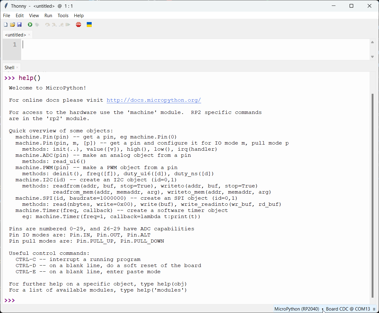
为 MicroPython 配置 Thonny:
- 打开 Thonny IDE。
- 查看 Thonny 窗口的右下角。
- 点击 interpreter 选择区域。
- 在下拉菜单中选择 'MicroPython (RP2040)'。
- 确保选择了正确的 Port——Thonny 通常会自动检测。
现在,你已经可以使用 Thonny IDE 向 XIAO RP2350 编写并上传 MicroPython 代码了!
- Thonny IDE
- PuTTY Console
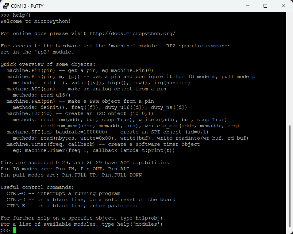
如果你的设备已经准备好运行 MicroPython,那我们就从一个简单的项目开始:
让它闪起来!✨
让开发板点亮并闪烁一个 LED 通常是大家运行的第一个程序,XIAO RP2350 也不例外。
根据原理图,XIAO RP2350 上的 USER LED(黄色 LED)连接到 GPIO25/D19。
对于所有 XIAO 系列开发板,当将 USER LED 设置为 low level 时会点亮,设置为 high level 时会熄灭。
- Blink
- Fading a LED
from machine import Pin # Import the Pin class from the machine module
from time import sleep  # Import the sleep function from the time module

# Initialize GPIO25 as an output pin, which controls the USER LED
led = Pin(25, Pin.OUT)

# Turn off the LED initially
led.value(1) # led.on() -> high level -> light off
sleep(0.5) # Wait for 0.5 seconds

# Turn on the LED
led.value(0) # led.off() -> low level -> light on
sleep(0.5) # Wait for 0.5 seconds

# Enter an infinite loop
while True:
    # Toggle the LED state (on to off or off to on)
    led.toggle()
    # Print the current state of the LED
    print(f"LED {'ON' if led.value() == 0 else 'OFF'}")
    sleep(0.5) # Wait for 0.5 seconds before the next toggle
 |  |
# Example using PWM to fade an LED.

import time
from machine import Pin, PWM

# Construct PWM object, with LED on Pin(25).
pwm = PWM(Pin(25))

# Set the PWM frequency.
pwm.freq(1000)

# Fade the LED in and out a few times.
duty = 0
direction = 1
for _ in range(8 * 256):
    duty += direction
    if duty > 255:
        duty = 255
        direction = -1
    elif duty < 0:
        duty = 0
        direction = 1
    pwm.duty_u16(duty * duty)
    time.sleep(0.001)
当你已经将代码复制到 Thonny IDE 中后,如下图所示,只需点击 Run current script 按钮或按下 F5。这将执行代码片段,你会看到 XIAO RP2350 上的 LED 开始闪烁。
玩转 RGB LED
XIAO RP2350 自带一个可通过 MicroPython 控制的 RGB LED。下面是一个循环显示不同颜色的示例:
import array, time, random
from machine import Pin
import rp2

NUM_LEDS = 1
LED_PIN = 22  # PICO_DEFAULT_WS2812_PIN
POWER_PIN = 23  # PICO_DEFAULT_WS2812_POWER_PIN

# Global brightness variable (0.0 to 1.0)
BRIGHTNESS = 0.1

@rp2.asm_pio(sideset_init=rp2.PIO.OUT_LOW, out_shiftdir=rp2.PIO.SHIFT_LEFT, autopull=True, pull_thresh=24)
def ws2812():
    T1 = 2
    T2 = 5
    T3 = 3
    wrap_target()
    label("bitloop")
    out(x, 1)               .side(0)    [T3 - 1]
    jmp(not_x, "do_zero")   .side(1)    [T1 - 1]
    jmp("bitloop")          .side(1)    [T2 - 1]
    label("do_zero")
    nop()                   .side(0)    [T2 - 1]
    wrap()

# Set up the power pin
power_pin = Pin(POWER_PIN, Pin.OUT)
power_pin.value(1)  # Turn on power to the LED

# Create the StateMachine with the ws2812 program, outputting on LED_PIN
sm = rp2.StateMachine(0, ws2812, freq=8_000_000, sideset_base=Pin(LED_PIN))

# Start the StateMachine, it will wait for data on its FIFO.
sm.active(1)

def set_led_color(color):
    sm.put(array.array("I", [color]), 8)

def random_color():
    return random.randint(0, 255) | (random.randint(0, 255) << 8) | (random.randint(0, 255) << 16)

def interpolate(color1, color2, factor):
    r1, g1, b1 = color1 & 255, (color1 >> 8) & 255, (color1 >> 16) & 255
    r2, g2, b2 = color2 & 255, (color2 >> 8) & 255, (color2 >> 16) & 255
    r = int(r1 + factor * (r2 - r1))
    g = int(g1 + factor * (g2 - g1))
    b = int(b1 + factor * (b2 - b1))
    return (b << 16) | (g << 8) | r

def apply_brightness(color, brightness):
    r, g, b = color & 255, (color >> 8) & 255, (color >> 16) & 255
    r = int(r * brightness)
    g = int(g * brightness)
    b = int(b * brightness)
    return (b << 16) | (g << 8) | r

print("Starting random color transitions with adjustable brightness...")

# Main loop
current_color = random_color()
while True:
    next_color = random_color()
    for i in range(100):  # 100 steps for smooth transition
        transition_color = interpolate(current_color, next_color, i / 100)
        final_color = apply_brightness(transition_color, BRIGHTNESS)
        set_led_color(final_color)
        time.sleep_ms(20)  # Adjust this value to change transition speed
    current_color = next_color

    # Optionally, you can change the brightness here for demo purposes
    # BRIGHTNESS = random.random()  # This will set a random brightness each cycle
电池与电源管理
是否可以在没有额外元件的情况下读取电池电压?可以,在 XIAO RP2350 上,这比以往更简单。在之前的 XIAO 家族成员中,例如 XIAO ESP32C3,读取电池电压需要通过电阻手动连接到 A0。
但在 XIAO RP2350 上,这个过程被简化了。你现在可以直接使用 A3/GPIO29 引脚来读取电池电压等级,从而简化你的设计和开发。只要记得将 GPIO19 引脚设置为高电平,因为这是启用电池电量读取所必需的。
按照下面的代码片段操作,使用 Pico SDK 读取电池电压:
- MicroPython
- C/C++ SDK
from machine import Pin, ADC
import time

# Function to initialize the GPIO pin for enabling battery voltage reading
def init_gpio():
    enable_pin = Pin(19, Pin.OUT)
    enable_pin.value(1)  # Set the pin to high to enable battery voltage reading

def main():
    print("ADC Battery Example - GPIO29 (A3)")

    init_gpio()  # Initialize the enable pin
    adc = ADC(Pin(29))  # Initialize the ADC on GPIO29

    conversion_factor = 3.3 / (65535)  # Conversion factor for 12-bit ADC and 3.3V reference

    while True:
        result = adc.read_u16()  # Read the ADC value
        voltage = result * conversion_factor * 2  # Calculate the voltage, considering the voltage divider (factor of 2)
        print("Raw value: 0x{:03x}, voltage: {:.2f} V".format(result, voltage))
        time.sleep(0.5)  # Delay for 500 milliseconds

if __name__ == '__main__':
    main()
#include <stdio.h>
#include "pico/stdlib.h"
#include "hardware/gpio.h"
#include "hardware/adc.h"

// Function to initialize the GPIO pin for enabling battery voltage reading
void init_gpio() {
    const int enable_pin = 19; // Pin to enable battery voltage reading

    gpio_init(enable_pin); // Initialize the pin
    gpio_set_dir(enable_pin, GPIO_OUT); // Set the pin as output
    gpio_put(enable_pin, 1); // Set the pin to high to enable battery voltage reading
}

int main() {
    stdio_init_all(); // Initialize standard input/output
    printf("ADC Battery Example - GPIO29 (A3)\n");

    init_gpio(); // Initialize the enable pin
    adc_init(); // Initialize the ADC

    // Initialize the ADC GPIO pin (GPIO29)
    adc_gpio_init(29);
    // Select ADC input 3 (corresponding to GPIO29)
    adc_select_input(3);

    while (1) {
        // 12-bit conversion, assume max value == ADC_VREF == 3.3 V
        const float conversion_factor = 3.3f / (1 << 12); // Conversion factor for 12-bit ADC and 3.3V reference
        uint16_t result = adc_read(); // Read the ADC value
        // Calculate the voltage, considering the voltage divider (factor of 2)
        printf("Raw value: 0x%03x, voltage: %f V\n", result, result * conversion_factor * 2);
        sleep_ms(500); // Delay for 500 milliseconds
    }
}
扩展与应用
XIAO 系列 拥有非常丰富的外设和外设配件供你学习和使用,无论你是想要一个可以完美交互的彩色屏幕,还是一个集成了明亮简洁 RGB 灯的板子等等,都在等你来探索。
作为 XIAO 家族的一员,XIAO RP2350 也同样如此。当然,为了更好地利用引出的额外引脚,新的 外设和扩展板 将会不断推出,充分发挥其诞生之初所追求的性能。
- 🌟 通过配件扩展
了解与 XIAO 家族兼容的各种扩展件和模块,从显示屏、LED 点阵到 Grove 模块和传感器,并学习它们如何增强你的项目。
社区与学习
此外,深入活跃的 Raspberry Pi 社区,拓展你的知识并发现新的项目灵感。利用社区共享的资源、论坛和教程,提升你使用 XIAO RP2350 的体验。除了 Seeed Studio Wiki 之外,这里还有一些推荐的学习平台:
- Raspberry Pi Documentation:获取关于 RP2350 可靠且最新的资料。
- Raspberry Pi Forums:与其他爱好者交流、提问并分享你的项目。
- XIAO GitHub Repository:浏览官方 XIAO 仓库,获取更集中化的文档,并与我们的团队有更多互动,加入我们!
- r/embedded on Reddit:加入嵌入式系统社区,分享见解并讨论各类话题。
- Pico Topic on GitHub:探索与 Pico 相关的仓库和讨论。
- Hackster.io:发现与各类硬件平台相关的项目和教程,包括 XIAO 和 Raspberry Pi。
- Instructables:查找使用 XIAO 和其他硬件进行创作的 DIY 项目和分步指南。
- Element14 Community:参与与电子和嵌入式系统相关的讨论、网络研讨会和项目。
此外,也非常欢迎你在我们的 Seeed Studio Discord 和 Seeed Studio Forum 上分享你的项目。这些平台为你提供了与其他创客交流、获取反馈和寻找灵感的绝佳机会。无论你是需要帮助排查问题、想展示你的最新作品,还是只是希望成为一个互相支持的社区的一员,Seeed Studio 的 Discord 和论坛 都是参与和协作的理想之地。
技术支持与产品讨论
感谢你选择我们的产品!我们将为你提供多种支持,确保你在使用我们产品的过程中尽可能顺利。我们提供多种沟通渠道,以满足不同的偏好和需求。