Vision AI V2 数据的 RS485 传输
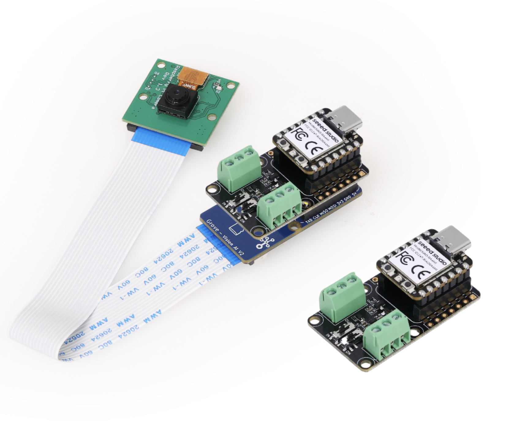
如果您需要将 RS485 扩展板与 Vision AI V2 配合使用,您需要在 RS485 扩展板的背面重新焊接新的排针。
硬件准备
| Seeed Studio XIAO ESP32S3 | Grove Vision AI V2 | OV5647-62 FOV Camera Module for Raspberry Pi 3B+4B | Seeed Studio XIAO RS485-Expansion-Board |
|---|---|---|---|
 |  |  |  |
连接方法
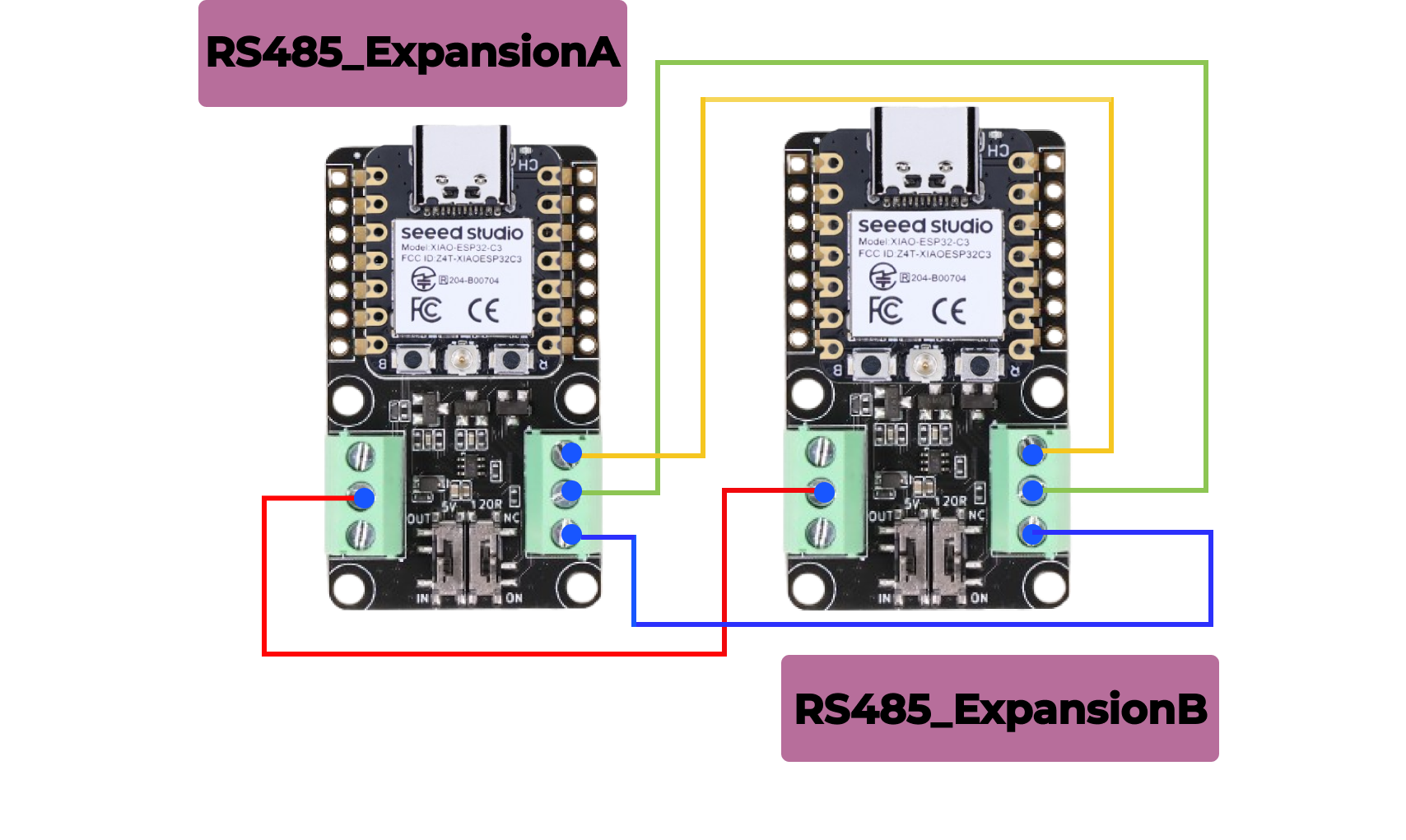
首先,准备两个扩展板、两个 XIAO 系列开发板和一个 Vision AI V2,根据图示连接相应的引脚,本例程使用 XIAO ESP32C3 作为演示。
步骤 1. 准备两个 RS485 扩展板和两个 XIAO 系列开发板,按照下图连接引脚
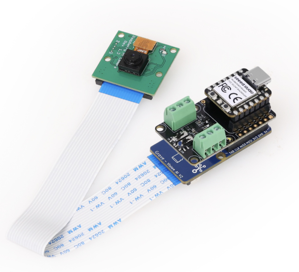
步骤 2. 准备 Vision AI V2 安装在两个 RS485 扩展板中的一个的背面作为发送端
如果您是第一次使用 RS485 扩展板并且不确定如何接线,请点击此链接(https://wiki.seeedstudio.com/cn/XIAO-RS485-Expansion-Board/)
如果您不知道如何烧录模型和添加模型输出代码,请点击此链接(https://wiki.seeedstudio.com/cn/grove_vision_ai_v2_software_support/),它会详细告诉您每个步骤
为了更好的后续使用,请不要跳过这两个步骤!
软件准备
发送端代码
#include <Seeed_Arduino_SSCMA.h>

#ifdef ESP32
#include <HardwareSerial.h>

HardwareSerial Serial3(1);

// Define two Serial devices mapped to the two internal UARTs
HardwareSerial atSerial(0);

#else
#define atSerial Serial1
#endif

#define enable_pin D2 // Define the enable pin as D2

SSCMA AI;

void setup()
{
    Serial3.begin(115200, SERIAL_8N1, 7, 6); // Initialize Serial3 with 115200 baud rate, 8 data bits, no parity, 1 stop bit
    Serial.begin(9600); // Initialize Serial for debugging output
    AI.begin(&atSerial); // Initialize the AI module with the AT serial

    pinMode(enable_pin, OUTPUT); // Set the enable pin as an output
    digitalWrite(enable_pin, HIGH); // Set the enable pin to high to enable the AI module
}

void loop()
{
    if (!AI.invoke(1, false, true)) { // Invoke the AI to start processing

        Serial.println("invoke success"); // Print success message

        // Print performance metrics
        Serial.print("perf: prepocess=");
        Serial.print(AI.perf().prepocess);
        Serial.print(", inference=");
        Serial.print(AI.perf().inference);
        Serial.print(", postpocess=");
        Serial.println(AI.perf().postprocess);

        // Loop through detected boxes
        for (int i = 0; i < AI.boxes().size(); i++) {
            Serial.print("Box[");
            Serial.print(i);
            Serial.print("] target=");
            Serial.print(AI.boxes()[i].target);
            Serial.print(", score=");
            Serial.print(AI.boxes()[i].score);
            Serial.print(", x=");
            Serial.print(AI.boxes()[i].x);
            Serial.print(", y=");
            Serial.print(AI.boxes()[i].y);
            Serial.print(", w=");
            Serial.print(AI.boxes()[i].w);
            Serial.print(", h=");
            Serial.println(AI.boxes()[i].h);
        }

        // Loop through detected classes
        for (int i = 0; i < AI.classes().size(); i++) {
            Serial.print("Class[");
            Serial.print(i);
            Serial.print("] target=");
            Serial.println(AI.classes()[i].target);

            // Check the target class and send corresponding status
            if (AI.classes()[i].target == 0) {
                String status_a = "no people detected"; // Define status for no people detected
                Serial3.println(status_a); // Send status to Serial3
                Serial.println(status_a); // Print status to Serial monitor
            } else if (AI.classes()[i].target == 1) {
                String status_b = "people detected"; // Define status for people detected
                Serial3.println(status_b); // Send status to Serial3
                Serial.println(status_b); // Print status to Serial monitor
            }
        }
        delay(1000); // Wait for 1 second before the next loop iteration
    }
}
代码详细功能
-
库文件包含
- 包含
HardwareSerial库以使用硬件串口功能。 - 包含
Seeed_Arduino_SSCMA库用于 AI 模块控制。
- 包含
-
串口对象创建
HardwareSerial Serial3(1);
HardwareSerial atSerial(0);
创建 Serial3 和 atSerial 对象用于串口通信。
-
AI 对象创建
SSCMA AI;创建 SSCMA 类的实例用于 AI 处理。
-
性能指标
Serial.print("perf: prepocess=");
Serial.print(AI.perf().prepocess);
Serial.print(", inference=");
Serial.print(AI.perf().inference);
Serial.print(", postpocess=");
Serial.println(AI.perf().postprocess);
打印 AI 处理阶段的性能指标:预处理、推理和后处理。
-
检测框循环
for (int i = 0; i < AI.boxes().size(); i++) {
    Serial.print("Box[");
    Serial.print(i);
    Serial.print("] target=");
    Serial.print(AI.boxes()[i].target);
    Serial.print(", score=");
    Serial.print(AI.boxes()[i].score);
    Serial.print(", x=");
    Serial.print(AI.boxes()[i].x);
    Serial.print(", y=");
    Serial.print(AI.boxes()[i].y);
    Serial.print(", w=");
    Serial.print(AI.boxes()[i].w);
    Serial.print(", h=");
    Serial.println(AI.boxes()[i].h);
}
循环遍历检测到的框并打印其详细信息,包括目标、分数和边界框坐标。
-
检测类别循环
for (int i = 0; i < AI.classes().size(); i++) {
   Serial.print("Class[");
   Serial.print(i);
   Serial.print("] target=");
   Serial.println(AI.classes()[i].target);
循环遍历检测到的类别并打印其目标。
-
宏定义
pinMode(enable_pin, OUTPUT); // Set the enable pin as an output
digitalWrite(enable_pin, LOW);
将使能引脚定义为 D2。
-
发送消息
// Check the target class and send corresponding status
if (AI.classes()[i].target == 0) {
    String status_a = "no people detected"; // Define status for no people detected
    Serial3.println(status_a); // Send status to Serial3
    Serial.println(status_a); // Print status to Serial monitor
} else if (AI.classes()[i].target == 1) {
    String status_b = "people detected"; // Define status for people detected
    Serial3.println(status_b); // Send status to Serial3
    Serial.println(status_b); // Print status to Serial monitor
}
判断是否检测到人员,如果检测到人员则向接收端发送 PEOPLE DETECTED,如果未检测到人员则向接收端发送 NO PEOPLE DETECTED。
接收端代码
#include <HardwareSerial.h>

HardwareSerial Serial3(1); // Use UART2
#define enable_pin D2 // Define the enable pin as D2


void setup() {
  Serial.begin(115200); // Initialize the hardware serial with a baud rate of 115200
  Serial3.begin(115200, SERIAL_8N1, 7, 6); // Initialize Serial3 with 115200 baud rate, 8 data bits, no parity, 1 stop bit (RX=D4(GPIO4), TX=D5(GPIO5))

  // Wait for the hardware serial to be ready
  while(!Serial3);
  while(!Serial); // This line is generally unnecessary as Serial.begin() is ready immediately

  pinMode(enable_pin, OUTPUT); // Set the enable pin as an output
  digitalWrite(enable_pin, LOW); // Set the enable pin to low to enable the device
}

void loop() {
    delay(100); // Delay for 100 milliseconds
    // Check if there is data available from the hardware serial
    if (Serial3.available()) {
        String receivedData = Serial3.readStringUntil('\n'); // Read string until newline character
        Serial.print("Received data: "); // Print label for received data
        Serial.println(receivedData); // Directly print the received data
    }
}
代码详细功能
-
库包含
- 包含
HardwareSerial库以使用硬件串口功能。
- 包含
-
串口对象创建
- 使用 UART2 创建一个
Serial3对象。
- 使用 UART2 创建一个
-
宏定义
pinMode(enable_pin, OUTPUT); // Set the enable pin as an output
digitalWrite(enable_pin, LOW);
将使能引脚定义为 D2。
-
设置函数
Serial3.begin(115200, SERIAL_8N1, 7, 6);初始化主串口和 Serial3,设置波特率、数据位等。这是与 vision ai v2 通信以传输数据的串口。
while(!Serial3);
while(!Serial);
等待所有串口准备就绪,将使能引脚设置为输出,并将其拉低以启用设备。
-
循环函数
if (Serial3.available());:每 100 毫秒检查一次 Serial3 上是否有可用数据。String receivedData = Serial3.readStringUntil('\n');:如果有可用数据,读取直到换行符并将接收到的数据打印到主串口。
-
打印结果
Serial.print("Received data: ");
Serial.println(receivedData);
打印发送方的消息
结果图表
然而,当摄像头识别到人时会发送 "people detected",当没有识别到人时会发送 "no people detected",接收方将在串口上显示发送方的识别结果。

技术支持与产品讨论
感谢您选择我们的产品!我们在这里为您提供不同的支持,以确保您使用我们产品的体验尽可能顺畅。我们提供多种沟通渠道,以满足不同的偏好和需求。