Arduino 菜谱:RTC、低功耗、音频与触摸(reTerminal E 系列)
如果你想在搭建开发环境之前,快速预览项目效果或体验基础示例固件,请打开 reTerminal E-Series Firmware Hub。你可以选择受支持的 reTerminal E 系列设备,并直接通过浏览器烧录示例固件。
- Arduino 菜谱:电子纸显示屏 —— 在电子纸屏幕上渲染文本、图形和图像。
- Arduino 菜谱:板载外设 —— LED、蜂鸣器、按键、SHT4x 传感器、电池监测、microSD 卡以及 SD 卡图像处理流程。
介绍
这是 reTerminal E 系列的第二篇外设菜谱。第一篇外设菜谱涵盖了基础 I/O 外设(LED、蜂鸣器、按键、SHT4x、电池、SD 卡),而本页将深入介绍四个更高级的主题:
- 实时时钟(RTC) —— 板载 PCF8563 RTC 芯片由 CR1220 纽扣电池供电,即使主电池被移除也能持续计时。
- 低功耗模式 —— 深度睡眠、轻度睡眠以及 GPIO 唤醒策略,可将电池续航从数天延长到数月。
- PDM 麦克风 —— 通过板载 PDM 数字麦克风采集音频(仅限 E1001 / E1002 / E1003;E1004 不带麦克风),并将 WAV 文件保存到 microSD 卡。
- 触摸屏 —— 在 E1003(10.3" 型号)上使用板载电容触摸面板在电子纸显示屏上绘制点。只有 E1003 配备触摸面板。
本菜谱中的所有示例草图均来自 OSHW-reTerminal-Series-E-D 仓库。RTC、低功耗和麦克风示例草图无需额外安装库——全部使用 ESP32 内置 API。触摸示例草图需要 Seeed_GFX 库。
所需材料
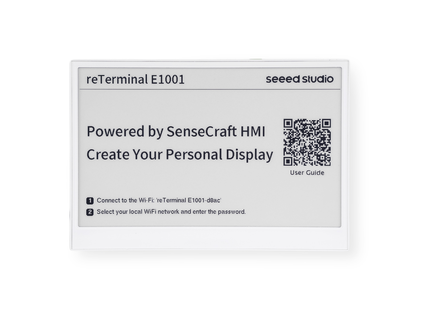
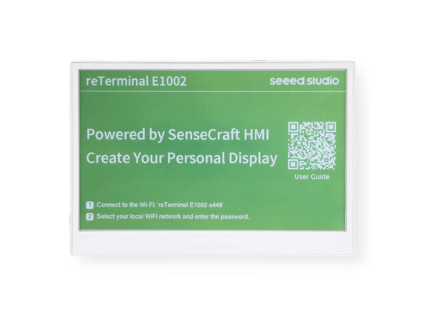
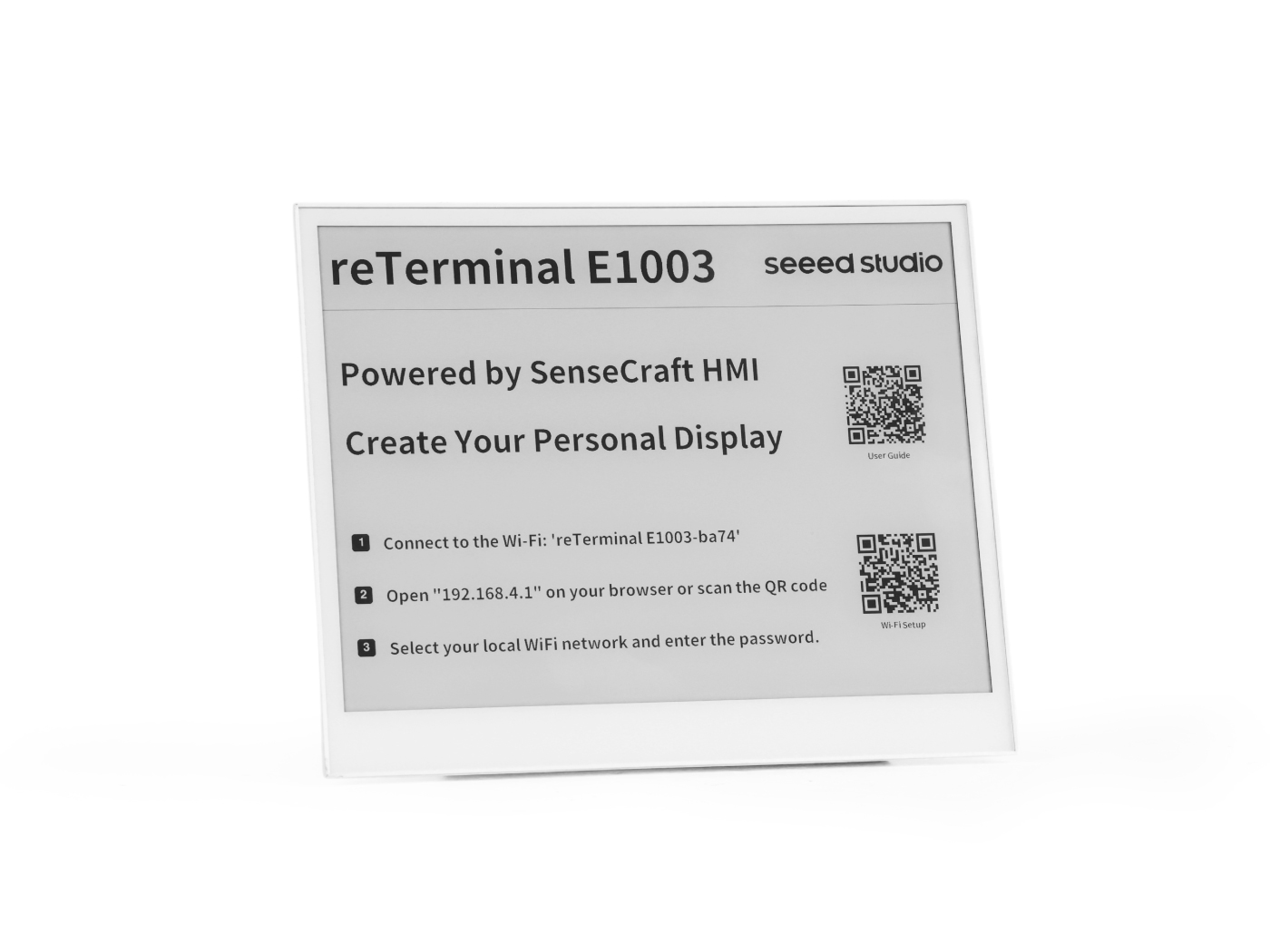
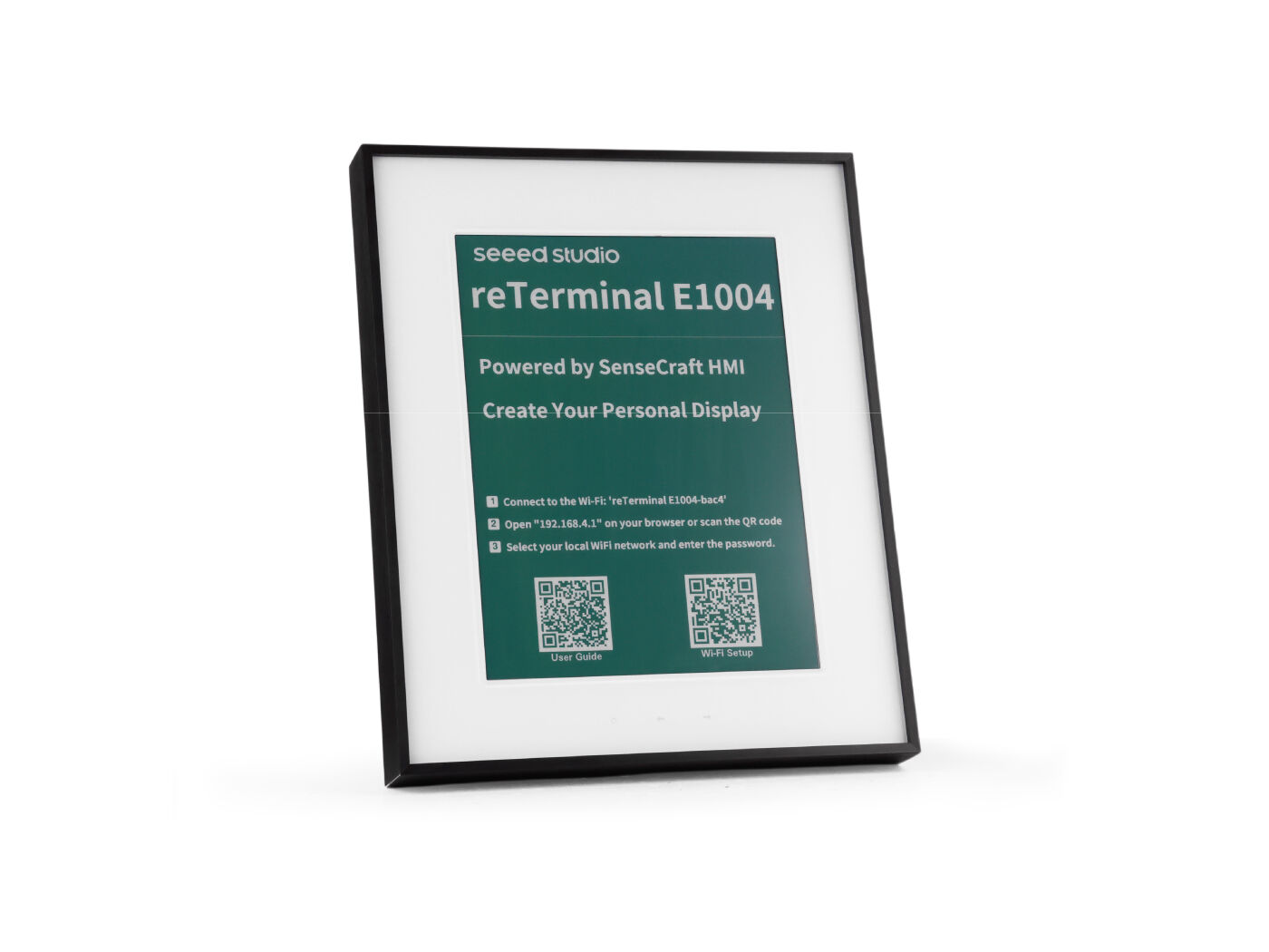
本菜谱适用于 reTerminal E 系列。请选择你手头拥有的任意设备:
前置条件
在运行下面任意示例之前,你应当已经完成以下准备:
- 已安装 Arduino IDE,并安装好 ESP32 开发板包(PDM 麦克风需 ≥ 3.0 版本),且已选择 XIAO_ESP32S3 开发板。
- 在 Tools 菜单中将 PSRAM 设置为 OPI PSRAM,将 Flash 设置为 8 MB。
- 准备好一根可用的 USB-C 数据线,并选择正确的串口。
- 已验证可以向设备烧录基础示例草图——如果尚未完成,请参考 Arduino 菜谱:电子纸显示屏中的环境搭建部分。
本菜谱中的所有示例草图都会通过 Serial1 在 GPIO44(RX)/ GPIO43(TX) 引脚以 115200 波特率输出调试信息——这是通过 USB-UART 桥接的串口,而不是 Arduino IDE 自动打开的 USB-CDC Serial。请打开 Arduino 串口监视器,并选择匹配的端口和波特率以便查看输出。
硬件兼容性概览
本菜谱中的功能并非在四个型号上全部可用。下表总结了各型号可用的功能:
| 功能 | E1001 | E1002 | E1003 | E1004 |
|---|---|---|---|---|
| PCF8563 RTC(外置,I2C 0x51,CR1220 备份) | ✅ | ✅ | ✅ | ✅ |
| 深度睡眠 / 轻度睡眠 | ✅ | ✅ | ✅ | ✅ |
| 按键唤醒(KEY0) | ✅ | ✅ | ✅ | ✅ |
| PDM 麦克风录音 | ✅ | ✅ | ✅ | ❌ |
| 电容触摸面板 | ❌ | ❌ | ✅ | ❌ |
实时时钟(RTC)
每一款 reTerminal E 系列型号都集成了一颗来自 NXP 的板载 PCF8563 实时时钟芯片,配有独立的 32.768 kHz 晶振和一个 CR1220 纽扣电池座,即使主电池被移除或完全耗尽,也能持续计时。
设备出厂时不附带 CR1220 纽扣电池。你需要单独购买一颗 CR1220 电池并安装,RTC 才能在断电后保持时间。
安装 CR1220 电池
CR1220 电池座位于 PCB 背面。不同型号的拆机步骤略有差异:
- E1001 / E1002
- E1003
- E1004
步骤 1 — 关闭设备电源
断开 USB-C 线缆,确保设备完全关机。
步骤 2 — 拆下后盖
卸下背板上的四颗螺丝,取下后盖以露出 PCB。
步骤 3 — 找到电池座
在 PCB 上找到 CR1220 纽扣电池座(标记为 BT2 或 CR1220)。
步骤 4 — 安装电池
将 CR1220 电池放入电池座中,确保 正极(+)朝上。轻轻按压,直到听到卡入的声音。
步骤 5 — 重新组装
将后盖装回并拧紧四颗螺丝。RTC 现在由电池供电备份,即使主电源断开也能保持时间。
步骤 1 — 关闭设备电源
断开 USB-C 线缆,并确保设备已完全关机。
步骤 2 — 拆下后盖
卸下背板上的螺丝,抬起后盖以露出 PCB。
步骤 3 — 找到电池座
在 PCB 上找到 CR1220 纽扣电池座(标记为 BT2 或 CR1220)。
步骤 4 — 安装电池
将 CR1220 电池放入电池座中,确保正极(+)朝上。轻轻按压,直到听到卡入到位的声音。
步骤 5 — 重新组装
将后盖装回并拧紧螺丝。RTC 现在由电池供电备份,即使主电源断开也能保持时间。
步骤 1 — 关闭设备电源
断开 USB-C 线缆,并确保设备已完全关机。
步骤 2 — 拆下后盖
卸下背板周围的螺丝,小心抬起后盖以露出 PCB。
步骤 3 — 找到电池座
在 PCB 上找到 CR1220 纽扣电池座(标记为 BT2 或 CR1220)。
步骤 4 — 安装电池
将 CR1220 电池放入电池座中,确保正极(+)朝上。轻轻按压,直到听到卡入到位的声音。
步骤 5 — 重新组装
将后盖装回并拧紧所有螺丝。RTC 现在由电池供电备份,即使主电源断开也能保持时间。
硬件概览
| 参数 | 数值 |
|---|---|
| 芯片 | PCF8563M/TR (NXP) |
| 总线 | I2C — 地址 0x51(芯片内部固定) |
| SCL | GPIO20 |
| SDA | GPIO19 |
| 晶振 | 32.768 kHz(OSCI / OSCO 引脚) |
| 后备电池 | CR1220 纽扣电池 — 在主电源移除时保持时间 |
| VL 标志 | 当后备电池电压过低时由芯片置位;表示时间不可靠 |
完整示例:RTC_PCF8563
完整示例可在代码仓库中获取:examples/RTC_PCF8563/RTC_PCF8563.ino。
点击展开完整的 RTC_PCF8563.ino 代码
// ============================================================
// USER CONFIGURATION
// ============================================================

// --- How to set the initial time ---
//
// OPTION A — Compile-time (recommended):
//   Uncomment USE_COMPILE_TIME.  The C compiler embeds __DATE__ / __TIME__
//   (the exact moment you clicked "Upload") into the binary automatically.
//   No need to type the date by hand — just compile and flash.
//
#define USE_COMPILE_TIME
//
// OPTION B — Manual:
//   Comment out USE_COMPILE_TIME above, then fill in the values below.
//   INITIAL_YEAR must be in the range 2000–2099.
#define INITIAL_YEAR   2026
#define INITIAL_MONTH     5   // 1–12
#define INITIAL_DAY      26   // 1–31
#define INITIAL_HOUR     14   // 0–23
#define INITIAL_MIN       0   // 0–59
#define INITIAL_SEC       0   // 0–59

// --- When to write the time ---
//
// You do NOT need to touch anything here for normal use.
//
// How it works automatically:
//   • New board / battery just replaced → PCF8563 sets VL=1 internally
//     → code detects VL=1 at boot → writes the initial time once → done.
//   • Every reboot after that (battery healthy, VL=0)
//     → stored time is kept, nothing is overwritten.
//
// FORCE_SET_TIME is only for manual re-calibration (e.g. correcting drift).
// If you uncomment it, the clock is overwritten on EVERY boot — make sure
// to comment it out again and re-flash right after calibrating.
//
// #define FORCE_SET_TIME

// ============================================================
// END OF USER CONFIGURATION — no need to edit below this line
// ============================================================

#include <Wire.h>
#include <time.h>
#include <sys/time.h>

// ============================================================
// RtcTime — carries all date/time fields returned by rtcGetTime().
//
// Defined here, right after the #includes, so that Arduino IDE's
// automatic function-prototype injection (which is inserted after
// the last #include) can see the type before using it in prototypes
// like  static bool rtcGetTime(RtcTime &rt).
// ============================================================
struct RtcTime {
    int  year;       // full year (e.g. 2026)
    int  month;      // 1–12
    int  day;        // 1–31
    int  weekday;    // 0=Sunday … 6=Saturday
    int  hour;       // 0–23
    int  minute;     // 0–59
    int  second;     // 0–59
    bool voltageOK;  // false → VL flag set, battery was drained, time unreliable
};

// ---------- Serial debug (carrier USB-UART bridge) ----------
#define PIN_SERIAL_RX   44
#define PIN_SERIAL_TX   43
#define LOG             Serial1

// ---------- I2C pins (identical on all E1001 / E1002 / E1003 / E1004) --------
#define PIN_I2C_SCL     20   // ESP_IO20 / I2C0_SCL
#define PIN_I2C_SDA     19   // ESP_IO19 / I2C0_SDA

// ---------- PCF8563 I2C address (7-bit, fixed in hardware) -------------------
#define PCF8563_ADDR    0x51

// ---------- PCF8563 register map (only the registers used here) --------------
#define REG_CTRL1       0x00   // Control/Status 1 — bit5 STOP halts the clock
#define REG_CTRL2       0x01   // Control/Status 2
#define REG_SECONDS     0x02   // bit7 = VL (voltage-low flag); bits6:0 = seconds
#define REG_MINUTES     0x03   // bits6:0 = minutes
#define REG_HOURS       0x04   // bits5:0 = hours
#define REG_DAYS        0x05   // bits5:0 = day-of-month
#define REG_WEEKDAYS    0x06   // bits2:0 = weekday (0=Sunday)
#define REG_MONTHS      0x07   // bit7 = century (0→2000s, 1→1900s); bits4:0 = month
#define REG_YEARS       0x08   // bits7:0 = year within century (BCD, 00–99)
#define REG_CLKOUT      0x0D   // CLKOUT control — bit7 FE enables clock output pin

// ============================================================
// BCD ↔ decimal conversion
// The PCF8563 stores all time fields in BCD (Binary-Coded Decimal):
//   e.g. decimal 26 → upper nibble=2, lower nibble=6 → 0x26
// ============================================================
static inline uint8_t bcdToDec(uint8_t bcd)
{
    return static_cast<uint8_t>(((bcd >> 4) * 10U) + (bcd & 0x0FU));
}

static inline uint8_t decToBcd(uint8_t dec)
{
    return static_cast<uint8_t>(((dec / 10U) << 4) | (dec % 10U));
}

// ============================================================
// I2C read / write helpers
// ============================================================

// Read `len` consecutive registers starting at `reg` into `buf`.
// Uses a repeated-START (no STOP between write and read) as required by the
// PCF8563 data sheet.
static bool rtcReadRegs(uint8_t reg, uint8_t *buf, size_t len)
{
    Wire.beginTransmission(PCF8563_ADDR);
    Wire.write(reg);
    if (Wire.endTransmission(false) != 0) return false;   // repeated START

    const uint8_t received = Wire.requestFrom(static_cast<uint8_t>(PCF8563_ADDR),
                                              static_cast<uint8_t>(len));
    if (received != len) return false;

    for (size_t i = 0; i < len; i++) {
        buf[i] = static_cast<uint8_t>(Wire.read());
    }
    return true;
}

// Write a single register.
static bool rtcWriteReg(uint8_t reg, uint8_t value)
{
    Wire.beginTransmission(PCF8563_ADDR);
    Wire.write(reg);
    Wire.write(value);
    return Wire.endTransmission() == 0;
}

// ============================================================
// PCF8563 API
// ============================================================

// Check whether the chip responds on the I2C bus.
static bool rtcProbe()
{
    Wire.beginTransmission(PCF8563_ADDR);
    return Wire.endTransmission() == 0;
}

// Clear the STOP bit so the oscillator runs, and disable the CLKOUT pin
// (saves a small amount of power when the clock output is not needed).
static bool rtcInit()
{
    if (!rtcWriteReg(REG_CTRL1, 0x00)) return false;   // STOP=0 → run
    if (!rtcWriteReg(REG_CTRL2, 0x00)) return false;   // clear alarm/timer flags
    if (!rtcWriteReg(REG_CLKOUT, 0x00)) return false;  // FE=0 → disable CLKOUT
    return true;
}

// Return false if the voltage-low flag is set (time data is unreliable).
static bool rtcVoltageOK()
{
    uint8_t sec = 0;
    if (!rtcReadRegs(REG_SECONDS, &sec, 1)) return false;
    return (sec & 0x80U) == 0U;   // VL bit = 0 means voltage has been OK
}

// Write date and time to the RTC.
// `year` must be in the range 2000–2099.
// Weekday is computed automatically from the supplied date.
static bool rtcSetTime(int year, int month, int day,
                       int hour, int minute, int second)
{
    if (year  < 2000 || year  > 2099) return false;
    if (month < 1    || month > 12  ) return false;
    if (day   < 1    || day   > 31  ) return false;
    if (hour  < 0    || hour  > 23  ) return false;
    if (minute < 0   || minute > 59 ) return false;
    if (second < 0   || second > 59 ) return false;

    // Use mktime() to derive the weekday (0=Sunday) from the calendar date.
    struct tm t = {};
    t.tm_year = year - 1900;
    t.tm_mon  = month - 1;
    t.tm_mday = day;
    mktime(&t);   // fills t.tm_wday

    // Write all 7 time registers in one burst starting at REG_SECONDS.
    // The PCF8563 auto-increments the internal address pointer after each byte.
    Wire.beginTransmission(PCF8563_ADDR);
    Wire.write(REG_SECONDS);
    Wire.write(decToBcd(static_cast<uint8_t>(second)));
    Wire.write(decToBcd(static_cast<uint8_t>(minute)));
    Wire.write(decToBcd(static_cast<uint8_t>(hour)));
    Wire.write(decToBcd(static_cast<uint8_t>(day)));
    Wire.write(static_cast<uint8_t>(t.tm_wday));         // weekday is not BCD
    Wire.write(decToBcd(static_cast<uint8_t>(month)));   // century bit = 0 → 2000s
    Wire.write(decToBcd(static_cast<uint8_t>(year % 100)));
    return Wire.endTransmission() == 0;
}

// Read the current date and time from the RTC into an RtcTime struct.
static bool rtcGetTime(RtcTime &rt)
{
    uint8_t raw[7] = {};
    // Burst-read 7 bytes: seconds, minutes, hours, days, weekdays, months, years
    if (!rtcReadRegs(REG_SECONDS, raw, 7)) return false;

    rt.voltageOK = (raw[0] & 0x80U) == 0U;                // VL flag
    rt.second    = bcdToDec(raw[0] & 0x7FU);
    rt.minute    = bcdToDec(raw[1] & 0x7FU);
    rt.hour      = bcdToDec(raw[2] & 0x3FU);
    rt.day       = bcdToDec(raw[3] & 0x3FU);
    rt.weekday   = bcdToDec(raw[4] & 0x07U);
    rt.month     = bcdToDec(raw[5] & 0x1FU);

    const int yr = bcdToDec(raw[6]);
    // Century bit 1 in REG_MONTHS → 1900s, bit 0 → 2000s
    rt.year      = ((raw[5] & 0x80U) != 0U) ? (1900 + yr) : (2000 + yr);

    return true;
}

// ============================================================
// Sync the ESP32's POSIX system clock from the RTC.
// After calling this, standard C functions like time(), localtime(),
// and strftime() will return the correct time.
// ============================================================
static void syncSystemClock(const RtcTime &rt)
{
    struct tm t = {};
    t.tm_year = rt.year - 1900;
    t.tm_mon  = rt.month - 1;
    t.tm_mday = rt.day;
    t.tm_hour = rt.hour;
    t.tm_min  = rt.minute;
    t.tm_sec  = rt.second;
    const time_t epoch = mktime(&t);
    struct timeval tv  = { epoch, 0 };
    settimeofday(&tv, nullptr);
}

// ============================================================
// Compile-time timestamp parser
//
// The C preprocessor provides two string literals in every translation unit:
//   __DATE__  →  "May 26 2026"  (month name, day, 4-digit year)
//   __TIME__  →  "14:53:00"    (HH:MM:SS, 24-hour)
//
// We parse them here so callers get plain integers without any library.
// ============================================================
#ifdef USE_COMPILE_TIME
static void getCompileTime(int &year, int &month, int &day,
                           int &hour, int &minute, int &second)
{
    // Map the 3-letter month abbreviation to 1–12.
    // strncmp compares only the first 3 characters, so this is safe.
    const char *abbr  = __DATE__;       // "May 26 2026"
    const char *names = "JanFebMarAprMayJunJulAugSepOctNovDec";
    month = 1;
    for (int i = 0; i < 12; i++) {
        if (strncmp(abbr, names + i * 3, 3) == 0) { month = i + 1; break; }
    }

    // __DATE__ + 4  →  "26 2026"  (day starts at offset 4)
    // __DATE__ + 7  →  "2026"     (year starts at offset 7)
    day  = atoi(__DATE__ + 4);
    year = atoi(__DATE__ + 7);

    // __TIME__      →  "14:53:00"
    // __TIME__ + 3  →  "53:00"
    // __TIME__ + 6  →  "00"
    hour   = atoi(__TIME__);
    minute = atoi(__TIME__ + 3);
    second = atoi(__TIME__ + 6);
}
#endif  // USE_COMPILE_TIME

// ============================================================
// Helpers
// ============================================================
static const char *kWeekdayNames[] = {
    "Sun", "Mon", "Tue", "Wed", "Thu", "Fri", "Sat"
};

// ============================================================
// Global state
// ============================================================
static unsigned long s_lastPrintMs = 0;

// ============================================================
// setup()
// ============================================================
void setup()
{
    // Use Serial1 (the USB-UART bridge on the carrier board, not USB-CDC).
    // GPIO43 = TX, GPIO44 = RX of the bridge chip.
    LOG.begin(115200, SERIAL_8N1, PIN_SERIAL_RX, PIN_SERIAL_TX);
    delay(500);

    LOG.println("=========================================");
    LOG.println("  RTC_PCF8563 — reTerminal E Series");
    LOG.println("=========================================");

    // ── Step 1: initialise I2C at 400 kHz (PCF8563 supports up to 400 kHz) ──
    Wire.begin(PIN_I2C_SDA, PIN_I2C_SCL);
    Wire.setClock(400000UL);
    LOG.printf("[I2C] Bus started: SDA=GPIO%d  SCL=GPIO%d  400 kHz\n",
               PIN_I2C_SDA, PIN_I2C_SCL);

    // ── Step 2: check the PCF8563 is reachable ──
    LOG.printf("[RTC] Probing PCF8563 at I2C address 0x%02X ...", PCF8563_ADDR);
    if (!rtcProbe()) {
        LOG.println(" NOT FOUND");
        LOG.println("[RTC] FATAL: check wiring and backup battery. Halting.");
        while (true) delay(1000);
    }
    LOG.println(" OK");

    // ── Step 3: clear STOP bit, disable CLKOUT ──
    if (!rtcInit()) {
        LOG.println("[RTC] FATAL: could not initialise PCF8563. Halting.");
        while (true) delay(1000);
    }

    // ── Step 4: decide whether the time needs to be set ──
    //
    // The VL (voltage-low) flag is stored inside the PCF8563 and survives
    // power cycles.  It is set by the chip whenever the backup battery
    // voltage has been too low to keep the clock running reliably.
    // We treat a set VL flag as "time is unknown and must be initialised".
    const bool voltageWasLow = !rtcVoltageOK();

#ifdef FORCE_SET_TIME
    const bool doSetTime = true;
    LOG.println("[RTC] FORCE_SET_TIME defined — overwriting RTC time.");
#else
    const bool doSetTime = voltageWasLow;
    if (voltageWasLow) {
        LOG.println("[RTC] WARNING: VL flag set — backup battery may be depleted.");
        LOG.println("[RTC] Time is unreliable; resetting to INITIAL_* constants.");
    } else {
        LOG.println("[RTC] Battery OK — retaining stored time.");
    }
#endif

    if (doSetTime) {
#ifdef USE_COMPILE_TIME
        // Parse the timestamp baked in at compile time.
        // __DATE__ / __TIME__ are evaluated by the C preprocessor during
        // compilation, so they reflect the moment "Upload" was clicked.
        int cy, cm, cd, ch, cmin, cs;
        getCompileTime(cy, cm, cd, ch, cmin, cs);
        LOG.printf("[RTC] Setting time from compile timestamp: "
                   "%04d-%02d-%02d  %02d:%02d:%02d\n",
                   cy, cm, cd, ch, cmin, cs);
        if (!rtcSetTime(cy, cm, cd, ch, cmin, cs)) {
            LOG.println("[RTC] ERROR: rtcSetTime() failed.");
        }
#else
        LOG.printf("[RTC] Setting time from INITIAL_* constants: "
                   "%04d-%02d-%02d  %02d:%02d:%02d\n",
                   INITIAL_YEAR, INITIAL_MONTH, INITIAL_DAY,
                   INITIAL_HOUR, INITIAL_MIN,   INITIAL_SEC);
        if (!rtcSetTime(INITIAL_YEAR, INITIAL_MONTH, INITIAL_DAY,
                        INITIAL_HOUR, INITIAL_MIN,   INITIAL_SEC)) {
            LOG.println("[RTC] ERROR: rtcSetTime() failed.");
        }
#endif
    }

    // ── Step 5: read back and sync the ESP32 system clock ──
    //
    // The ESP32 has its own software RTC that resets to Jan 1 1970 on each
    // power cycle.  By calling settimeofday() once at boot, we keep the
    // ESP32's POSIX time() / localtime() / strftime() in sync with the
    // hardware RTC so the rest of the firmware can use standard C time APIs.
    RtcTime rt;
    if (rtcGetTime(rt)) {
        syncSystemClock(rt);
        LOG.printf("[RTC] Current time: %04d-%02d-%02d (%s)  %02d:%02d:%02d\n",
                   rt.year, rt.month, rt.day, kWeekdayNames[rt.weekday],
                   rt.hour, rt.minute, rt.second);
        LOG.println("[RTC] ESP32 system clock synced.");
    } else {
        LOG.println("[RTC] ERROR: could not read time after init.");
    }

    LOG.println();
    LOG.println("[READY] Printing time every second.");
}

// ============================================================
// loop()
// ============================================================
void loop()
{
    const unsigned long now = millis();

    // Print time once per second (non-blocking: compare elapsed time instead
    // of calling delay(), so other tasks in loop() are never blocked).
    if (now - s_lastPrintMs >= 1000UL) {
        s_lastPrintMs = now;

        RtcTime rt;
        if (rtcGetTime(rt)) {
            // Show the time read directly from the hardware RTC.
            // The "[VL]" tag warns that the chip saw a low-voltage event.
            LOG.printf("[TIME] %04d-%02d-%02d (%s)  %02d:%02d:%02d%s\n",
                       rt.year, rt.month, rt.day,
                       kWeekdayNames[rt.weekday],
                       rt.hour, rt.minute, rt.second,
                       rt.voltageOK ? "" : "  [VL: battery low!]");

            // ── Optional: also print the time via the ESP32 POSIX API ──
            // This demonstrates that the system clock (synced at boot) is
            // ticking independently of the I2C bus.
            char buf[32];
            time_t epoch = time(nullptr);
            struct tm info;
            localtime_r(&epoch, &info);
            strftime(buf, sizeof(buf), "%Y-%m-%d %H:%M:%S", &info);
            LOG.printf("[SYS ] ESP32 system time: %s\n", buf);

        } else {
            LOG.println("[RTC] ERROR: rtcGetTime() failed — check I2C bus.");
        }
    }
}
代码工作原理
代码在 setup() 中遵循 5 步初始化流程:
- 初始化 I2C 总线:在 GPIO19(SDA)/ GPIO20(SCL)上以 400 kHz 运行——这是与 SHT4x 传感器共享的标准 reTerminal I2C 引脚。
- 探测 PCF8563:在地址 0x51 处探测,以验证芯片有响应。
- 初始化芯片——清除 STOP 位(让振荡器运行)、清除报警标志,并禁用 CLKOUT 引脚以节省功耗。
- 决定是否设置时间——PCF8563 具有一个 VL(电压低)标志,当后备电池电压过低时会自动置位。如果 VL 被置位(首次启动或更换电池),代码会写入初始时间;否则保留存储的时间。
- 同步 ESP32 系统时钟——在读取 PCF8563 时间后,调用
settimeofday(),这样标准 C 时间函数(time()、localtime()、strftime())在固件的其余部分都能返回正确时间。
loop() 每秒通过 I2C 读取一次 RTC 并打印格式化时间。如果后备电池电压过低,会显示 [VL] 标签。
设置时间的选项
| 选项 | 如何启用 | 行为 |
|---|---|---|
| 编译期(推荐) | #define USE_COMPILE_TIME | C 预处理器嵌入 __DATE__ / __TIME__(你点击 Upload 的那一刻)。零成本——只需编译并烧录。 |
| 手动 | 注释掉 USE_COMPILE_TIME,填写 INITIAL_* 常量 | 你手动输入精确的日期和时间。适用于离线环境。 |
| 强制覆盖 | #define FORCE_SET_TIME | 在每次启动时覆盖 RTC。用于重新校准,之后注释掉并重新烧录。 |
VL 标志在断电后仍然保持。一旦时间设置完成且 CR1220 电池状态良好,PCF8563 会持续计时,后续重启时不会被覆盖。
预期输出
=========================================
  RTC_PCF8563 — reTerminal E Series
=========================================
[RTC] 2026-05-27 (Wed) 14:53:00
[READY] Printing time every second.
[TIME] 2026-05-27 (Wed) 14:53:01
[TIME] 2026-05-27 (Wed) 14:53:02
[TIME] 2026-05-27 (Wed) 14:53:03
如果后备电池耗尽或缺失,你会看到 [VL: battery low!] 警告:
[RTC] WARNING: VL flag set — backup battery may be depleted.
[TIME] 2026-05-27 (Wed) 14:53:01  [VL: battery low!]
低功耗模式
ESP32-S3 支持多种电源状态。对于电池供电的电子纸应用,最有用的两种是深度睡眠和轻度睡眠:
| 电源状态 | CPU | Wi-Fi / BT | RAM | RTC | 唤醒源 |
|---|---|---|---|---|---|
| Active | 运行 | 开启 | 全部 | 开启 | — |
| Light Sleep | 暂停 | 关闭 | 保留 | 开启 | GPIO、定时器 |
| Deep Sleep | 关闭 | 关闭 | 丢失(RTC 除外) | 开启 | GPIO、定时器、触摸 |
完整示例:LowPower_DeepSleep
完整示例可在仓库中获取:examples/LowPower_DeepSleep/LowPower_DeepSleep.ino。
点击展开完整的 LowPower_DeepSleep.ino 代码
// ============================================================
// USER CONFIGURATION
// ============================================================

// How many seconds to stay awake before entering deep sleep.
#define SLEEP_DELAY_SEC   5

// --- Wake-up button pin ---
// Uncomment the ONE line that matches your device.
// Only GPIO0–GPIO21 can wake the ESP32-S3 from deep sleep.
//
#define PIN_WAKE_BTN   3   // E1001 / E1002 / E1003 — KEY0
// #define PIN_WAKE_BTN   4   // E1004               — KEY0

// ============================================================
// END OF USER CONFIGURATION
// ============================================================

#include "esp_sleep.h"
#include "driver/rtc_io.h"

#define PIN_SERIAL_RX   44
#define PIN_SERIAL_TX   43
#define LOG             Serial1

// Survives deep sleep — increments on every wakeup.
RTC_DATA_ATTR static int s_bootCount = 0;

static const char* wakeupReason()
{
    switch (esp_sleep_get_wakeup_cause()) {
        case ESP_SLEEP_WAKEUP_EXT1:  return "GPIO button (EXT1)";
        default:                     return "power-on / manual reset";
    }
}

void setup()
{
    s_bootCount++;

    LOG.begin(115200, SERIAL_8N1, PIN_SERIAL_RX, PIN_SERIAL_TX);
    delay(100);

    LOG.println("========================================");
    LOG.println("  LowPower_DeepSleep — reTerminal E");
    LOG.println("========================================");
    LOG.printf("[WAKE] Boot #%d — wakeup: %s\n", s_bootCount, wakeupReason());
    LOG.printf("[WAKE] Entering deep sleep in %d seconds...\n", SLEEP_DELAY_SEC);
    LOG.printf("[WAKE] Press GPIO%d button to wake up.\n", PIN_WAKE_BTN);

    delay((uint32_t)SLEEP_DELAY_SEC * 1000);

    esp_sleep_enable_ext1_wakeup(1ULL << PIN_WAKE_BTN, ESP_EXT1_WAKEUP_ANY_LOW);

    // Normal GPIO pull-up is off during deep sleep; use keep-alive domain instead.
    rtc_gpio_pullup_en(static_cast<gpio_num_t>(PIN_WAKE_BTN));
    rtc_gpio_pulldown_dis(static_cast<gpio_num_t>(PIN_WAKE_BTN));

    LOG.println("[SLEEP] Entering deep sleep now.");
    LOG.flush();
    delay(10);

    esp_deep_sleep_start();
}

void loop()
{
    // esp_deep_sleep_start() in setup() never returns, so loop() is never reached.
    // If you see this message, deep sleep failed to start.
    LOG.println("[ERROR] deep sleep did not start!");
    delay(1000);
}
代码工作原理
setup()开始执行——递增RTC_DATA_ATTR启动计数器(该变量保存在 ESP32-S3 的 RTC 内存域中,因此可以在深度睡眠期间保留)。- 打印状态——显示启动次数以及芯片唤醒的原因(GPIO 按钮 vs 上电复位)。
- 等待
SLEEP_DELAY_SEC秒(默认 5 秒)——这给你时间阅读串口输出。 - 配置唤醒源——
esp_sleep_enable_ext1_wakeup()注册按钮引脚(KEY0)。唤醒电平为LOW,因为按钮为低电平有效,并带有硬件上拉。 - 启用 RTC 上拉——普通 GPIO 上拉在深度睡眠期间会被禁用。
rtc_gpio_pullup_en()使用 RTC 域的上拉,在睡眠时保持按钮线为高电平。 - 进入深度睡眠——
esp_deep_sleep_start()关闭除 RTC 域外的所有部分。电流降至 约 14 µA。 - 按下按钮时——RTC 域检测到 GPIO 下降沿,芯片重新启动,
setup()从第 1 步再次运行。
loop() 中包含一条打印语句,按理说永远不应执行。如果你在串口监视器中看到 [ERROR] deep sleep did not start!,说明深度睡眠失败。[SLEEP] 之后的静默意味着设备确实已经睡眠。
按钮唤醒引脚选择
由于 GPIO 布局不同,各型号的唤醒按钮也不同:
| 型号 | 唤醒引脚 | PIN_WAKE_BTN | 说明 |
|---|---|---|---|
| E1001 / E1002 / E1003 | GPIO3 (KEY0) | 3 | 右侧按钮(E1001/E1002 上的绿色按钮) |
| E1004 | GPIO4 (KEY0) | 4 | 右方向按钮(前面板) |
在烧录前,请在 USER CONFIGURATION 部分取消注释对应型号的那一行。
预期输出
首次启动(上电):
========================================
  LowPower_DeepSleep — reTerminal E
========================================
[WAKE] Boot #1 — wakeup: power-on / manual reset
[WAKE] Entering deep sleep in 5 seconds...
[WAKE] Press GPIO3 button to wake up.
[SLEEP] Entering deep sleep now.
按下 KEY0 唤醒后:
========================================
  LowPower_DeepSleep — reTerminal E
========================================
[WAKE] Boot #2 — wakeup: GPIO button (EXT1)
[WAKE] Entering deep sleep in 5 seconds...
[WAKE] Press GPIO3 button to wake up.
[SLEEP] Entering deep sleep now.
唤醒 → 工作 → 睡眠 模式
电子纸应用中常见的模式是:
- 从深度睡眠中唤醒(定时器或按钮)。
- 读取 RTC 以进行时间戳记录。
- 读取传感器(SHT4x、电池等)。
- 连接 Wi-Fi 并获取数据——如有需要。
- 更新电子纸显示屏,显示新信息。
- 返回深度睡眠,直到下一次计划唤醒。
要在按钮唤醒之外再添加一个定时器唤醒,只需添加:
esp_sleep_enable_timer_wakeup(30 * 60 * 1000000ULL); // 30 minutes
并放在调用 esp_deep_sleep_start() 之前。两个唤醒源可以同时启用——先触发的那个生效。
麦克风(E1001 / E1002 / E1003)
reTerminal E1004 不包含板载麦克风。本节中的示例仅适用于 E1001、E1002 和 E1003。如果你使用的是 E1004,请跳过本节。
reTerminal E1001 / E1002 / E1003 集成了板载 PDM(脉冲密度调制) 数字麦克风。PDM 麦克风输出 1 位的 Σ-Δ(sigma-delta)流,由 ESP32-S3 内置的 PDM 外设解码——无需外部编解码芯片。
硬件概览
| 信号 | GPIO 引脚 | 说明 |
|---|---|---|
| PDM_CLK | GPIO42 | 输出到麦克风的时钟 |
| PDM_DATA | GPIO41 | 来自麦克风的 1 位数据输入 |
| MIC_PWR_EN | GPIO38 | 麦克风电源使能(高电平有效)— 在使用前必须驱动为高电平 |
这些引脚在 E1001、E1002 和 E1003 上是相同的。麦克风电源使能引脚(GPIO38)控制一个负载开关(TPS22916CYFPR)— 在录音前你必须将其驱动为高电平,录音结束后可以将其驱动为低电平以节省电能。
该示例程序使用 ESP-IDF 5.x 的 PDM-RX API(driver/i2s_pdm.h),该 API 仅在 Arduino ESP32 内核 3.0 及以上版本中可用。请确保你的开发板软件包是最新版本。
完整示例:MicRecordToSD
完整示例可在代码仓库中获取:examples/MicRecordToSD/MicRecordToSD.ino。
点击展开完整的 MicRecordToSD.ino 代码
// ============================================================
// USER CONFIGURATION
// ============================================================

// Uncomment ONE line to select your hardware model:
// #define DEVICE_E1001_E1002   // reTerminal E1001 or E1002
#define DEVICE_E1003      // reTerminal E1003

// Recording parameters
#define SAMPLE_RATE      16000U  // Sample rate in Hz (8000 / 16000 / 44100)
#define MAX_RECORD_SECS  30      // Auto-stop after this many seconds (0 = unlimited)
#define RECORD_DIR       "/REC"  // Directory on the SD card root

// ============================================================
// END OF USER CONFIGURATION — no need to edit below this line
// ============================================================

#include <SD.h>
#include <SPI.h>
#include <driver/i2s_pdm.h>    // ESP-IDF 5.x PDM-RX API (Arduino ESP32 >= 3.0)
#include <driver/i2s_common.h>

// ---------- Serial debug ---------
#define PIN_SERIAL_RX   44
#define PIN_SERIAL_TX   43
#define LOG             Serial1

// ---------- PDM Microphone -------
// Same on E1001, E1002, and E1003.
#define PIN_MIC_CLK     42   // GPIO42 — PDM_CLK  (R109 in schematic)
#define PIN_MIC_DATA    41   // GPIO41 — PDM_DATA (R110 in schematic)
#define PIN_MIC_PWR_EN  38   // GPIO38 — MIC power enable (TPS22916CYFPR EN, ESP_IO3B)

// ---------- SD Card --------------
// SPI bus is shared with the ePaper display; a separate CS keeps them independent.
#define PIN_SD_DET       15  // Card detect (LOW = card present)
#define PIN_SD_CS        14  // SPI Chip Select
#define PIN_SD_MISO       8
#define PIN_SD_MOSI       9
#define PIN_SD_SCK        7

// ---------- User Button ----------
#define PIN_BTN_KEY0      3  // KEY0 — active LOW (hardware pull-up)

// ---------- Model-specific pins --
#if defined(DEVICE_E1001_E1002)
  #define PIN_SD_EN    16    // GPIO16 — SD card power enable
  #define PIN_LED       6    // GPIO6  — onboard LED (inverted: LOW = ON)
#elif defined(DEVICE_E1003)
  #define PIN_SD_EN    39    // GPIO39 — SD card power enable
  #define PIN_LED      16    // GPIO16 — onboard LED (inverted: LOW = ON)
#else
  #error "Please define DEVICE_E1001_E1002 or DEVICE_E1003 in the USER CONFIGURATION section."
#endif

// ---------- I2S / Audio ----------
#define I2S_PORT          I2S_NUM_0
#define DMA_BUF_COUNT     8     // number of DMA descriptors
#define DMA_BUF_LEN       512   // frames per DMA descriptor
#define BITS_PER_SAMPLE   16
#define AUDIO_CHANNELS    1
#define BYTES_PER_SAMPLE  (BITS_PER_SAMPLE / 8)
#define BYTES_PER_SEC     (SAMPLE_RATE * AUDIO_CHANNELS * BYTES_PER_SAMPLE)

// Single-read chunk: matches one DMA buffer (512 frames × 2 bytes = 1024 bytes)
#define READ_BUF_BYTES    (DMA_BUF_LEN * BYTES_PER_SAMPLE)
static uint8_t s_dmaBuf[READ_BUF_BYTES];

// ============================================================
// WAV file header (44 bytes, little-endian)
// ============================================================
#pragma pack(push, 1)
struct WavHeader {
    // RIFF chunk
    char     riffTag[4];      // "RIFF"
    uint32_t riffSize;        // file size − 8
    char     waveTag[4];      // "WAVE"
    // fmt sub-chunk
    char     fmtTag[4];       // "fmt "
    uint32_t fmtSize;         // 16 for PCM
    uint16_t audioFormat;     // 1 = PCM
    uint16_t numChannels;     // 1 = mono
    uint32_t sampleRate;
    uint32_t byteRate;        // sampleRate × channels × bytesPerSample
    uint16_t blockAlign;      // channels × bytesPerSample
    uint16_t bitsPerSample;
    // data sub-chunk
    char     dataTag[4];      // "data"
    uint32_t dataSize;        // audio payload in bytes
};
#pragma pack(pop)

static_assert(sizeof(WavHeader) == 44, "WavHeader must be 44 bytes");

// ============================================================
// Global state
// ============================================================
static i2s_chan_handle_t s_rxHandle    = nullptr;  // ESP-IDF 5.x channel handle
static SPIClass          s_spiSD(HSPI);
static File        s_wavFile;
static bool        s_recording     = false;
static uint32_t    s_recordedBytes = 0;
static uint32_t    s_fileIndex     = 1;

// Button debounce
static bool          s_lastRawBtn    = HIGH;
static bool          s_stableBtn     = HIGH;
static unsigned long s_debounceMs    = 0;
static const unsigned long DEBOUNCE_DELAY = 50;

// LED blink
static unsigned long s_lastBlinkMs  = 0;
static bool          s_ledState     = false;

// ============================================================
// LED helpers (inverted logic)
// ============================================================
static void ledOn()  { digitalWrite(PIN_LED, LOW);  }
static void ledOff() { digitalWrite(PIN_LED, HIGH); }

// ============================================================
// WAV helpers
// ============================================================
static void writeWavHeader(File& f, uint32_t dataBytes)
{
    WavHeader h;
    memcpy(h.riffTag,  "RIFF", 4);
    h.riffSize     = 36 + dataBytes;
    memcpy(h.waveTag,  "WAVE", 4);
    memcpy(h.fmtTag,   "fmt ", 4);
    h.fmtSize      = 16;
    h.audioFormat  = 1;
    h.numChannels  = AUDIO_CHANNELS;
    h.sampleRate   = SAMPLE_RATE;
    h.byteRate     = BYTES_PER_SEC;
    h.blockAlign   = AUDIO_CHANNELS * BYTES_PER_SAMPLE;
    h.bitsPerSample = BITS_PER_SAMPLE;
    memcpy(h.dataTag,  "data", 4);
    h.dataSize     = dataBytes;
    f.write(reinterpret_cast<const uint8_t*>(&h), sizeof(h));
}

// ============================================================
// SD card helpers
// ============================================================
static bool mountSD()
{
    pinMode(PIN_SD_EN, OUTPUT);
    digitalWrite(PIN_SD_EN, HIGH);
    delay(10);

    s_spiSD.end();
    s_spiSD.begin(PIN_SD_SCK, PIN_SD_MISO, PIN_SD_MOSI, PIN_SD_CS);

    if (!SD.begin(PIN_SD_CS, s_spiSD)) {
        LOG.println("[SD] Initialization failed — check card and formatting (FAT32).");
        return false;
    }
    LOG.printf("[SD] Mounted. Type: %s  Size: %llu MB\n",
               SD.cardType() == CARD_SDHC ? "SDHC" : "SD",
               SD.cardSize() / (1024ULL * 1024ULL));
    return true;
}

static String nextFilename()
{
    if (!SD.exists(RECORD_DIR)) {
        SD.mkdir(RECORD_DIR);
    }
    char buf[32];
    while (true) {
        snprintf(buf, sizeof(buf), "%s/REC_%04u.WAV", RECORD_DIR, s_fileIndex);
        if (!SD.exists(buf)) break;
        s_fileIndex++;
        if (s_fileIndex > 9999) s_fileIndex = 1;
    }
    return String(buf);
}

// ============================================================
// PDM / I2S helpers  (ESP-IDF 5.x new-API, Arduino ESP32 >= 3.0)
// ============================================================
static bool initMic()
{
    // ── Step 1: power up the microphone via the load switch ──
    LOG.println("[MIC] Powering on microphone...");
    pinMode(PIN_MIC_PWR_EN, OUTPUT);
    digitalWrite(PIN_MIC_PWR_EN, HIGH);
    delay(50);  // give the LDO and PDM decimation filter time to start up

    // ── Step 2: create an I2S RX channel ──
    LOG.println("[MIC] Creating I2S channel...");
    i2s_chan_config_t chanCfg = I2S_CHANNEL_DEFAULT_CONFIG(I2S_NUM_0, I2S_ROLE_MASTER);
    chanCfg.dma_desc_num  = DMA_BUF_COUNT;
    chanCfg.dma_frame_num = DMA_BUF_LEN;
    chanCfg.auto_clear    = true;

    esp_err_t err = i2s_new_channel(&chanCfg, nullptr, &s_rxHandle);
    if (err != ESP_OK) {
        LOG.printf("[MIC] i2s_new_channel failed: 0x%x\n", err);
        return false;
    }

    // ── Step 3: configure PDM-RX mode ──
    LOG.println("[MIC] Configuring PDM-RX mode...");
    i2s_pdm_rx_config_t pdmCfg = {};
    pdmCfg.clk_cfg  = I2S_PDM_RX_CLK_DEFAULT_CONFIG(SAMPLE_RATE);
    pdmCfg.slot_cfg = I2S_PDM_RX_SLOT_DEFAULT_CONFIG(I2S_DATA_BIT_WIDTH_16BIT,
                                                      I2S_SLOT_MODE_MONO);
    pdmCfg.gpio_cfg.clk             = static_cast<gpio_num_t>(PIN_MIC_CLK);
    pdmCfg.gpio_cfg.din             = static_cast<gpio_num_t>(PIN_MIC_DATA);
    pdmCfg.gpio_cfg.invert_flags.clk_inv = false;

    err = i2s_channel_init_pdm_rx_mode(s_rxHandle, &pdmCfg);
    if (err != ESP_OK) {
        LOG.printf("[MIC] i2s_channel_init_pdm_rx_mode failed: 0x%x\n", err);
        i2s_del_channel(s_rxHandle);
        s_rxHandle = nullptr;
        return false;
    }

    // ── Step 4: enable (starts the clock and DMA) ──
    LOG.println("[MIC] Enabling channel...");
    err = i2s_channel_enable(s_rxHandle);
    if (err != ESP_OK) {
        LOG.printf("[MIC] i2s_channel_enable failed: 0x%x\n", err);
        i2s_del_channel(s_rxHandle);
        s_rxHandle = nullptr;
        return false;
    }

    // ── Step 5: warm-up — discard a few DMA buffers with a finite timeout ──
    // The PDM decimation filter needs several milliseconds to settle.
    // Using a 500 ms timeout instead of portMAX_DELAY prevents hanging if
    // the hardware is not producing data for any reason.
    LOG.println("[MIC] Warming up PDM filter...");
    size_t dummy;
    for (int i = 0; i < 3; i++) {
        i2s_channel_read(s_rxHandle, s_dmaBuf, sizeof(s_dmaBuf),
                         &dummy, pdMS_TO_TICKS(500));
    }

    LOG.printf("[MIC] PDM initialized. Rate=%u Hz  Bits=%d  CLK=GPIO%d  DATA=GPIO%d\n",
               SAMPLE_RATE, BITS_PER_SAMPLE, PIN_MIC_CLK, PIN_MIC_DATA);
    return true;
}

// ============================================================
// Recording control
// ============================================================
static bool startRecording()
{
    String fname = nextFilename();
    s_wavFile = SD.open(fname, FILE_WRITE);
    if (!s_wavFile) {
        LOG.printf("[REC] Cannot create file: %s\n", fname.c_str());
        return false;
    }
    writeWavHeader(s_wavFile, 0);   // placeholder — filled in when recording stops
    s_recordedBytes = 0;
    s_recording     = true;
    ledOn();
    LOG.printf("[REC] Recording started → %s\n", fname.c_str());
    return true;
}

static void stopRecording()
{
    s_recording = false;
    ledOff();

    // Seek back to the beginning and rewrite the header with the real data size.
    s_wavFile.seek(0);
    writeWavHeader(s_wavFile, s_recordedBytes);
    s_wavFile.close();

    float seconds = static_cast<float>(s_recordedBytes) / BYTES_PER_SEC;
    LOG.printf("[REC] Recording stopped. %u bytes saved (%.1f s).\n",
               s_recordedBytes, seconds);
    s_fileIndex++;
}

// ============================================================
// setup()
// ============================================================
void setup()
{
    LOG.begin(115200, SERIAL_8N1, PIN_SERIAL_RX, PIN_SERIAL_TX);
    delay(500);   // brief pause for the serial bridge to enumerate

    LOG.println("=========================================");
    LOG.println("  MicRecordToSD — reTerminal E Series");
#if defined(DEVICE_E1001_E1002)
    LOG.println("  Device: E1001 / E1002");
#else
    LOG.println("  Device: E1003");
#endif
    LOG.println("=========================================");

    // LED
    pinMode(PIN_LED, OUTPUT);
    ledOff();

    // Startup blink to confirm power-on
    for (int i = 0; i < 3; i++) {
        ledOn();  delay(100);
        ledOff(); delay(100);
    }

    // User button (hardware pull-up, active LOW)
    pinMode(PIN_BTN_KEY0, INPUT);

    // SD card
    LOG.println("[SD] Mounting...");
    if (!mountSD()) {
        LOG.println("[SD] FATAL: could not mount SD card. Halting.");
        while (true) { delay(1000); }
    }

    // PDM microphone
    LOG.println("[MIC] Initializing PDM microphone...");
    if (!initMic()) {
        LOG.println("[MIC] FATAL: microphone init failed. Halting.");
        while (true) { delay(1000); }
    }

    LOG.println();
    LOG.printf("[READY] Press KEY0 to start recording (max %d s).\n", MAX_RECORD_SECS);
    LOG.printf("[READY] Files will be saved to %s/REC_XXXX.WAV\n", RECORD_DIR);
}

// ============================================================
// loop()
// ============================================================
void loop()
{
    // -------------------------------------------------------
    // Debounced button handling
    // -------------------------------------------------------
    const bool rawBtn = digitalRead(PIN_BTN_KEY0);
    if (rawBtn != s_lastRawBtn) {
        s_debounceMs = millis();
        s_lastRawBtn = rawBtn;
    }
    if ((millis() - s_debounceMs) > DEBOUNCE_DELAY && rawBtn != s_stableBtn) {
        s_stableBtn = rawBtn;
        if (s_stableBtn == LOW) {   // falling edge = button pressed
            if (!s_recording) {
                startRecording();
            } else {
                stopRecording();
            }
        }
    }

    // -------------------------------------------------------
    // Audio capture (only while recording)
    // -------------------------------------------------------
    if (s_recording) {
        size_t bytesRead = 0;
        // Use a 200 ms timeout so the button check in the next loop iteration
        // is still reached even if the DMA is unexpectedly slow.
        const esp_err_t err = i2s_channel_read(s_rxHandle, s_dmaBuf, sizeof(s_dmaBuf),
                                               &bytesRead, pdMS_TO_TICKS(200));
        if (err == ESP_OK && bytesRead > 0) {
            s_wavFile.write(s_dmaBuf, bytesRead);
            s_recordedBytes += bytesRead;
        } else if (err != ESP_OK && err != ESP_ERR_TIMEOUT) {
            LOG.printf("[REC] i2s_channel_read error: 0x%x — stopping.\n", err);
            stopRecording();
            return;
        }

        // Auto-stop when MAX_RECORD_SECS is reached
        if (MAX_RECORD_SECS > 0 && s_recordedBytes >= static_cast<uint32_t>(BYTES_PER_SEC) * MAX_RECORD_SECS) {
            LOG.println("[REC] Maximum duration reached — stopping automatically.");
            stopRecording();
            return;
        }

        // LED blink at 500 ms period while recording
        const unsigned long now = millis();
        if (now - s_lastBlinkMs >= 500) {
            s_lastBlinkMs = now;
            s_ledState    = !s_ledState;
            if (s_ledState) ledOn(); else ledOff();
        }
    }
}
代码工作原理
初始化流程(setup()):
- 启动闪烁 — 板载 LED 闪烁 3 次以确认已上电。
- 挂载 SD 卡 — 通过
PIN_SD_EN打开 SD 插槽电源,初始化 HSPI 总线,并调用SD.begin()。 - 初始化 PDM 麦克风 — 这是一个 4 步流程:
- 通过
PIN_MIC_PWR_EN(GPIO38)给麦克风上电 — 将 TPS22916 负载开关驱动为 HIGH。 - 使用
i2s_new_channel()创建一个 I2S 通道。 - 使用
i2s_channel_init_pdm_rx_mode()配置 PDM-RX 模式 — 设置采样率、位深(16 位)、单声道模式和 GPIO 引脚。 - 使能并预热 —
i2s_channel_enable()启动时钟,然后读取并丢弃 3 个 DMA 缓冲区,以便 sigma-delta 降采样滤波器稳定。
- 通过
录音循环(loop()):
- 按键消抖 — 在 50 ms 消抖窗口内读取 KEY0。在下降沿(按下)时:
- 如果当前未录音 → 开始 录音(创建 WAV 文件,写入占位头部)。
- 如果当前正在录音 → 停止 录音(用实际大小重写头部,关闭文件)。
- 音频采集 —
i2s_channel_read()每次读取一个 DMA 缓冲区(512 个采样 = 1024 字节),超时时间为 200 ms。数据被直接写入 SD 卡。 - 自动停止 — 如果达到
MAX_RECORD_SECS,录音会自动停止。 - LED 闪烁 — 当录音处于激活状态时,LED 以 500 ms 的间隔闪烁。
型号相关配置
该示例需要你在 USER CONFIGURATION 部分取消注释 一个 #define:
| 型号 | #define | SD_EN 引脚 | LED 引脚 |
|---|---|---|---|
| E1001 / E1002 | DEVICE_E1001_E1002 | GPIO16 | GPIO6 |
| E1003 | DEVICE_E1003 | GPIO39 | GPIO16 |
准备 SD 卡
关于插入和格式化 microSD 卡的说明,请参阅第一个外设菜谱中的 使用 MicroSD 卡 章节。
reTerminal E 系列支持容量最高为 64 GB、格式为 FAT32 的 microSD 卡。
reTerminal E1004 随机附带已插入的 microSD 卡。你无需单独购买或安装。对于其他型号(E1001 / E1002 / E1003),需要自行插入一张卡。
快速准备步骤:
- 将 microSD 卡格式化为 FAT32(如果使用 E1004 随机预装的卡,可跳过此步骤)。
- 示例程序会在首次录音时自动创建
/REC目录。 - 确保在上电前已插入 SD 卡。
预期输出
=========================================
  MicRecordToSD — reTerminal E Series
=========================================
[SD] Mounting...
[SD] Mounted. Size: 31918 MB
[MIC] Powering on microphone...
[MIC] Creating I2S channel...
[MIC] Configuring PDM-RX mode...
[MIC] Enabling channel...
[MIC] Warming up PDM filter...
[MIC] PDM ready. Rate=16000  CLK=GPIO42  DATA=GPIO41
[READY] Press KEY0 to record (max 30 s).
[READY] Files saved to /REC/REC_XXXX.WAV

[REC] Started → /REC/REC_0001.WAV
[REC] Stopped. 320000 bytes (10.0 s).
触摸屏(仅限 E1003)
电容触摸面板仅在 reTerminal E1003(10.3" 型号)上可用。E1001、E1002 和 E1004 不带触摸面板。如果你使用的是除 E1003 以外的任何型号,请跳过本节。
reTerminal E1003 配备了通过 I2C 连接的 GT911 电容触摸控制器。结合 16 级灰度的电子纸显示屏,你可以构建对屏幕点击做出响应的交互式应用。
硬件概览
| 参数 | 数值 |
|---|---|
| 触摸控制器 | GT911 (Goodix) |
| 总线 | I2C0 — 地址 0x5D 或 0x14(自动检测) |
| SDA | GPIO19 |
| SCL | GPIO20 |
| INT | GPIO2 |
| RESET | GPIO48 |
| 面板分辨率 | 1872 × 1404 像素 |
触摸控制器与 PCF8563 RTC 和 SHT4x 传感器共用同一条 I2C 总线(GPIO19/GPIO20)。
完整示例:E1003_TouchDraw
完整示例可在代码仓库中获取:examples/E1003_TouchDraw/E1003_TouchDraw.ino。
点击展开完整的 E1003_TouchDraw.ino 代码
#include <Arduino.h>
#include <Wire.h>

#include "driver.h"
#include "TFT_eSPI.h"
#include "TouchMapper.h"

// ---------- Serial status logs (carrier USB-UART bridge) ----------
#define PIN_SERIAL_RX       44
#define PIN_SERIAL_TX       43
#define LOG                 Serial1

// ---------- E1003 touch pins from the schematic ----------
#define PIN_I2C_SDA         19
#define PIN_I2C_SCL         20
#define PIN_TOUCH_INT        2
#define PIN_TOUCH_RESET     48

// ---------- GT911 register map ----------
#define GT911_ADDR_1      0x5D
#define GT911_ADDR_2      0x14
#define GT911_REG_COMMAND 0x8040
#define GT911_REG_PRODUCT 0x8140
#define GT911_REG_STATUS  0x814E
#define GT911_REG_POINT1  0x814F
#define GT911_REG_MAX_X   0x8048

#define TOUCH_POLL_MS       30
#define DRAW_MIN_MS        450
#define DRAW_MIN_DELTA_PX   12
#define DOT_RADIUS          10

#define E1003_PANEL_WIDTH   1872
#define E1003_PANEL_HEIGHT  1404

// Set to 1 only when the panel has obvious ghosting and you want a slow
// black-white cleanup before the example screen appears. Normal boot uses one
// refresh in drawStartupScreen().
#define STRONG_BOOT_CLEAR    0

static EPaper display_;

static uint8_t s_touchAddr = 0;
static uint16_t s_touchMaxX = 1;
static uint16_t s_touchMaxY = 1;
static uint16_t s_lastRawX = 0;
static uint16_t s_lastRawY = 0;
static bool s_haveLastPoint = false;
static TouchDisplayPoint s_lastPoint = {0, 0};
static TouchDisplayPoint s_displaySize = {E1003_PANEL_WIDTH, E1003_PANEL_HEIGHT};
static bool s_displayReady = false;
static unsigned long s_lastPollMs = 0;
static unsigned long s_lastDrawMs = 0;

static void updateDisplaySize()
{
  resolveDisplaySize(static_cast<uint16_t>(display_.width()),
                     static_cast<uint16_t>(display_.height()),
                     E1003_PANEL_WIDTH,
                     E1003_PANEL_HEIGHT,
                     &s_displaySize);
}

static bool i2cRead16(uint8_t addr, uint16_t reg, uint8_t* buf, size_t len)
{
  Wire.beginTransmission(addr);
  Wire.write(static_cast<uint8_t>(reg >> 8));
  Wire.write(static_cast<uint8_t>(reg & 0xFF));
  if (Wire.endTransmission(false) != 0) return false;

  const uint8_t got = Wire.requestFrom(addr, static_cast<uint8_t>(len));
  if (got != len) return false;

  for (size_t i = 0; i < len; i++) {
    buf[i] = static_cast<uint8_t>(Wire.read());
  }
  return true;
}

static bool i2cWrite16(uint8_t addr, uint16_t reg, uint8_t value)
{
  Wire.beginTransmission(addr);
  Wire.write(static_cast<uint8_t>(reg >> 8));
  Wire.write(static_cast<uint8_t>(reg & 0xFF));
  Wire.write(value);
  return Wire.endTransmission() == 0;
}

static void resetTouchController()
{
  pinMode(PIN_TOUCH_INT, INPUT);
  pinMode(PIN_TOUCH_RESET, OUTPUT);

  digitalWrite(PIN_TOUCH_RESET, LOW);
  delay(20);
  digitalWrite(PIN_TOUCH_RESET, HIGH);
  delay(120);
}

static bool probeGt911(uint8_t addr)
{
  uint8_t product[4] = {};
  if (!i2cRead16(addr, GT911_REG_PRODUCT, product, sizeof(product))) {
    return false;
  }
  LOG.printf("[touch] GT9xx found at 0x%02X, product: %c%c%c%c\n",
             addr, product[0], product[1], product[2], product[3]);
  return true;
}

static void readTouchLimits()
{
  uint8_t raw[4] = {};
  if (!i2cRead16(s_touchAddr, GT911_REG_MAX_X, raw, sizeof(raw))) {
    s_touchMaxX = s_displaySize.x;
    s_touchMaxY = s_displaySize.y;
    return;
  }

  const uint16_t maxX = static_cast<uint16_t>(raw[0] | (raw[1] << 8));
  const uint16_t maxY = static_cast<uint16_t>(raw[2] | (raw[3] << 8));

  if (maxX > 0 && maxY > 0) {
    s_touchMaxX = maxX;
    s_touchMaxY = maxY;
  }

  LOG.printf("[touch] Touch range: %u x %u, display: %u x %u\n",
             s_touchMaxX, s_touchMaxY, s_displaySize.x, s_displaySize.y);
}

static bool initTouch()
{
  resetTouchController();

  if (probeGt911(GT911_ADDR_1)) {
    s_touchAddr = GT911_ADDR_1;
  } else if (probeGt911(GT911_ADDR_2)) {
    s_touchAddr = GT911_ADDR_2;
  } else {
    LOG.println("[touch] GT9xx touch controller not found.");
    return false;
  }

  readTouchLimits();
  i2cWrite16(s_touchAddr, GT911_REG_COMMAND, 0x00);
  i2cWrite16(s_touchAddr, GT911_REG_STATUS, 0x00);
  pinMode(PIN_TOUCH_INT, INPUT_PULLUP);
  LOG.println("[touch] Ready.");
  return true;
}

static bool readTouchPoint(TouchDisplayPoint* point)
{
  uint8_t status = 0;
  if (!i2cRead16(s_touchAddr, GT911_REG_STATUS, &status, 1)) {
    LOG.println("[touch] Failed to read GT911 status register.");
    return false;
  }

  const int intLevel = digitalRead(PIN_TOUCH_INT);
  const uint8_t pointCount = status & 0x0F;
  if (!gt911StatusRequestsRead(status, intLevel)) {
    return false;
  }

  uint8_t raw[8] = {};
  const bool ok = i2cRead16(s_touchAddr, GT911_REG_POINT1, raw, sizeof(raw));
  i2cWrite16(s_touchAddr, GT911_REG_STATUS, 0x00);
  if (!ok) {
    LOG.println("[touch] Failed to read GT911 point data.");
    return false;
  }

  if (pointCount == 0 && (raw[1] == 0 && raw[2] == 0 && raw[3] == 0 && raw[4] == 0)) {
    return false;
  }

  const uint16_t rawX = static_cast<uint16_t>(raw[1] | (raw[2] << 8));
  const uint16_t rawY = static_cast<uint16_t>(raw[3] | (raw[4] << 8));
  s_lastRawX = rawX;
  s_lastRawY = rawY;
  const bool mapped = mapTouchToDisplay(rawX, rawY, s_touchMaxX, s_touchMaxY,
                                        s_displaySize.x,
                                        s_displaySize.y,
                                        point);
  return mapped;
}

static bool shouldDrawPoint(const TouchDisplayPoint& point)
{
  const unsigned long now = millis();
  if (!s_haveLastPoint) return true;
  if (now - s_lastDrawMs < DRAW_MIN_MS) return false;

  const int dx = abs(static_cast<int>(point.x) - static_cast<int>(s_lastPoint.x));
  const int dy = abs(static_cast<int>(point.y) - static_cast<int>(s_lastPoint.y));
  return dx >= DRAW_MIN_DELTA_PX || dy >= DRAW_MIN_DELTA_PX;
}

static void drawStartupScreen(bool touchReady)
{
  if (!s_displayReady) return;

  display_.fillSprite(TFT_WHITE);
  display_.setTextDatum(TC_DATUM);
  display_.setTextColor(TFT_BLACK, TFT_WHITE, true);
  display_.setTextSize(5);
  display_.drawString("E1003 Touch Draw", display_.width() / 2, 90);

  display_.setTextSize(3);
  display_.drawString(touchReady ? "Tap anywhere to draw dots." : "Touch controller not found.",
                      display_.width() / 2, 180);
  display_.drawFastHLine(80, 260, display_.width() - 160, TFT_BLACK);
  display_.update();
}

static void drawPoint(const TouchDisplayPoint& point)
{
  if (!s_displayReady) return;

  display_.fillCircle(point.x, point.y, DOT_RADIUS, TFT_BLACK);
  display_.drawCircle(point.x, point.y, DOT_RADIUS + 4, TFT_GRAY_6);
  display_.update();
  LOG.printf("[touch] raw=(%u,%u) screen=(%u,%u)\n",
             s_lastRawX, s_lastRawY, point.x, point.y);

  s_lastPoint = point;
  s_haveLastPoint = true;
  s_lastDrawMs = millis();
}

static bool setupDisplay()
{
  LOG.printf("[display] PSRAM found: %s, free PSRAM: %u bytes\n",
             psramFound() ? "yes" : "no",
             static_cast<unsigned>(ESP.getFreePsram()));

  if (!psramFound()) {
    LOG.println("[display] ERROR: enable Tools -> PSRAM -> OPI PSRAM.");
    return false;
  }

  display_.begin();
  updateDisplaySize();

  if (display_.width() == 0 || display_.height() == 0) {
    LOG.println("[display] ERROR: 1-bit ePaper buffer was not created.");
    return false;
  }

#if STRONG_BOOT_CLEAR
  LOG.println("[display] Clearing old ePaper image...");
  display_.fillScreen(TFT_BLACK);
  display_.update();
  delay(800);

  display_.fillScreen(TFT_WHITE);
  display_.update();
  delay(800);
#endif

  display_.initGrayMode(GRAY_LEVEL16);
  updateDisplaySize();

  if (display_.width() == 0 || display_.height() == 0) {
    LOG.println("[display] ERROR: 16-gray ePaper buffer was not created.");
    return false;
  }

  LOG.printf("[display] Ready: %u x %u\n", s_displaySize.x, s_displaySize.y);
  return true;
}

void setup()
{
  LOG.begin(115200, SERIAL_8N1, PIN_SERIAL_RX, PIN_SERIAL_TX);
  delay(100);

  LOG.println("========================================");
  LOG.println("  E1003_TouchDraw - reTerminal E1003");
  LOG.println("========================================");

  s_displayReady = setupDisplay();
  s_touchMaxX = s_displaySize.x;
  s_touchMaxY = s_displaySize.y;

  Wire.begin(PIN_I2C_SDA, PIN_I2C_SCL);
  Wire.setClock(400000UL);

  const bool touchReady = initTouch();
  drawStartupScreen(touchReady);

  if (!s_displayReady) {
    LOG.println("[hint] Display is not ready; check PSRAM and Seeed_GFX setup.");
  }
}

void loop()
{
  if (s_touchAddr == 0) {
    delay(1000);
    return;
  }

  const unsigned long now = millis();
  if (now - s_lastPollMs < TOUCH_POLL_MS) return;
  s_lastPollMs = now;

  TouchDisplayPoint point = {};
  if (readTouchPoint(&point) && shouldDrawPoint(point)) {
    drawPoint(point);
  }
}
代码工作原理
初始化流程(setup()):
- 初始化 ePaper 显示屏 —
setupDisplay()会检查 PSRAM 是否可用(1872×1404 帧缓冲需要 PSRAM),创建 EPaper 对象,并切换到 16 级灰度模式 以获得更平滑的绘制效果。 - 在 GPIO19/GPIO20 上以 400 kHz 初始化 I2C —— 与 PCF8563 RTC 和 SHT4x 传感器共用同一总线。
- 复位并探测 GT911 —— 通过 GPIO48 对触摸控制器进行硬件复位,然后在两个可能的 I2C 地址(0x5D 和 0x14)上进行探测。示例程序会自动检测芯片响应的地址。
- 读取触摸分辨率 —— 查询 GT911 内部的 max-X/max-Y 寄存器以获取触摸坐标范围。
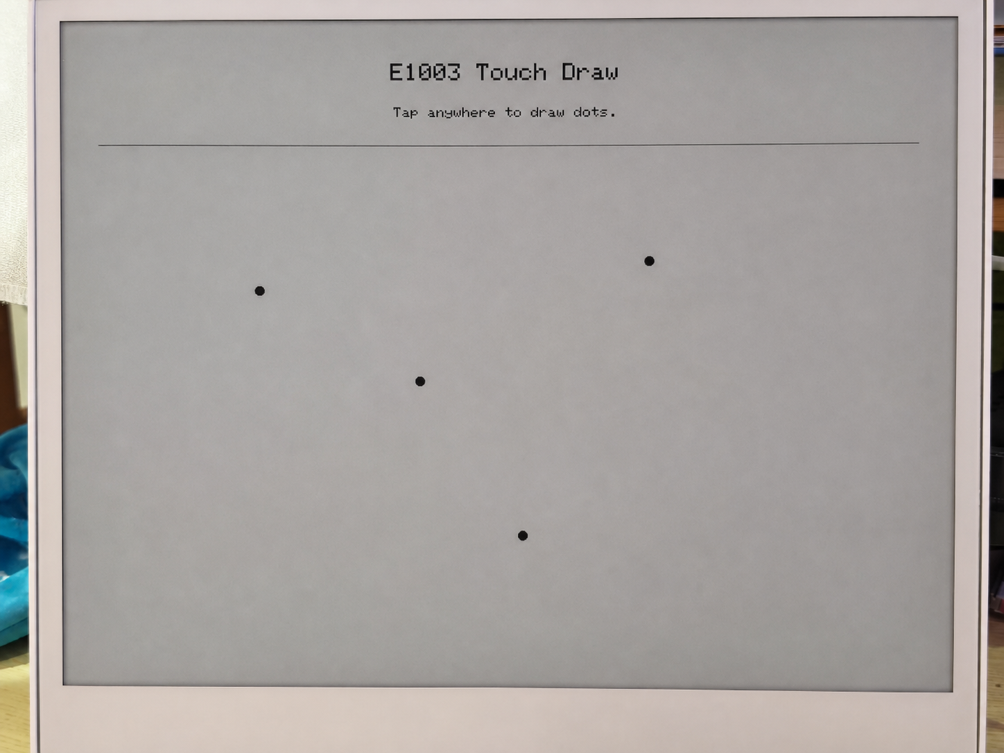
- 绘制启动界面 —— 在 ePaper 上显示 “E1003 Touch Draw” 和提示信息。
触摸轮询循环(loop()):
- 每 30 ms 轮询一次 —— 读取 GT911 状态寄存器以检查是否有新的触摸事件。
- 读取触摸坐标 —— 从 GT911 的点数据寄存器中提取原始 X/Y,然后使用
mapTouchToDisplay()将其映射到显示坐标(该函数会考虑触摸分辨率与显示分辨率之间的差异)。 - 消抖与距离检查 —— 只有在以下情况下才会绘制新的点:
- 距离上次绘制至少已经过去 450 ms,或者
- 触摸点相对于上一次绘制点至少移动了 12 个像素。
- 在 ePaper 上绘制 —— 使用
fillCircle()绘制实心黑点,使用drawCircle()添加灰色光环,然后通过update()将帧缓冲推送到 ePaper 面板。
每次调用 update() 都会触发一次完整的 ePaper 刷新,在 E1003 面板上大约需要 1–2 秒。这是正常现象 —— ePaper 并不是快速刷新的显示屏。消抖逻辑(DRAW_MIN_MS = 450 ms)的设计目的是避免向面板发出过于频繁的刷新请求。
前置条件
在运行此示例前:
- 通过 Arduino Library Manager 安装 Seeed_GFX 库。
- 在 Tools 菜单中将 PSRAM 设置为 OPI PSRAM —— 如果没有 PSRAM,将无法分配显示缓冲区,并且
display_.width()会返回 0。 - 将 Flash Size 设置为 8 MB。
- 选择 XIAO_ESP32S3 开发板。
预期输出
========================================
  E1003_TouchDraw - reTerminal E1003
========================================
[display] PSRAM found: yes, free PSRAM: 8159232 bytes
[display] Ready: 1872 x 1404
[touch] GT9xx found at 0x5D, product: 911
[touch] Touch range: 1872 x 1404, display: 1872 x 1404
[touch] Ready.
点击屏幕后:
[touch] raw=(468,302) screen=(468,302)
[touch] raw=(920,756) screen=(920,756)
[touch] raw=(1400,1100) screen=(1400,1100)
故障排查
Q1:在深度睡眠中仍能看到串口输出——这是否意味着低功耗示例没有生效?
这是正常现象,并不意味着深度睡眠失败。
你看到的串口输出是由载板上的 USB-UART 转换芯片处理的(而不是 ESP32-S3 本身)。该转换芯片直接由 USB 供电,因此无论 ESP32-S3 处于唤醒还是睡眠状态,它都会保持工作。这实际上是一个刻意的设计选择 —— 即使设备进入快速的深度睡眠循环,也能确保你始终可以看到串口输出并上传新固件。
要确认深度睡眠是否真正生效,请检查串口日志:
- 如果你看到
[SLEEP] Entering deep sleep now.后面就没有任何输出,说明设备已经进入深度睡眠。 - 如果你看到
[ERROR] deep sleep did not start!,则说明出现了问题。
Q2:如何在不同场景下正确使用 RTC 示例?
- 首次启动
- 重启 / 重新上电
- 重新校准
场景: 全新开发板或刚刚更换了 CR1220 电池。
你无需更改任何内容 —— 直接按原样上传示例即可。
在全新的开发板上,由于电池从未为时钟供电,PCF8563 内部的 VL(电压低)标志始终为 1。示例在启动时读取到 VL=1 后,会自动将编译时间戳写入 RTC。
确认你的 USER CONFIGURATION 如下所示:
#define USE_COMPILE_TIME     // ← enabled ✓
// #define FORCE_SET_TIME   // ← keep commented ✓
→ 点击 Upload → 完成。
场景: 开发板已经运行过,然后被重启或断电重上电。
你无需做任何操作 —— 只需上电即可。
在主电源关闭时,CR1220 电池会保持 PCF8563 持续计时。启动时,示例读取到 VL=0(电池状态良好),并跳过写入,从而保留已存储的时间。串口输出会立即显示正确时间。
场景: RTC 时间不正确,需要重新校准。
步骤 1 —— 强制覆盖。 取消注释 FORCE_SET_TIME,然后上传:
#define USE_COMPILE_TIME
#define FORCE_SET_TIME      // ← uncomment this line
→ 点击 Upload → 现在时间会被强制设置为编译时间戳。
步骤 2 —— 关闭强制覆盖。 立即再次将其注释掉并重新上传:
#define USE_COMPILE_TIME
// #define FORCE_SET_TIME   // ← comment it back out
→ 点击 Upload → 从现在起,每次重启都会保留已存储的时间。
技术支持与产品讨论
感谢你选择我们的产品!我们将为你提供多种支持,确保你在使用我们产品的过程中尽可能顺畅。我们提供多种沟通渠道,以满足不同的偏好和需求。