ESPHome Cookbook:按钮、蜂鸣器、LED、电池、触摸与低功耗(reTerminal E 系列)
本页假定你已经完成了 reTerminal E 系列的 ESPHome 显示 cookbook(设备已连接 Wi‑Fi、已与 Home Assistant 集成、首个仪表盘已渲染)。关于平台级 YAML 骨架和 Home Assistant 集成步骤,请参阅 使用 ESPHome。关于 RTC、microSD 卡检测和麦克风配置,请参阅 ESPHome Cookbook:RTC、SD 卡与麦克风。电容触摸(GT911)在本页后文介绍,仅适用于 reTerminal E1003。
想要一个现成的 ESPHome 配置,而不是手动拼装每个引脚?打开 reTerminal E-Series Firmware Hub,选择 ESPHome 卡片,挑选你的设备(E1001 / E1002 / E1003 / E1004),然后勾选你需要的板载功能——显示、按钮、电池、传感器、RTC、SD 卡、麦克风、触摸、深度睡眠等。Hub 会生成匹配的 ESPHome YAML,你可以复制或下载到自己的 ESPHome 仪表盘中。
同一个 Hub 也可以直接在浏览器中烧录演示固件(桌面版 Chrome 或 Edge)。关于通用的 ESPHome 工作流程,请参阅 使用 ESPHome。
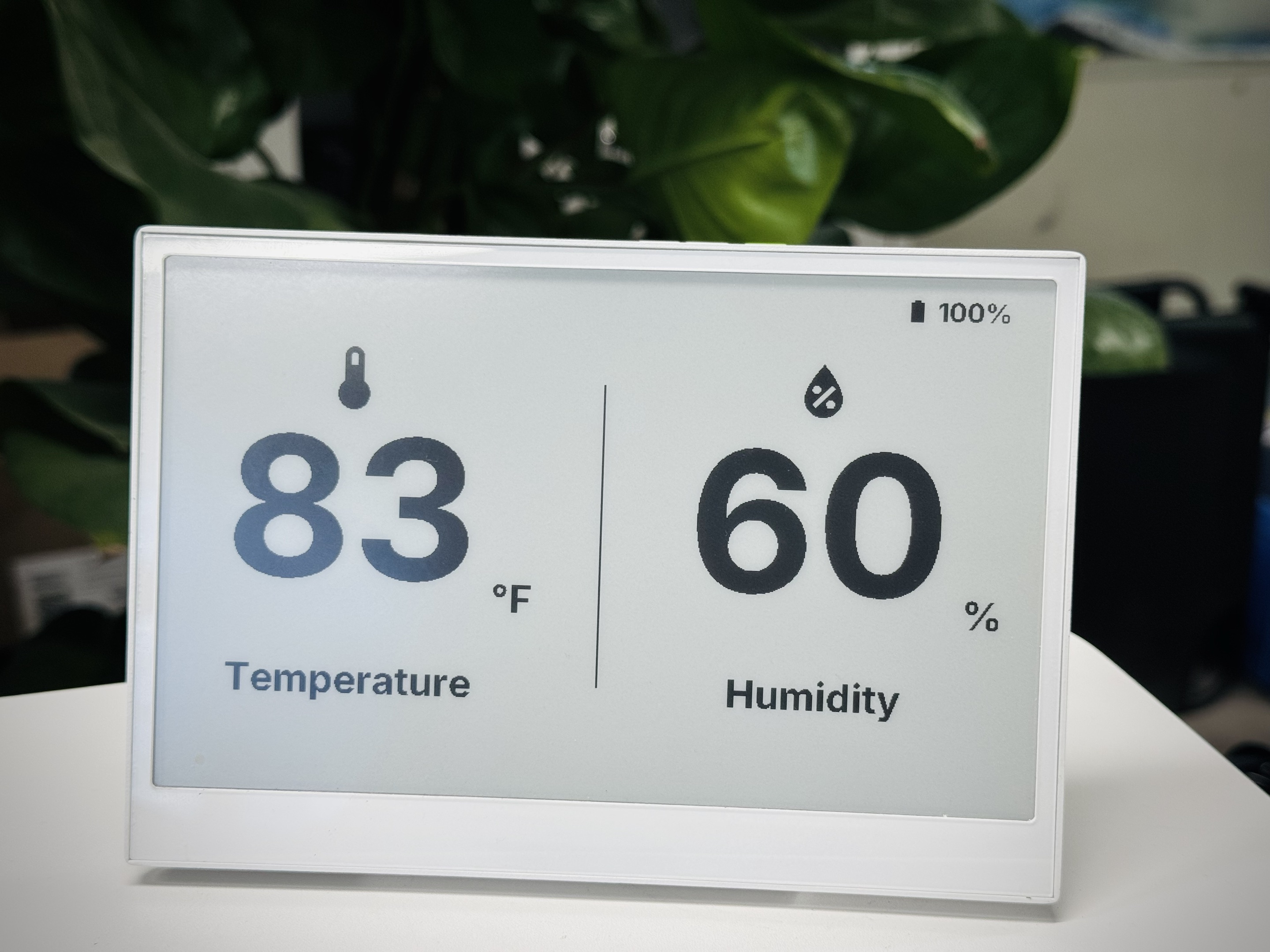
本文介绍如何在 reTerminal E 系列电子墨水屏设备上,通过 ESPHome 配置板载 I/O 和电源相关功能,并在我们 ESPHome 显示 cookbook 中讲解的基础概念之上进一步扩展。如果你刚接触 ESPHome 或 reTerminal E 系列,建议先阅读显示指南,再来使用这些硬件示例。
硬件能力
reTerminal E 系列电子墨水屏包含多种硬件组件,可以通过 ESPHome 在 Home Assistant 中加以利用:
-
三个可编程按钮(GPIO3、GPIO4、GPIO5)
-
蜂鸣器(GPIO45)
-
电池电量监测(GPIO1 读取电压;使能引脚因型号而异)
-
板载 LED(E1001/E1002 为 GPIO6,E1003 为 GPIO16,E1004 为 GPIO48)
-
温湿度传感器(I²C 接口)
-
电容触摸屏(仅 reTerminal E1003 上的 GT911)
下面我们将逐一介绍如何在实际应用中使用这些组件。
本页示例适用于 E1001 / E1002 / E1003 / E1004。对于 E1003 和 E1004 的显示驱动,请使用 ESPHome 2026.7.0 或更高版本。
reTerminal E 系列电子墨水屏硬件组件控制
下面我们将介绍如何在 Home Assistant 中使用 reTerminal E 系列电子墨水屏上的各个硬件组件。
按钮和 LED
本示例演示如何使用 reTerminal E 系列电子墨水屏上的三个按钮来控制功能,并通过板载 LED 提供视觉反馈。
你可以将下面的示例代码复制到你的 Yaml 文件中,放在 captive_portal 代码行之后。
- E1001 / E1002:
GPIO6 - E1003:
GPIO16 - E1004:
GPIO48
请根据你的设备型号,更新上面代码片段中的 output 引脚。
# Button configuration
binary_sensor:
  - platform: gpio
    pin:
      number: GPIO3         # Green button
      mode: INPUT_PULLUP
      inverted: true
    id: button_1
    name: "Button 1"
    on_press:
      then:
        - light.turn_on: onboard_led
        - delay: 500ms
        - light.turn_off: onboard_led

  - platform: gpio
    pin:
      number: GPIO4          # Right white button
      mode: INPUT_PULLUP
      inverted: true
    id: button_2
    name: "Button 2"
    on_press:
      then:
        - light.turn_on: onboard_led
        - delay: 200ms
        - light.turn_off: onboard_led
        - delay: 200ms
        - light.turn_on: onboard_led
        - delay: 200ms
        - light.turn_off: onboard_led

  - platform: gpio
    pin:
      number: GPIO5           # Left white button
      mode: INPUT_PULLUP
      inverted: true
    id: button_3
    name: "Button 3"
    on_press:
      then:
        - light.toggle: onboard_led

# LED configuration
output:
  - platform: gpio
    pin: GPIO6
    id: led_output
    inverted: true

light:
  - platform: binary
    name: "Onboard LED"
    output: led_output
    id: onboard_led
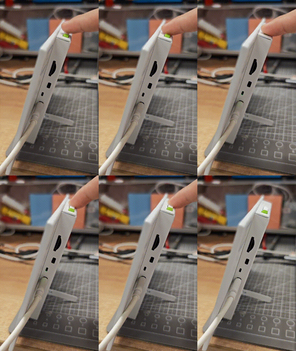
该配置将:
- 将三个按钮全部设置为带上拉电阻的输入
- 配置按钮 1 以短暂闪烁 LED
- 配置按钮 2 以双闪模式闪烁 LED
- 配置按钮 3 以切换 LED 的开/关
- 在 Home Assistant 中将 LED 暴露为可控的灯光实体
蜂鸣器控制
reTerminal E 系列电子墨水屏在 GPIO45 上集成了一个蜂鸣器,可用于提供声音反馈。下面是配置方法:
你可以将下面的示例代码复制到你的 Yaml 文件中,放在 captive_portal 代码行之后。
# This component creates a raw PWM (Pulse Width Modulation) output signal.
# For ESP32, the correct platform is 'ledc', which uses the dedicated LED Control hardware peripheral.
output:
  - platform: ledc   # CORRECTED: 'ledc' is the correct platform for ESP32 PWM.
    pin: GPIO45
    id: buzzer_pwm
    # The frequency determines the pitch of the buzzer's sound. 1000Hz is a mid-range tone.
    frequency: 1000Hz

# Create a light entity to provide a user-friendly way to control the buzzer.
# The 'brightness' of the light will control the PWM duty cycle, which effectively changes the buzzer's volume.
light:
  - platform: monochromatic
    output: buzzer_pwm
    name: "Buzzer"
    id: buzzer
    # Setting transition length to 0s makes the buzzer turn on and off instantly.
    default_transition_length: 0s

# This section defines the physical button that will trigger the buzzer.
binary_sensor:
  - platform: gpio
    pin:
      number: GPIO3            # The GPIO pin connected to the green button.
      mode: INPUT_PULLUP       # Use the internal pull-up resistor.
      inverted: true           # The signal is low when pressed.
    id: button_1
    # 'on_press' defines the sequence of actions to execute when the button is pressed.
    on_press:
      then:
        # First beep: turn on at 50% volume (brightness) for 200 milliseconds.
        - light.turn_on:
            id: buzzer
            brightness: 50%
        - delay: 200ms
        - light.turn_off: buzzer
        # Pause for 100 milliseconds between beeps.
        - delay: 100ms
        # Second beep: turn on at 70% volume for 200 milliseconds.
        - light.turn_on:
            id: buzzer
            brightness: 70%
        - delay: 200ms
        - light.turn_off: buzzer
该配置将:
- 将蜂鸣器设置为 PWM 输出
- 创建一个用于控制蜂鸣器的灯光实体
- 配置按钮 1 在按下时播放一个短促的蜂鸣模式
你可以调整 frequency 参数来改变蜂鸣器的音调。数值越高,音调越尖锐。
电池监测
reTerminal E 系列电子墨水屏可以通过 GPIO1 上的模拟输入监测电池电量。下面是配置方法:
要测量电池电量,必须先打开电池使能输出,然后再读取 GPIO1。请使用与你设备匹配的引脚:
- E1001 / E1002 / E1004:
GPIO21 - E1003:
GPIO40
esphome:
  name: reterminal-e10xx
  friendly_name: reTerminal_E10xx
  on_boot:
    priority: 600
    then:
      - output.turn_on: bsp_battery_enable

esp32:
  board: esp32-s3-devkitc-1
  framework:
    type: arduino

# Enable logging
logger:

# Enable Home Assistant API
api:
  encryption:
    key: "REPLACE_WITH_YOUR_API_KEY"

ota:
  - platform: esphome
    password: "REPLACE_WITH_YOUR_OTA_PASSWORD"

wifi:
  ssid: !secret wifi_ssid
  password: !secret wifi_password

  # Enable fallback hotspot (captive portal) in case wifi connection fails
  ap:
    ssid: "Reterminal-E10Xx"
    password: "ChangeMe123"

captive_portal:

output:
  - platform: gpio
    pin: GPIO21
    id: bsp_battery_enable

sensor:
  - platform: adc
    pin: GPIO1
    name: "Battery Voltage"
    id: battery_voltage
    update_interval: 60s
    attenuation: 12db
    filters:
      - multiply: 2.0  # Voltage divider compensation

  - platform: template
    name: "Battery Level"
    id: battery_level
    unit_of_measurement: "%"
    icon: "mdi:battery"
    device_class: battery
    state_class: measurement
    lambda: 'return id(battery_voltage).state;'
    update_interval: 10s
    filters:
      - calibrate_linear:
          - 4.15 -> 100.0
          - 3.96 -> 90.0
          - 3.91 -> 80.0
          - 3.85 -> 70.0
          - 3.80 -> 60.0
          - 3.75 -> 50.0
          - 3.68 -> 40.0
          - 3.58 -> 30.0
          - 3.49 -> 20.0
          - 3.41 -> 10.0
          - 3.30 -> 5.0
          - 3.27 -> 0.0
      - clamp:
          min_value: 0
          max_value: 100
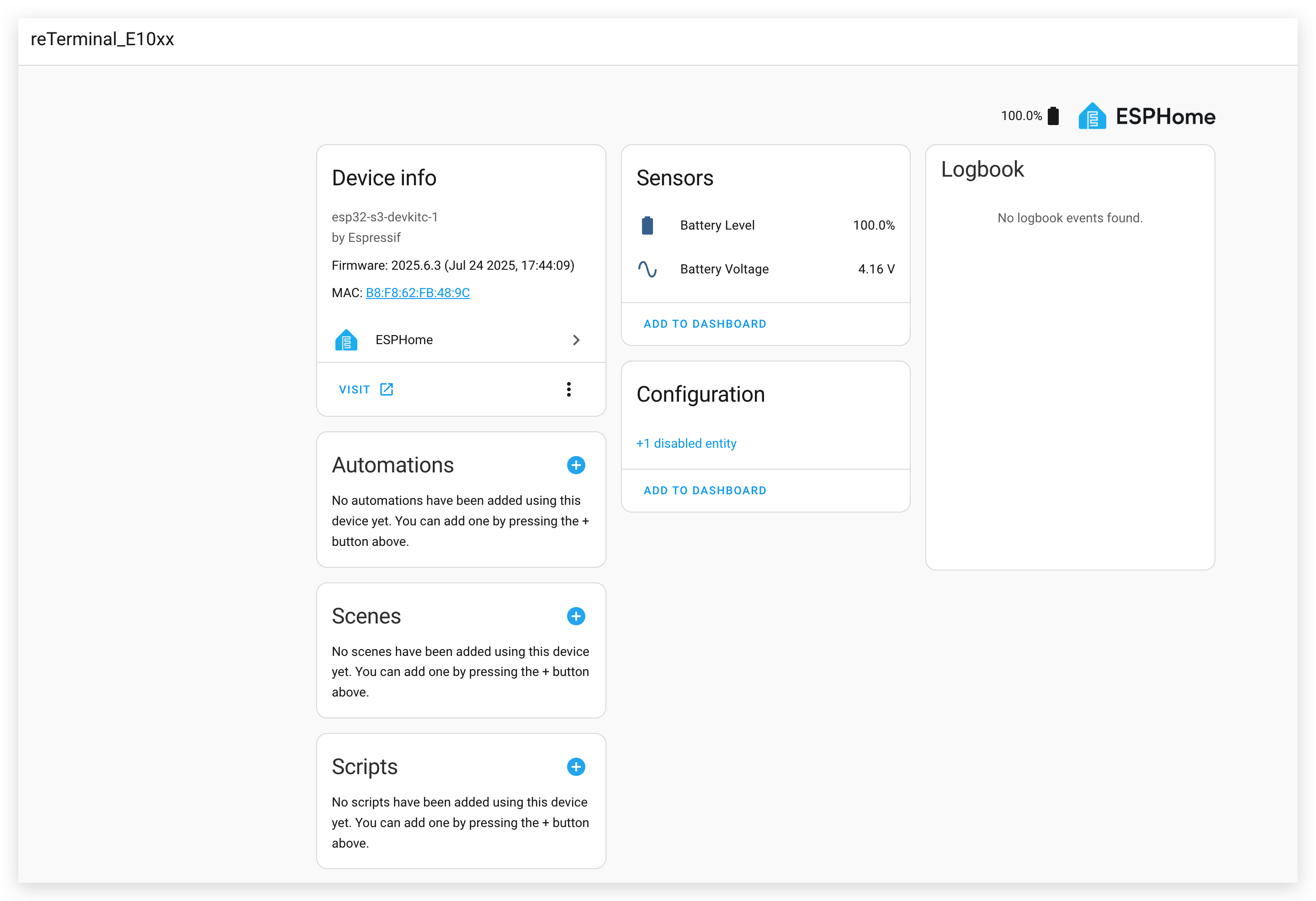
该配置将:
- 通过 ADC 读取电池电压
- 使用校准曲线将电压转换为电池电量百分比
- 使原始电压和百分比都可在 Home Assistant 中使用
演示 2. 将 Home Assistant 仪表板作为截图显示
本示例演示如何捕获 Home Assistant 仪表板的截图,并将其显示在 reTerminal E 系列上。
安装 Puppet 插件
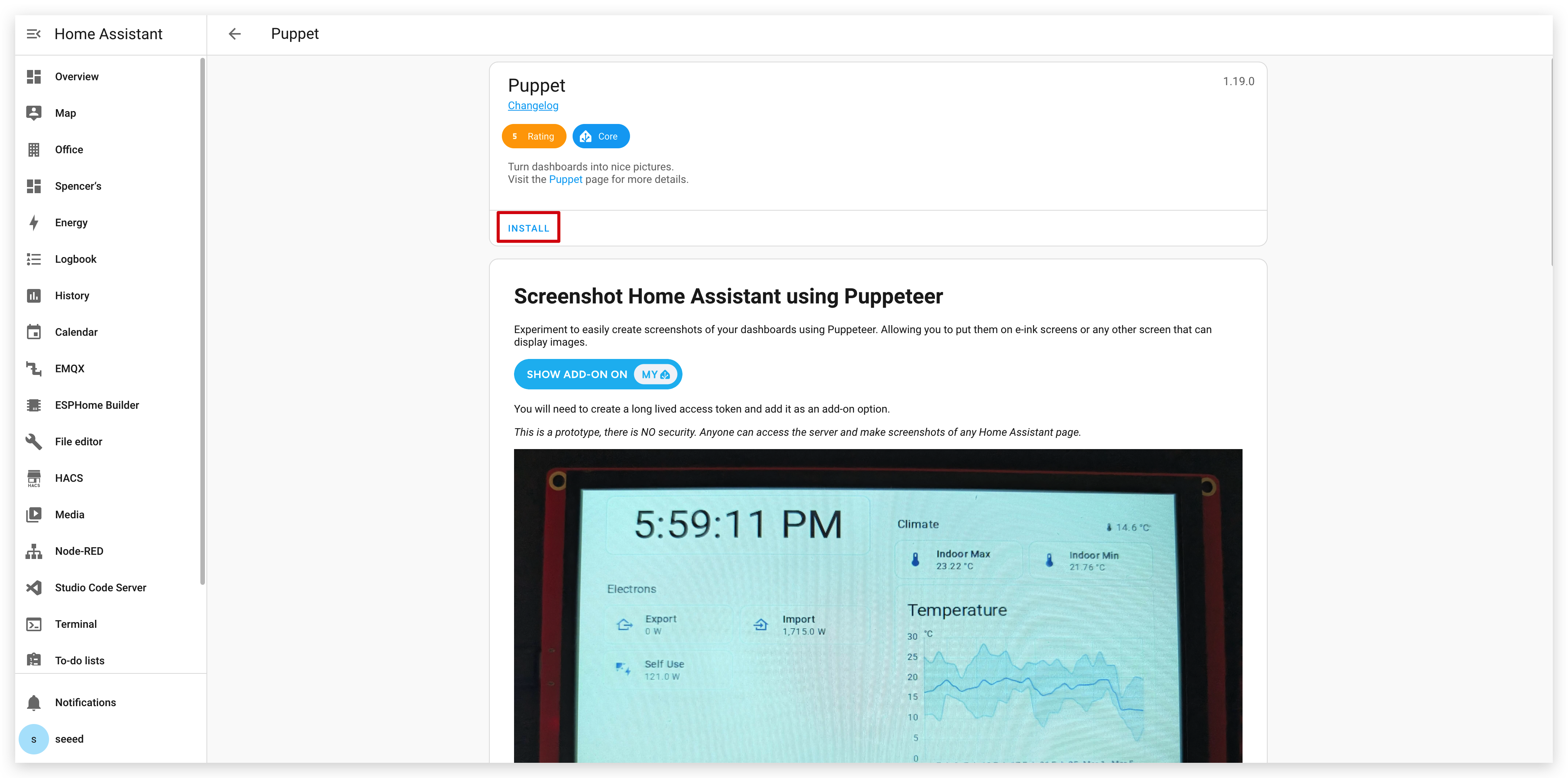
步骤 1. 首先,你需要安装 Puppet 插件。点击下面的按钮,它会直接带你进入 Home Assistant 实例中的插件安装页面:
步骤 2. 在插件页面,点击 "INSTALL" 按钮并等待安装完成。
创建访问令牌
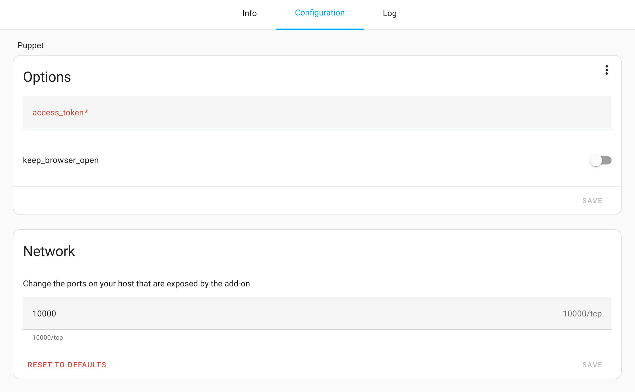
步骤 3. 安装完成后,进入 Puppet 插件的 Configuration 页面。如你所见,这里我们需要输入令牌。你需要为此插件创建一个访问令牌。
步骤 4. 在 Home Assistant 中点击左下角的用户名进入你的个人资料页面,然后在页面底部选择 "Long-Lived Access Tokens"。
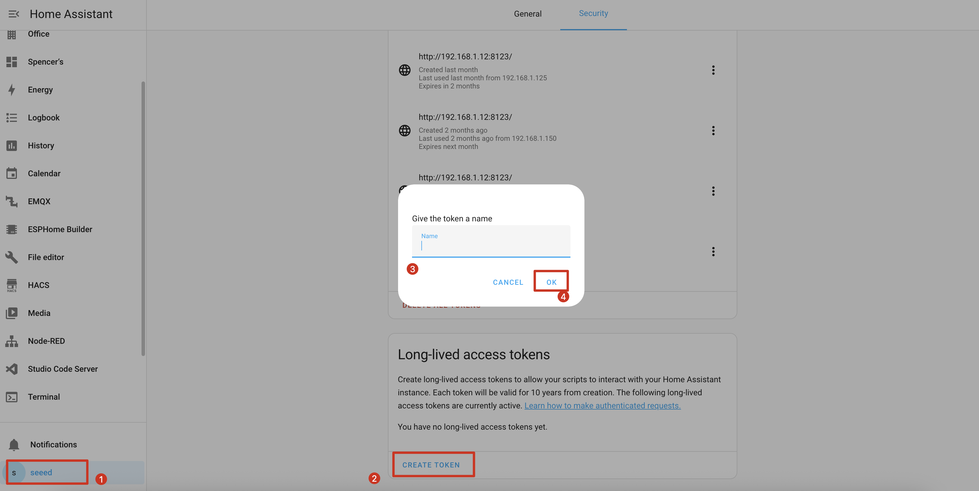
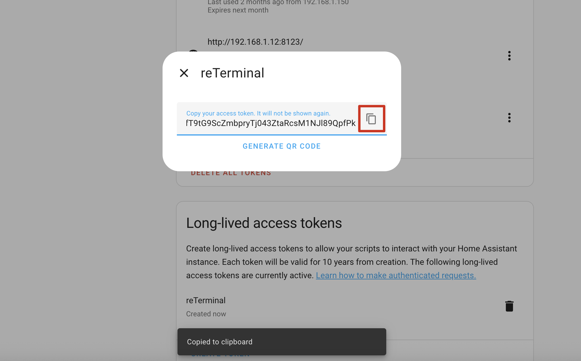
步骤 5. 创建一个新的令牌,并使用类似 "Puppet Screenshot" 这样的描述性名称,然后复制生成的令牌。
步骤 6. 返回 Puppet 插件的配置页面,并将令牌粘贴到 "Long-Lived Access Token" 字段中。
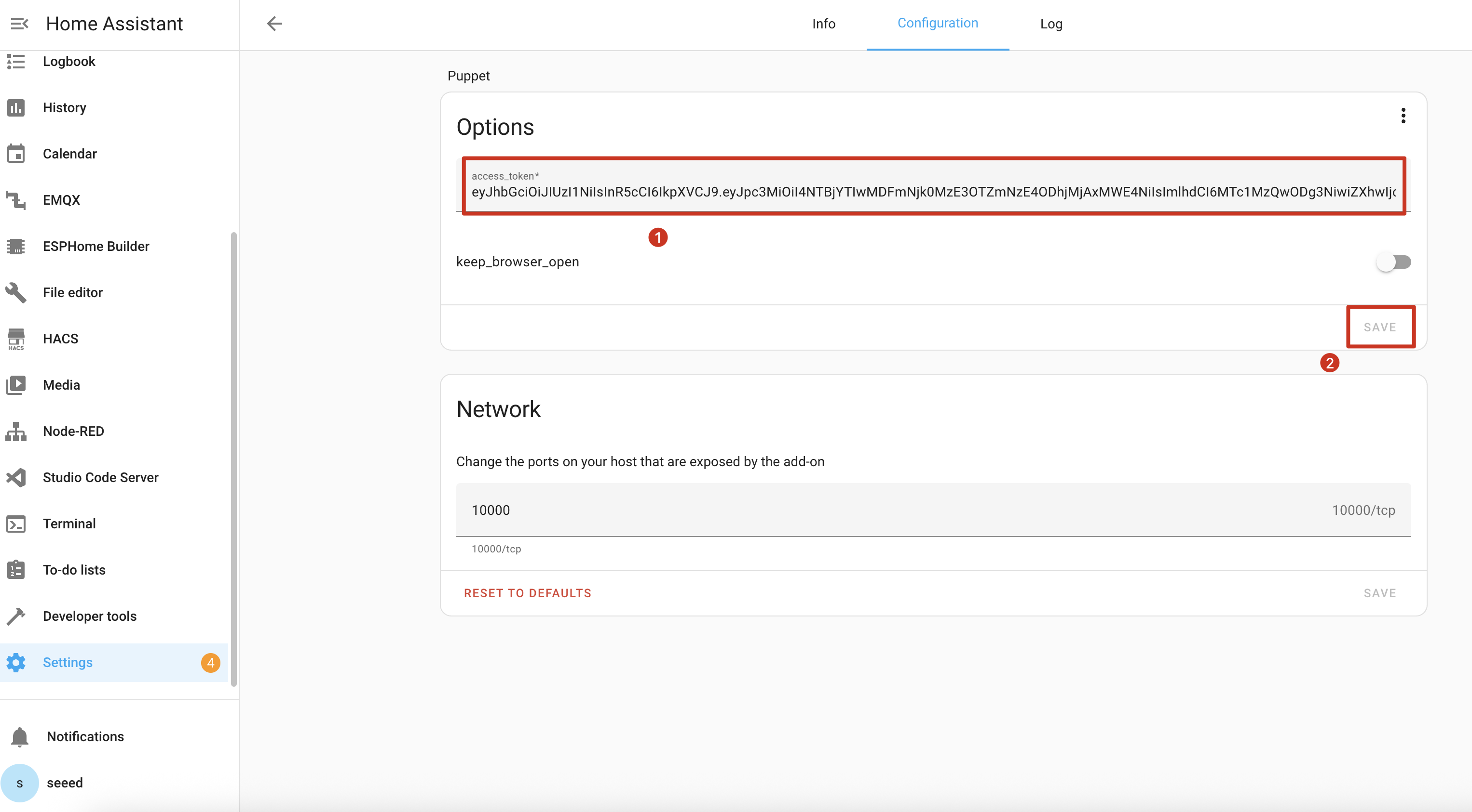
步骤 7. 保存配置并重启 Puppet 插件。

了解截图 API
Puppet 插件在端口 10000 上启动了一个服务器,用于生成任意 Home Assistant 页面截图。使用方式如下:
基本截图 URL 格式
http://homeassistant.local:10000/lovelace/0?viewport=800x480
此 URL 将以 800x480 分辨率捕获你的默认仪表板截图(非常适合 reTerminal E 系列)。
电子纸优化
对于电子纸显示屏,添加 eink 参数以减少色彩调色板:
http://homeassistant.local:10000/lovelace/0?viewport=800x480&eink=2
值 2 表示 2 色(黑白)调色板。
反转颜色
添加 invert 参数以反转黑白:
http://homeassistant.local:10000/lovelace/0?viewport=800x480&eink=2&invert
捕获不同页面
你可以通过更改 URL 路径来捕获任意 Home Assistant 页面:
http://homeassistant.local:10000/todo?viewport=800x480&eink=2&invert
在浏览器中输入你的截图 URL 进行测试。你应该会看到所选 Home Assistant 页面的截图。

ESPHome 配置
步骤 11. 将以下代码添加到 ESPHome 配置中 captive_portal 部分之后:
- 适用于 E1001
- 适用于 E1002
- 适用于 E1003
- 适用于 E1004
……
psram:
  mode: octal
  speed: 80MHz

……

captive_portal:

spi:
  clk_pin: GPIO7
  mosi_pin: GPIO9

http_request:
  verify_ssl: false
  timeout: 20s
  watchdog_timeout: 25s

online_image:
  - id: dashboard_image
    format: PNG
    type: GRAYSCALE
    buffer_size: 65536
    url: http://homeassistant.local:10000/lovelace/0?viewport=800x480&eink=2&invert
    update_interval: 1min
    on_download_finished:
      - component.update: epaper_display

display:
  - platform: waveshare_epaper
    id: epaper_display
    model: 7.50inv2 # You can use 7.50inv2alt when you draw complex info and it display not good.
    cs_pin: GPIO10
    dc_pin: GPIO11
    reset_pin:
      number: GPIO12
      inverted: false
    busy_pin:
      number: GPIO13
      inverted: true
    update_interval: 300s
    lambda: |-
      it.image(0, 0, id(dashboard_image));
……
psram:
  mode: octal
  speed: 80MHz

……

captive_portal:

spi:
  clk_pin: GPIO7
  mosi_pin: GPIO9

http_request:
  verify_ssl: false
  timeout: 20s
  watchdog_timeout: 25s

online_image:
  - id: dashboard_image
    format: PNG
    type: RGB565
    buffer_size: 65536
    url: http://192.168.1.12:10000/lovelace/0?viewport=800x480
    update_interval: 1min
    on_download_finished:
      - component.update: epaper_display

display:
  - platform: epaper_spi
    id: epaper_display
    model: Seeed-reTerminal-E1002
    update_interval: never
    lambda: |-
      it.image(0, 0, id(dashboard_image));
请将 ESPHome 版本更新到 2026.7.0 或更高版本。如果你希望捕获的内容更接近原生 1872×1404 面板,请调整 viewport 大小。
……
psram:
  mode: octal
  speed: 80MHz

……

captive_portal:

spi:
  id: epaper_spi_bus
  clk_pin: GPIO7
  mosi_pin: GPIO9
  miso_pin: GPIO8

http_request:
  verify_ssl: false
  timeout: 20s
  watchdog_timeout: 25s

online_image:
  - id: dashboard_image
    format: PNG
    type: GRAYSCALE
    buffer_size: 65536
    url: http://homeassistant.local:10000/lovelace/0?viewport=800x480&eink=2&invert
    update_interval: 1min
    on_download_finished:
      - component.update: epaper_display

display:
  - platform: it8951
    id: epaper_display
    spi_id: epaper_spi_bus
    model: seeed-reterminal-e1003
    update_interval: never
    full_update_every: 30
    grayscale: true
    dithering: true
    update_mode: GC16
    transform:
      mirror_x: true
      mirror_y: false
    lambda: |-
      it.image(0, 0, id(dashboard_image));
请将 ESPHome 版本更新到 2026.7.0 或更高版本。如果你希望捕获的内容更接近原生 1200×1600 面板,请调整 viewport 大小。
……
psram:
  mode: octal
  speed: 80MHz

……

captive_portal:

spi:
  clk_pin: GPIO7
  mosi_pin: GPIO9

http_request:
  verify_ssl: false
  timeout: 20s
  watchdog_timeout: 25s

online_image:
  - id: dashboard_image
    format: PNG
    type: RGB565
    buffer_size: 65536
    url: http://homeassistant.local:10000/lovelace/0?viewport=800x480
    update_interval: 1min
    on_download_finished:
      - component.update: epaper_display

display:
  - platform: epaper_spi
    id: epaper_display
    model: seeed-reterminal-e1004
    update_interval: never
    lambda: |-
      it.image(0, 0, id(dashboard_image));
如果在你的网络中本地域名解析不起作用,请将 homeassistant.local 替换为 Home Assistant 实际的 IP 地址。
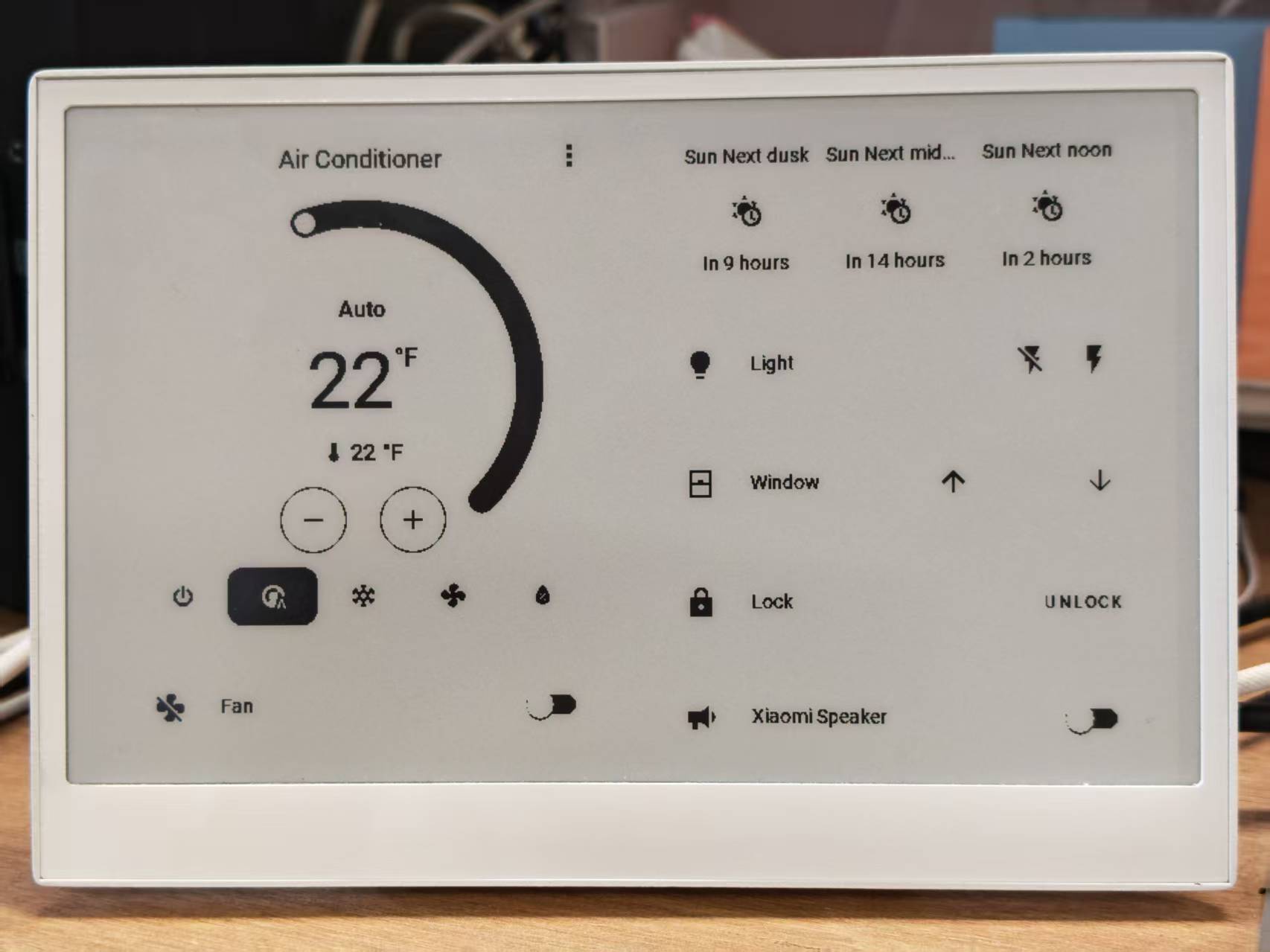
当你的配置成功上传并运行后,reTerminal E 系列电子纸显示屏将显示 Home Assistant 仪表板的截图:
- 适用于 E1001
- 适用于 E1002

演示 3:深度睡眠模式
如果你开始使用深度睡眠程序,我们建议你最好配合右侧的白色按键使用,并将右侧白色按键设置为唤醒睡眠按键。这样,当你想要更新程序时,就不会遇到设备处于睡眠状态而无法通过串口上传程序的尴尬情况。
本示例演示如何使用深度睡眠模式大幅降低功耗,使 reTerminal E 系列电子纸显示屏适用于电池供电的应用场景。
你可以通过复制下面的代码,并将其粘贴到 Yaml 文件中 captive_portal 代码行之后来使用此示例。
- 适用于 E1001
- 适用于 E1002
- 适用于 E1003
- 适用于 E1004
globals:
  - id: sleep_counter
    type: int
    restore_value: yes  # Use RTC storage to maintain counter during sleep
    initial_value: '0'

# Deep sleep configuration
deep_sleep:
  id: deep_sleep_1
  run_duration: 30s  # Device remains awake for 30 seconds
  sleep_duration: 5min  # Then sleeps for 5 minutes
  # Optional: Use a button to wake from sleep
  wakeup_pin: GPIO4
  wakeup_pin_mode: INVERT_WAKEUP

interval:
  - interval: 29s  # Schedule sleep just before run_duration ends
    then:
      - logger.log: "Entering deep sleep now..."

font:
  - file: "gfonts://Inter@700"
    id: font1
    size: 24

spi:
  clk_pin: GPIO7
  mosi_pin: GPIO9

display:
  - platform: waveshare_epaper
    id: epaper_display
    model: 7.50inv2
    cs_pin: GPIO10
    dc_pin: GPIO11
    reset_pin:
      number: GPIO12
      inverted: false
    busy_pin:
      number: GPIO13
      inverted: true
    update_interval: 5min
    lambda: |-
      id(sleep_counter) += 1;
      ESP_LOGD("main", "Wakeup count: %d", id(sleep_counter));
      it.printf(100, 100, id(font1), "Wakeup count: %d", id(sleep_counter));
globals:
  - id: sleep_counter
    type: int
    restore_value: yes  # Use RTC storage to maintain counter during sleep
    initial_value: '0'

# Deep sleep configuration
deep_sleep:
  id: deep_sleep_1
  run_duration: 30s  # Device remains awake for 30 seconds
  sleep_duration: 5min  # Then sleeps for 5 minutes
  # Optional: Use a button to wake from sleep
  wakeup_pin: GPIO4
  wakeup_pin_mode: INVERT_WAKEUP

interval:
  - interval: 29s  # Schedule sleep just before run_duration ends
    then:
      - logger.log: "Entering deep sleep now..."

font:
  - file: "gfonts://Inter@700"
    id: font1
    size: 24

spi:
  clk_pin: GPIO7
  mosi_pin: GPIO9

display:
  - platform: epaper_spi
    id: epaper_display
    model: Seeed-reTerminal-E1002
    update_interval: 5min
    lambda: |-
      const auto BLACK   = Color(0,   0,   0,   0);
      id(sleep_counter) += 1;
      ESP_LOGD("main", "Wakeup count: %d", id(sleep_counter));
      it.printf(100, 100, id(font1), BLACK, "Wakeup count: %d", id(sleep_counter));
请将你的 ESPHome 版本更新到 2026.7.0 或更高。本示例通过 GPIO3 上的右侧绿色按钮唤醒。
globals:
  - id: sleep_counter
    type: int
    restore_value: yes  # Use RTC storage to maintain counter during sleep
    initial_value: '0'

# Deep sleep configuration
deep_sleep:
  id: deep_sleep_1
  run_duration: 30s  # Device remains awake for 30 seconds
  sleep_duration: 5min  # Then sleeps for 5 minutes
  esp32_ext1_wakeup:
    pins:
      - number: GPIO3
        allow_other_uses: true
        mode: INPUT_PULLUP
    mode: ANY_LOW

interval:
  - interval: 29s  # Schedule sleep just before run_duration ends
    then:
      - logger.log: "Entering deep sleep now..."

font:
  - file: "gfonts://Inter@700"
    id: font1
    size: 24

psram:
  mode: octal

spi:
  id: epaper_spi_bus
  clk_pin: GPIO7
  mosi_pin: GPIO9
  miso_pin: GPIO8

display:
  - platform: it8951
    id: epaper_display
    spi_id: epaper_spi_bus
    model: seeed-reterminal-e1003
    update_interval: 5min
    full_update_every: 30
    grayscale: true
    dithering: true
    update_mode: GC16
    transform:
      mirror_x: true
      mirror_y: false
    lambda: |-
      id(sleep_counter) += 1;
      ESP_LOGD("main", "Wakeup count: %d", id(sleep_counter));
      it.printf(100, 100, id(font1), Color::BLACK, "Wakeup count: %d", id(sleep_counter));
请将你的 ESPHome 版本更新到 2026.7.0 或更高。本示例通过 GPIO4 上的前方向按钮唤醒。
globals:
  - id: sleep_counter
    type: int
    restore_value: yes  # Use RTC storage to maintain counter during sleep
    initial_value: '0'

# Deep sleep configuration
deep_sleep:
  id: deep_sleep_1
  run_duration: 30s  # Device remains awake for 30 seconds
  sleep_duration: 5min  # Then sleeps for 5 minutes
  esp32_ext1_wakeup:
    pins:
      - number: GPIO4
        allow_other_uses: true
        mode: INPUT_PULLUP
    mode: ANY_LOW

interval:
  - interval: 29s  # Schedule sleep just before run_duration ends
    then:
      - logger.log: "Entering deep sleep now..."

font:
  - file: "gfonts://Inter@700"
    id: font1
    size: 24

psram:
  mode: octal

spi:
  clk_pin: GPIO7
  mosi_pin: GPIO9

display:
  - platform: epaper_spi
    id: epaper_display
    model: seeed-reterminal-e1004
    update_interval: 5min
    lambda: |-
      const auto BLACK   = Color(0,   0,   0,   0);
      id(sleep_counter) += 1;
      ESP_LOGD("main", "Wakeup count: %d", id(sleep_counter));
      it.printf(100, 100, id(font1), BLACK, "Wakeup count: %d", id(sleep_counter));
此配置:
- 创建一个在睡眠周期之间保持的计数器
- 将设备配置为唤醒 30 秒,然后睡眠 3 分钟
- 使用当前唤醒次数更新显示屏
- 可选地配置一个按钮来唤醒设备
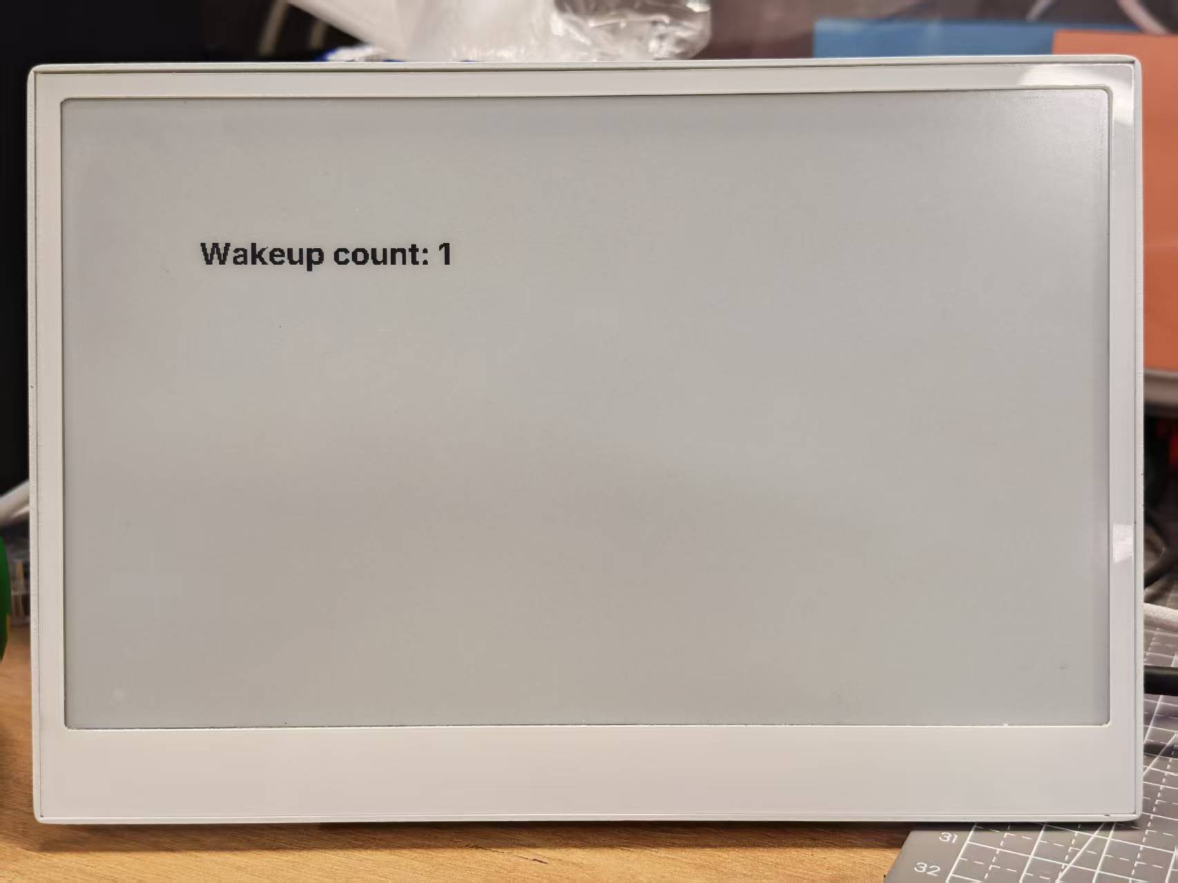
运行时,你会看到每次设备从睡眠中唤醒时计数器都会递增:
演示 4:综合示例
为了更好地理解,我们强烈建议你先运行上面的基础示例,再尝试这个综合示例。
这个高级示例将多个功能组合成 reTerminal E 系列的完整仪表盘解决方案。它演示了:
- 天气和室内环境显示
- 带图标的电池监控
- 时间和日期显示
- 使用按钮进行页面切换
- 电池监控
点击此处查看完整代码
- 适用于 E1001
- 适用于 E1002
- 适用于 E1003
- 适用于 E1004
esphome:
  name: reterminal_e1001
  friendly_name: reTerminal_E1001
  on_boot:
    priority: 600
    then:
      - output.turn_on: bsp_sd_enable
      - output.turn_on: bsp_battery_enable
      - delay: 200ms
      - component.update: battery_voltage
      - component.update: battery_level


esp32:
  board: esp32-s3-devkitc-1
  framework:
    type: arduino

# Enable logging
logger:

# Enable Home Assistant API
api:
  encryption:
    key: "REPLACE_WITH_YOUR_API_KEY"

ota:
  - platform: esphome
    password: "REPLACE_WITH_YOUR_OTA_PASSWORD"

wifi:
  ssid: !secret wifi_ssid
  password: !secret wifi_password

  # Enable fallback hotspot (captive portal) in case wifi connection fails
  ap:
    ssid: "reTerminal-E1001"
    password: "ChangeMe123"

captive_portal:

# Deep-sleep, wake by GPIO4
deep_sleep:
  id: deep_sleep_1
  run_duration: 1min
  sleep_duration: 60min
  wakeup_pin: GPIO4          # Right white button
  wakeup_pin_mode: INVERT_WAKEUP

# SPI / I²C
spi:
  clk_pin: GPIO7
  mosi_pin: GPIO9
i2c:
  scl: GPIO20
  sda: GPIO19

# Fonts
font:
  - file: "gfonts://Inter@700"
    id: small_font
    size: 24
  - file: "gfonts://Inter@700"
    id: mid_font
    size: 36
  - file: "gfonts://Inter@700"
    id: big_font
    size: 180
  - file: "gfonts://Inter@700"
    id: time_font
    size: 96      # for the big time display
  - file: 'fonts/materialdesignicons-webfont.ttf'
    id: font_mdi_large
    size: 70
    glyphs:
      - "\U000F050F"  # thermometer
      - "\U000F058E"  # humidity
  - file: 'fonts/materialdesignicons-webfont.ttf'
    id: font_bat_icon
    size: 24
    glyphs:
      - "\U000F007A"  # mdi-battery-10
      - "\U000F007B"  # mdi-battery-20
      - "\U000F007C"  # mdi-battery-30
      - "\U000F007D"  # mdi-battery-40
      - "\U000F007E"  # mdi-battery-50
      - "\U000F007F"  # mdi-battery-60
      - "\U000F0080"  # mdi-battery-70
      - "\U000F0081"  # mdi-battery-80
      - "\U000F0082"  # mdi-battery-90
      - "\U000F0079"  # mdi-battery

globals:
  - id: page_index
    type: int
    restore_value: true
    initial_value: '0'
  - id: battery_glyph
    type: std::string
    restore_value: no
    initial_value: "\"\\U000F0079\""   # default full battery

sensor:
  - platform: sht4x
    temperature:
      name: "Temperature"
      id: temp_sensor
    humidity:
      name: "Relative Humidity"
      id: hum_sensor
  - platform: adc
    pin: GPIO1
    name: "Battery Voltage"
    id: battery_voltage
    update_interval: 60s
    attenuation: 12db
    filters:
      - multiply: 2.0
  - platform: template
    name: "Battery Level"
    id: battery_level
    unit_of_measurement: "%"
    icon: "mdi:battery"
    device_class: battery
    state_class: measurement
    lambda: 'return id(battery_voltage).state;'
    update_interval: 60s
    on_value:
      then:
        - lambda: |-
            int pct = int(x);
            if (pct <= 10)      id(battery_glyph) = "\U000F007A";
            else if (pct <= 20) id(battery_glyph) = "\U000F007B";
            else if (pct <= 30) id(battery_glyph) = "\U000F007C";
            else if (pct <= 40) id(battery_glyph) = "\U000F007D";
            else if (pct <= 50) id(battery_glyph) = "\U000F007E";
            else if (pct <= 60) id(battery_glyph) = "\U000F007F";
            else if (pct <= 70) id(battery_glyph) = "\U000F0080";
            else if (pct <= 80) id(battery_glyph) = "\U000F0081";
            else if (pct <= 90) id(battery_glyph) = "\U000F0082";
            else                id(battery_glyph) = "\U000F0079";
    filters:
      - calibrate_linear:
          - 4.15 -> 100.0
          - 3.96 -> 90.0
          - 3.91 -> 80.0
          - 3.85 -> 70.0
          - 3.80 -> 60.0
          - 3.75 -> 50.0
          - 3.68 -> 40.0
          - 3.58 -> 30.0
          - 3.49 -> 20.0
          - 3.41 -> 10.0
          - 3.30 -> 5.0
          - 3.27 -> 0.0
      - clamp:
          min_value: 0
          max_value: 100

output:
  - platform: gpio
    pin: GPIO6
    id: bsp_led
    inverted: true
  - platform: gpio
    pin: GPIO16
    id: bsp_sd_enable
  - platform: gpio
    pin: GPIO21
    id: bsp_battery_enable

# Onboard LED
light:
  - platform: binary
    name: "Onboard LED"
    output: bsp_led
    id: onboard_led

binary_sensor:
  - platform: gpio    # Next page
    pin:
      number: GPIO3
      mode: INPUT_PULLUP
      inverted: true
    id: key1
    name: "Key1"
    on_press:
      then:
        - lambda: |-
            id(page_index) = (id(page_index) + 1) % 2;
            id(epaper_display).update();

  - platform: gpio     # Prev page
    pin:
      number: GPIO5
      mode: INPUT_PULLUP
      inverted: true
    id: key2
    name: "Key2"
    on_press:
      then:
        - lambda: |-
            id(page_index) = (id(page_index) - 1 + 2) % 2;
            id(epaper_display).update();

  # - platform: gpio
  #   pin:
  #     number: GPIO4
  #     mode: INPUT_PULLUP
  #     inverted: true
  #   id: key2
  #   name: "Key2"
  #   on_press:
  #     then:
  #       - lambda: |-
  #           id(page_index) = (id(page_index) - 1 + 3) % 3;
  #           id(epaper_display).update();

# Home Assistant time
time:
  - platform: homeassistant
    id: ha_time

# e-paper
display:
  - platform: waveshare_epaper
    id: epaper_display
    model: 7.50inv2
    cs_pin: GPIO10
    dc_pin: GPIO11
    reset_pin:
      number: GPIO12
      inverted: false
    busy_pin:
      number: GPIO13
      inverted: true
    update_interval: never
    lambda: |-
      // ----------  PAGE 0  ----------
      if (id(page_index) == 0) {
        const int scr_w = 800;
        const int scr_h = 480;

        // Battery in upper-right corner
        it.printf(670, 13, id(font_bat_icon), "%s", id(battery_glyph).c_str());
        it.printf(700, 10, id(small_font), "%.0f%%", id(battery_level).state);

        //line
        it.filled_rectangle(400, 100, 2, 280);

        // Convert °C to °F
        float temp_f = id(temp_sensor).state * 9.0 / 5.0 + 32.0;

        // ---------------------------------------------------------
        // Horizontal split: two 400 px columns
        const int col_w = scr_w / 2;

        const int icon_y   = 100;   // Icon baseline
        const int value_y  = 220;   // Number baseline
        const int unit_y   = 300;   // Unit baseline
        const int label_y  = 380;   // Text label baseline

        const int icon_size = 70;   // icon font size
        const int val_size  = 120;  // number font size
        const int unit_size = 44;   // unit font size
        const int label_size= 36;   // label font size

        // --- Left column : Temperature -----------------------------
        const int left_mid = col_w / 2 - 30;   // 200 px

        // Icon
        it.printf(left_mid, icon_y, id(font_mdi_large), TextAlign::CENTER, "\U000F050F");
        // Value
        it.printf(left_mid, value_y, id(big_font), TextAlign::CENTER, "%.0f", temp_f);
        // Unit
        it.printf(left_mid + 150, unit_y, id(mid_font), TextAlign::CENTER, "°F");
        // Label
        it.printf(left_mid, label_y, id(mid_font), TextAlign::CENTER, "Temperature");

        // --- Right column : Humidity -------------------------------
        const int right_mid = col_w + col_w / 2;   // 600 px

        // Icon
        it.printf(right_mid, icon_y, id(font_mdi_large), TextAlign::CENTER, "\U000F058E");
        // Value
        it.printf(right_mid, value_y, id(big_font), TextAlign::CENTER, "%.0f", id(hum_sensor).state);
        // Unit
        it.printf(right_mid + 150, unit_y, id(mid_font), TextAlign::CENTER, "%%");
        // Label
        it.printf(right_mid, label_y, id(mid_font), TextAlign::CENTER, "Humidity");
      }
      // ----------  PAGE 1  ----------
      else{
        // Battery top-right
        it.printf(670, 13, id(font_bat_icon), "%s", id(battery_glyph).c_str());
        it.printf(700, 10, id(small_font), "%.0f%%", id(battery_level).state);

        auto now = id(ha_time).now();
        struct tm timeinfo = now.to_c_tm();

        // centering time HH:MM
        char timeStr[6];
        strftime(timeStr, sizeof(timeStr), "%H:%M", &timeinfo);
        it.printf(400, 180, id(time_font), TextAlign::CENTER, timeStr);

        // Date: Day of week
        const char *weekday[] = {"Sun","Mon","Tue","Wed","Thu","Fri","Sat"};
        const char *wday = weekday[timeinfo.tm_wday];

        // Date: month - day
        char dateStr[12];
        strftime(dateStr, sizeof(dateStr), "%b %d", &timeinfo);  // e.g. Jun 15

        // Day of the week + date below the time
        it.printf(400, 280, id(mid_font), TextAlign::CENTER, "%s, %s", wday, dateStr);
      }
esphome:
  name: reterminal_e1002
  friendly_name: reTerminal_E1002
  on_boot:
    priority: 600
    then:
      - output.turn_on: bsp_sd_enable
      - output.turn_on: bsp_battery_enable
      - delay: 200ms
      - component.update: battery_voltage
      - component.update: battery_level


esp32:
  board: esp32-s3-devkitc-1
  framework:
    type: arduino

# Enable logging
logger:

# Enable Home Assistant API
api:
  encryption:
    key: "REPLACE_WITH_YOUR_API_KEY"

ota:
  - platform: esphome
    password: "REPLACE_WITH_YOUR_OTA_PASSWORD"

wifi:
  ssid: !secret wifi_ssid
  password: !secret wifi_password

  # Enable fallback hotspot (captive portal) in case wifi connection fails
  ap:
    ssid: "reTerminal-E1002"
    password: "ChangeMe123"

captive_portal:

# Deep-sleep, wake by GPIO4
deep_sleep:
  id: deep_sleep_1
  run_duration: 1min
  sleep_duration: 60min
  wakeup_pin: GPIO4          # Right white button
  wakeup_pin_mode: INVERT_WAKEUP

# SPI / I²C
spi:
  clk_pin: GPIO7
  mosi_pin: GPIO9
i2c:
  scl: GPIO20
  sda: GPIO19

# Fonts
font:
  - file: "gfonts://Inter@700"
    id: small_font
    size: 24
  - file: "gfonts://Inter@700"
    id: mid_font
    size: 36
  - file: "gfonts://Inter@700"
    id: big_font
    size: 180
  - file: "gfonts://Inter@700"
    id: time_font
    size: 96      # for the big time display
  - file: 'fonts/materialdesignicons-webfont.ttf'
    id: font_mdi_large
    size: 70
    glyphs:
      - "\U000F050F"  # thermometer
      - "\U000F058E"  # humidity
  - file: 'fonts/materialdesignicons-webfont.ttf'
    id: font_bat_icon
    size: 24
    glyphs:
      - "\U000F007A"  # mdi-battery-10
      - "\U000F007B"  # mdi-battery-20
      - "\U000F007C"  # mdi-battery-30
      - "\U000F007D"  # mdi-battery-40
      - "\U000F007E"  # mdi-battery-50
      - "\U000F007F"  # mdi-battery-60
      - "\U000F0080"  # mdi-battery-70
      - "\U000F0081"  # mdi-battery-80
      - "\U000F0082"  # mdi-battery-90
      - "\U000F0079"  # mdi-battery

globals:
  - id: page_index
    type: int
    restore_value: true
    initial_value: '0'
  - id: battery_glyph
    type: std::string
    restore_value: no
    initial_value: "\"\\U000F0079\""   # default full battery

sensor:
  - platform: sht4x
    temperature:
      name: "Temperature"
      id: temp_sensor
    humidity:
      name: "Relative Humidity"
      id: hum_sensor
  - platform: adc
    pin: GPIO1
    name: "Battery Voltage"
    id: battery_voltage
    update_interval: 60s
    attenuation: 12db
    filters:
      - multiply: 2.0
  - platform: template
    name: "Battery Level"
    id: battery_level
    unit_of_measurement: "%"
    icon: "mdi:battery"
    device_class: battery
    state_class: measurement
    lambda: 'return id(battery_voltage).state;'
    update_interval: 60s
    on_value:
      then:
        - lambda: |-
            int pct = int(x);
            if (pct <= 10)      id(battery_glyph) = "\U000F007A";
            else if (pct <= 20) id(battery_glyph) = "\U000F007B";
            else if (pct <= 30) id(battery_glyph) = "\U000F007C";
            else if (pct <= 40) id(battery_glyph) = "\U000F007D";
            else if (pct <= 50) id(battery_glyph) = "\U000F007E";
            else if (pct <= 60) id(battery_glyph) = "\U000F007F";
            else if (pct <= 70) id(battery_glyph) = "\U000F0080";
            else if (pct <= 80) id(battery_glyph) = "\U000F0081";
            else if (pct <= 90) id(battery_glyph) = "\U000F0082";
            else                id(battery_glyph) = "\U000F0079";
    filters:
      - calibrate_linear:
          - 4.15 -> 100.0
          - 3.96 -> 90.0
          - 3.91 -> 80.0
          - 3.85 -> 70.0
          - 3.80 -> 60.0
          - 3.75 -> 50.0
          - 3.68 -> 40.0
          - 3.58 -> 30.0
          - 3.49 -> 20.0
          - 3.41 -> 10.0
          - 3.30 -> 5.0
          - 3.27 -> 0.0
      - clamp:
          min_value: 0
          max_value: 100

output:
  - platform: gpio
    pin: GPIO6
    id: bsp_led
    inverted: true
  - platform: gpio
    pin: GPIO16
    id: bsp_sd_enable
  - platform: gpio
    pin: GPIO21
    id: bsp_battery_enable

# Onboard LED
light:
  - platform: binary
    name: "Onboard LED"
    output: bsp_led
    id: onboard_led

binary_sensor:
  - platform: gpio    # Next page
    pin:
      number: GPIO3
      mode: INPUT_PULLUP
      inverted: true
    id: key1
    name: "Key1"
    on_press:
      then:
        - lambda: |-
            id(page_index) = (id(page_index) + 1) % 2;
            id(epaper_display).update();

  - platform: gpio     # Prev page
    pin:
      number: GPIO5
      mode: INPUT_PULLUP
      inverted: true
    id: key2
    name: "Key2"
    on_press:
      then:
        - lambda: |-
            id(page_index) = (id(page_index) - 1 + 2) % 2;
            id(epaper_display).update();

  # - platform: gpio
  #   pin:
  #     number: GPIO4
  #     mode: INPUT_PULLUP
  #     inverted: true
  #   id: key2
  #   name: "Key2"
  #   on_press:
  #     then:
  #       - lambda: |-
  #           id(page_index) = (id(page_index) - 1 + 3) % 3;
  #           id(epaper_display).update();

# Home Assistant time
time:
  - platform: homeassistant
    id: ha_time

# e-paper
display:
  - platform: epaper_spi
    id: epaper_display
    model: Seeed-reTerminal-E1002
    update_interval: never
    lambda: |-
      const auto BLACK   = Color(0,   0,   0,   0);
      const auto RED     = Color(255, 0,   0,   0);
      const auto GREEN   = Color(0,   255, 0,   0);
      const auto BLUE    = Color(0,   0,   255, 0);
      const auto YELLOW  = Color(255, 255, 0,   0);

      // ----------  PAGE 0  ----------
      if (id(page_index) == 0) {
        const int scr_w = 800;
        const int scr_h = 480;

        // Battery in upper-right corner
        it.printf(670, 13, id(font_bat_icon), GREEN, "%s", id(battery_glyph).c_str());
        it.printf(700, 10, id(small_font), GREEN, "%.0f%%", id(battery_level).state);

        //line
        it.filled_rectangle(400, 100, 2, 280, BLACK);

        // Convert °C to °F
        float temp_f = id(temp_sensor).state * 9.0 / 5.0 + 32.0;

        // ---------------------------------------------------------
        // Horizontal split: two 400 px columns
        const int col_w = scr_w / 2;

        const int icon_y   = 100;   // Icon baseline
        const int value_y  = 220;   // Number baseline
        const int unit_y   = 300;   // Unit baseline
        const int label_y  = 380;   // Text label baseline

        const int icon_size = 70;   // icon font size
        const int val_size  = 120;  // number font size
        const int unit_size = 44;   // unit font size
        const int label_size= 36;   // label font size

        // --- Left column : Temperature -----------------------------
        const int left_mid = col_w / 2 - 30;   // 200 px

        // Icon
        it.printf(left_mid, icon_y, id(font_mdi_large), BLUE, TextAlign::CENTER, "\U000F050F");
        // Value
        it.printf(left_mid, value_y, id(big_font), BLUE, TextAlign::CENTER, "%.0f", temp_f);
        // Unit
        it.printf(left_mid + 150, unit_y, id(mid_font), RED, TextAlign::CENTER, "°F");
        // Label
        it.printf(left_mid, label_y, id(mid_font), RED, TextAlign::CENTER, "Temperature");

        // --- Right column : Humidity -------------------------------
        const int right_mid = col_w + col_w / 2;   // 600 px

        // Icon
        it.printf(right_mid, icon_y, id(font_mdi_large), YELLOW, TextAlign::CENTER, "\U000F058E");
        // Value
        it.printf(right_mid, value_y, id(big_font), YELLOW, TextAlign::CENTER, "%.0f", id(hum_sensor).state);
        // Unit
        it.printf(right_mid + 150, unit_y, id(mid_font), GREEN, TextAlign::CENTER, "%%");
        // Label
        it.printf(right_mid, label_y, id(mid_font), GREEN, TextAlign::CENTER, "Humidity");
      }
      // ----------  PAGE 1  ----------
      else{
        // Battery top-right
        it.printf(670, 13, id(font_bat_icon), BLUE, "%s", id(battery_glyph).c_str());
        it.printf(700, 10, id(small_font), BLUE, "%.0f%%", id(battery_level).state);

        auto now = id(ha_time).now();
        struct tm timeinfo = now.to_c_tm();

        // centering time HH:MM
        char timeStr[6];
        strftime(timeStr, sizeof(timeStr), "%H:%M", &timeinfo);
        it.printf(400, 180, id(time_font), BLUE, TextAlign::CENTER, timeStr);

        // Date: Day of week
        const char *weekday[] = {"Sun","Mon","Tue","Wed","Thu","Fri","Sat"};
        const char *wday = weekday[timeinfo.tm_wday];

        // Date: month - day
        char dateStr[12];
        strftime(dateStr, sizeof(dateStr), "%b %d", &timeinfo);  // e.g. Jun 15

        // Day of the week + date below the time
        it.printf(400, 280, id(mid_font), YELLOW, TextAlign::CENTER, "%s, %s", wday, dateStr);
      }
请将你的 ESPHome 版本更新到 2026.7.0 或更高版本。这个综合示例使用了 E1003 引脚映射(LED GPIO16、SD 使能 GPIO39、电池使能 GPIO40、唤醒 GPIO3)。
esphome:
  name: reterminal_e1003
  friendly_name: reTerminal_E1003
  on_boot:
    priority: 600
    then:
      - output.turn_on: bsp_sd_enable
      - output.turn_on: bsp_battery_enable
      - delay: 200ms
      - component.update: battery_voltage
      - component.update: battery_level


esp32:
  board: seeed_xiao_esp32s3
  framework:
    type: esp-idf

psram:
  mode: octal

# Enable logging
logger:
  hardware_uart: UART0

# Enable Home Assistant API
api:
  encryption:
    key: "REPLACE_WITH_YOUR_API_KEY"

ota:
  - platform: esphome
    password: "REPLACE_WITH_YOUR_OTA_PASSWORD"

wifi:
  ssid: !secret wifi_ssid
  password: !secret wifi_password

  # Enable fallback hotspot (captive portal) in case wifi connection fails
  ap:
    ssid: "reTerminal-E1003"
    password: "ChangeMe123"

captive_portal:

# Deep-sleep, wake by GPIO4
deep_sleep:
  id: deep_sleep_1
  run_duration: 1min
  sleep_duration: 60min
  wakeup_pin: GPIO3          # Right green button
  wakeup_pin_mode: INVERT_WAKEUP

# I²C
i2c:
  scl: GPIO20
  sda: GPIO19

# Fonts
font:
  - file: "gfonts://Inter@700"
    id: small_font
    size: 24
  - file: "gfonts://Inter@700"
    id: mid_font
    size: 36
  - file: "gfonts://Inter@700"
    id: big_font
    size: 180
  - file: "gfonts://Inter@700"
    id: time_font
    size: 96      # for the big time display
  - file: 'fonts/materialdesignicons-webfont.ttf'
    id: font_mdi_large
    size: 70
    glyphs:
      - "\U000F050F"  # thermometer
      - "\U000F058E"  # humidity
  - file: 'fonts/materialdesignicons-webfont.ttf'
    id: font_bat_icon
    size: 24
    glyphs:
      - "\U000F007A"  # mdi-battery-10
      - "\U000F007B"  # mdi-battery-20
      - "\U000F007C"  # mdi-battery-30
      - "\U000F007D"  # mdi-battery-40
      - "\U000F007E"  # mdi-battery-50
      - "\U000F007F"  # mdi-battery-60
      - "\U000F0080"  # mdi-battery-70
      - "\U000F0081"  # mdi-battery-80
      - "\U000F0082"  # mdi-battery-90
      - "\U000F0079"  # mdi-battery

globals:
  - id: page_index
    type: int
    restore_value: true
    initial_value: '0'
  - id: battery_glyph
    type: std::string
    restore_value: no
    initial_value: "\"\\U000F0079\""   # default full battery

sensor:
  - platform: sht4x
    temperature:
      name: "Temperature"
      id: temp_sensor
    humidity:
      name: "Relative Humidity"
      id: hum_sensor
  - platform: adc
    pin: GPIO1
    name: "Battery Voltage"
    id: battery_voltage
    update_interval: 60s
    attenuation: 12db
    filters:
      - multiply: 2.0
  - platform: template
    name: "Battery Level"
    id: battery_level
    unit_of_measurement: "%"
    icon: "mdi:battery"
    device_class: battery
    state_class: measurement
    lambda: 'return id(battery_voltage).state;'
    update_interval: 60s
    on_value:
      then:
        - lambda: |-
            int pct = int(x);
            if (pct <= 10)      id(battery_glyph) = "\U000F007A";
            else if (pct <= 20) id(battery_glyph) = "\U000F007B";
            else if (pct <= 30) id(battery_glyph) = "\U000F007C";
            else if (pct <= 40) id(battery_glyph) = "\U000F007D";
            else if (pct <= 50) id(battery_glyph) = "\U000F007E";
            else if (pct <= 60) id(battery_glyph) = "\U000F007F";
            else if (pct <= 70) id(battery_glyph) = "\U000F0080";
            else if (pct <= 80) id(battery_glyph) = "\U000F0081";
            else if (pct <= 90) id(battery_glyph) = "\U000F0082";
            else                id(battery_glyph) = "\U000F0079";
    filters:
      - calibrate_linear:
          - 4.15 -> 100.0
          - 3.96 -> 90.0
          - 3.91 -> 80.0
          - 3.85 -> 70.0
          - 3.80 -> 60.0
          - 3.75 -> 50.0
          - 3.68 -> 40.0
          - 3.58 -> 30.0
          - 3.49 -> 20.0
          - 3.41 -> 10.0
          - 3.30 -> 5.0
          - 3.27 -> 0.0
      - clamp:
          min_value: 0
          max_value: 100

output:
  - platform: gpio
    pin: GPIO16
    id: bsp_led
    inverted: true
  - platform: gpio
    pin: GPIO39
    id: bsp_sd_enable
  - platform: gpio
    pin: GPIO40
    id: bsp_battery_enable

# Onboard LED
light:
  - platform: binary
    name: "Onboard LED"
    output: bsp_led
    id: onboard_led

binary_sensor:
  - platform: gpio    # Next page
    pin:
      number: GPIO3
      mode: INPUT_PULLUP
      inverted: true
    id: key1
    name: "Key1"
    on_press:
      then:
        - lambda: |-
            id(page_index) = (id(page_index) + 1) % 2;
            id(epaper_display).update();

  - platform: gpio     # Prev page
    pin:
      number: GPIO5
      mode: INPUT_PULLUP
      inverted: true
    id: key2
    name: "Key2"
    on_press:
      then:
        - lambda: |-
            id(page_index) = (id(page_index) - 1 + 2) % 2;
            id(epaper_display).update();

  # - platform: gpio
  #   pin:
  #     number: GPIO4
  #     mode: INPUT_PULLUP
  #     inverted: true
  #   id: key2
  #   name: "Key2"
  #   on_press:
  #     then:
  #       - lambda: |-
  #           id(page_index) = (id(page_index) - 1 + 3) % 3;
  #           id(epaper_display).update();

# Home Assistant time
time:
  - platform: homeassistant
    id: ha_time

# SPI bus for IT8951 (replaces the simple SPI block above)
spi:
  id: epaper_spi_bus
  clk_pin: GPIO7
  mosi_pin: GPIO9
  miso_pin: GPIO8

# e-paper (10.3" 16-level grayscale, IT8951)
display:
  - platform: it8951
    id: epaper_display
    spi_id: epaper_spi_bus
    model: seeed-reterminal-e1003
    update_interval: never
    full_update_every: 30
    grayscale: true
    dithering: true
    update_mode: GC16
    transform:
      mirror_x: true
      mirror_y: false
    lambda: |-
      // ----------  PAGE 0  ----------
      if (id(page_index) == 0) {
        const int scr_w = 800;
        const int scr_h = 480;

        // Battery in upper-right corner
        it.printf(670, 13, id(font_bat_icon), Color::BLACK, "%s", id(battery_glyph).c_str());
        it.printf(700, 10, id(small_font), Color::BLACK, "%.0f%%", id(battery_level).state);

        //line
        it.filled_rectangle(400, 100, 2, 280, Color::BLACK);

        // Convert °C to °F
        float temp_f = id(temp_sensor).state * 9.0 / 5.0 + 32.0;

        // ---------------------------------------------------------
        // Horizontal split: two 400 px columns
        const int col_w = scr_w / 2;

        const int icon_y   = 100;   // Icon baseline
        const int value_y  = 220;   // Number baseline
        const int unit_y   = 300;   // Unit baseline
        const int label_y  = 380;   // Text label baseline

        const int icon_size = 70;   // icon font size
        const int val_size  = 120;  // number font size
        const int unit_size = 44;   // unit font size
        const int label_size= 36;   // label font size

        // --- Left column : Temperature -----------------------------
        const int left_mid = col_w / 2 - 30;   // 200 px

        // Icon
        it.printf(left_mid, icon_y, id(font_mdi_large), Color::BLACK, TextAlign::CENTER, "\U000F050F");
        // Value
        it.printf(left_mid, value_y, id(big_font), Color::BLACK, TextAlign::CENTER, "%.0f", temp_f);
        // Unit
        it.printf(left_mid + 150, unit_y, id(mid_font), Color::BLACK, TextAlign::CENTER, "°F");
        // Label
        it.printf(left_mid, label_y, id(mid_font), Color::BLACK, TextAlign::CENTER, "Temperature");

        // --- Right column : Humidity -------------------------------
        const int right_mid = col_w + col_w / 2;   // 600 px

        // Icon
        it.printf(right_mid, icon_y, id(font_mdi_large), Color::BLACK, TextAlign::CENTER, "\U000F058E");
        // Value
        it.printf(right_mid, value_y, id(big_font), Color::BLACK, TextAlign::CENTER, "%.0f", id(hum_sensor).state);
        // Unit
        it.printf(right_mid + 150, unit_y, id(mid_font), Color::BLACK, TextAlign::CENTER, "%%");
        // Label
        it.printf(right_mid, label_y, id(mid_font), Color::BLACK, TextAlign::CENTER, "Humidity");
      }
      // ----------  PAGE 1  ----------
      else{
        // Battery top-right
        it.printf(670, 13, id(font_bat_icon), Color::BLACK, "%s", id(battery_glyph).c_str());
        it.printf(700, 10, id(small_font), Color::BLACK, "%.0f%%", id(battery_level).state);

        auto now = id(ha_time).now();
        struct tm timeinfo = now.to_c_tm();

        // centering time HH:MM
        char timeStr[6];
        strftime(timeStr, sizeof(timeStr), "%H:%M", &timeinfo);
        it.printf(400, 180, id(time_font), Color::BLACK, TextAlign::CENTER, timeStr);

        // Date: Day of week
        const char *weekday[] = {"Sun","Mon","Tue","Wed","Thu","Fri","Sat"};
        const char *wday = weekday[timeinfo.tm_wday];

        // Date: month - day
        char dateStr[12];
        strftime(dateStr, sizeof(dateStr), "%b %d", &timeinfo);  // e.g. Jun 15

        // Day of the week + date below the time
        it.printf(400, 280, id(mid_font), Color::BLACK, TextAlign::CENTER, "%s, %s", wday, dateStr);
      }
请将你的 ESPHome 版本更新到 2026.7.0 或更高版本。这个综合示例使用了 E1004 引脚映射(LED GPIO48、SD 使能 GPIO16、电池使能 GPIO21、唤醒 GPIO4)。
esphome:
  name: reterminal_e1004
  friendly_name: reTerminal_E1004
  on_boot:
    priority: 600
    then:
      - output.turn_on: bsp_sd_enable
      - output.turn_on: bsp_battery_enable
      - delay: 200ms
      - component.update: battery_voltage
      - component.update: battery_level


esp32:
  board: seeed_xiao_esp32s3
  framework:
    type: esp-idf

psram:
  mode: octal

# Enable logging
logger:
  hardware_uart: UART0

# Enable Home Assistant API
api:
  encryption:
    key: "REPLACE_WITH_YOUR_API_KEY"

ota:
  - platform: esphome
    password: "REPLACE_WITH_YOUR_OTA_PASSWORD"

wifi:
  ssid: !secret wifi_ssid
  password: !secret wifi_password

  # Enable fallback hotspot (captive portal) in case wifi connection fails
  ap:
    ssid: "reTerminal-E1004"
    password: "ChangeMe123"

captive_portal:

# Deep-sleep, wake by GPIO4
deep_sleep:
  id: deep_sleep_1
  run_duration: 1min
  sleep_duration: 60min
  wakeup_pin: GPIO4          # Right white button
  wakeup_pin_mode: INVERT_WAKEUP

# SPI / I²C
spi:
  clk_pin: GPIO7
  mosi_pin: GPIO9
i2c:
  scl: GPIO20
  sda: GPIO19

# Fonts
font:
  - file: "gfonts://Inter@700"
    id: small_font
    size: 24
  - file: "gfonts://Inter@700"
    id: mid_font
    size: 36
  - file: "gfonts://Inter@700"
    id: big_font
    size: 180
  - file: "gfonts://Inter@700"
    id: time_font
    size: 96      # for the big time display
  - file: 'fonts/materialdesignicons-webfont.ttf'
    id: font_mdi_large
    size: 70
    glyphs:
      - "\U000F050F"  # thermometer
      - "\U000F058E"  # humidity
  - file: 'fonts/materialdesignicons-webfont.ttf'
    id: font_bat_icon
    size: 24
    glyphs:
      - "\U000F007A"  # mdi-battery-10
      - "\U000F007B"  # mdi-battery-20
      - "\U000F007C"  # mdi-battery-30
      - "\U000F007D"  # mdi-battery-40
      - "\U000F007E"  # mdi-battery-50
      - "\U000F007F"  # mdi-battery-60
      - "\U000F0080"  # mdi-battery-70
      - "\U000F0081"  # mdi-battery-80
      - "\U000F0082"  # mdi-battery-90
      - "\U000F0079"  # mdi-battery

globals:
  - id: page_index
    type: int
    restore_value: true
    initial_value: '0'
  - id: battery_glyph
    type: std::string
    restore_value: no
    initial_value: "\"\\U000F0079\""   # default full battery

sensor:
  - platform: sht4x
    temperature:
      name: "Temperature"
      id: temp_sensor
    humidity:
      name: "Relative Humidity"
      id: hum_sensor
  - platform: adc
    pin: GPIO1
    name: "Battery Voltage"
    id: battery_voltage
    update_interval: 60s
    attenuation: 12db
    filters:
      - multiply: 2.0
  - platform: template
    name: "Battery Level"
    id: battery_level
    unit_of_measurement: "%"
    icon: "mdi:battery"
    device_class: battery
    state_class: measurement
    lambda: 'return id(battery_voltage).state;'
    update_interval: 60s
    on_value:
      then:
        - lambda: |-
            int pct = int(x);
            if (pct <= 10)      id(battery_glyph) = "\U000F007A";
            else if (pct <= 20) id(battery_glyph) = "\U000F007B";
            else if (pct <= 30) id(battery_glyph) = "\U000F007C";
            else if (pct <= 40) id(battery_glyph) = "\U000F007D";
            else if (pct <= 50) id(battery_glyph) = "\U000F007E";
            else if (pct <= 60) id(battery_glyph) = "\U000F007F";
            else if (pct <= 70) id(battery_glyph) = "\U000F0080";
            else if (pct <= 80) id(battery_glyph) = "\U000F0081";
            else if (pct <= 90) id(battery_glyph) = "\U000F0082";
            else                id(battery_glyph) = "\U000F0079";
    filters:
      - calibrate_linear:
          - 4.15 -> 100.0
          - 3.96 -> 90.0
          - 3.91 -> 80.0
          - 3.85 -> 70.0
          - 3.80 -> 60.0
          - 3.75 -> 50.0
          - 3.68 -> 40.0
          - 3.58 -> 30.0
          - 3.49 -> 20.0
          - 3.41 -> 10.0
          - 3.30 -> 5.0
          - 3.27 -> 0.0
      - clamp:
          min_value: 0
          max_value: 100

output:
  - platform: gpio
    pin: GPIO48
    id: bsp_led
    inverted: true
  - platform: gpio
    pin: GPIO16
    id: bsp_sd_enable
  - platform: gpio
    pin: GPIO21
    id: bsp_battery_enable

# Onboard LED
light:
  - platform: binary
    name: "Onboard LED"
    output: bsp_led
    id: onboard_led

binary_sensor:
  - platform: gpio    # Next page
    pin:
      number: GPIO3
      mode: INPUT_PULLUP
      inverted: true
    id: key1
    name: "Key1"
    on_press:
      then:
        - lambda: |-
            id(page_index) = (id(page_index) + 1) % 2;
            id(epaper_display).update();

  - platform: gpio     # Prev page
    pin:
      number: GPIO5
      mode: INPUT_PULLUP
      inverted: true
    id: key2
    name: "Key2"
    on_press:
      then:
        - lambda: |-
            id(page_index) = (id(page_index) - 1 + 2) % 2;
            id(epaper_display).update();

  # - platform: gpio
  #   pin:
  #     number: GPIO4
  #     mode: INPUT_PULLUP
  #     inverted: true
  #   id: key2
  #   name: "Key2"
  #   on_press:
  #     then:
  #       - lambda: |-
  #           id(page_index) = (id(page_index) - 1 + 3) % 3;
  #           id(epaper_display).update();

# Home Assistant time
time:
  - platform: homeassistant
    id: ha_time

# e-paper
display:
  - platform: epaper_spi
    id: epaper_display
    model: seeed-reterminal-e1004
    update_interval: never
    lambda: |-
      const auto BLACK   = Color(0,   0,   0,   0);
      const auto RED     = Color(255, 0,   0,   0);
      const auto GREEN   = Color(0,   255, 0,   0);
      const auto BLUE    = Color(0,   0,   255, 0);
      const auto YELLOW  = Color(255, 255, 0,   0);

      // ----------  PAGE 0  ----------
      if (id(page_index) == 0) {
        const int scr_w = 800;
        const int scr_h = 480;

        // Battery in upper-right corner
        it.printf(670, 13, id(font_bat_icon), GREEN, "%s", id(battery_glyph).c_str());
        it.printf(700, 10, id(small_font), GREEN, "%.0f%%", id(battery_level).state);

        //line
        it.filled_rectangle(400, 100, 2, 280, BLACK);

        // Convert °C to °F
        float temp_f = id(temp_sensor).state * 9.0 / 5.0 + 32.0;

        // ---------------------------------------------------------
        // Horizontal split: two 400 px columns
        const int col_w = scr_w / 2;

        const int icon_y   = 100;   // Icon baseline
        const int value_y  = 220;   // Number baseline
        const int unit_y   = 300;   // Unit baseline
        const int label_y  = 380;   // Text label baseline

        const int icon_size = 70;   // icon font size
        const int val_size  = 120;  // number font size
        const int unit_size = 44;   // unit font size
        const int label_size= 36;   // label font size

        // --- Left column : Temperature -----------------------------
        const int left_mid = col_w / 2 - 30;   // 200 px

        // Icon
        it.printf(left_mid, icon_y, id(font_mdi_large), BLUE, TextAlign::CENTER, "\U000F050F");
        // Value
        it.printf(left_mid, value_y, id(big_font), BLUE, TextAlign::CENTER, "%.0f", temp_f);
        // Unit
        it.printf(left_mid + 150, unit_y, id(mid_font), RED, TextAlign::CENTER, "°F");
        // Label
        it.printf(left_mid, label_y, id(mid_font), RED, TextAlign::CENTER, "Temperature");

        // --- Right column : Humidity -------------------------------
        const int right_mid = col_w + col_w / 2;   // 600 px

        // Icon
        it.printf(right_mid, icon_y, id(font_mdi_large), YELLOW, TextAlign::CENTER, "\U000F058E");
        // Value
        it.printf(right_mid, value_y, id(big_font), YELLOW, TextAlign::CENTER, "%.0f", id(hum_sensor).state);
        // Unit
        it.printf(right_mid + 150, unit_y, id(mid_font), GREEN, TextAlign::CENTER, "%%");
        // Label
        it.printf(right_mid, label_y, id(mid_font), GREEN, TextAlign::CENTER, "Humidity");
      }
      // ----------  PAGE 1  ----------
      else{
        // Battery top-right
        it.printf(670, 13, id(font_bat_icon), BLUE, "%s", id(battery_glyph).c_str());
        it.printf(700, 10, id(small_font), BLUE, "%.0f%%", id(battery_level).state);

        auto now = id(ha_time).now();
        struct tm timeinfo = now.to_c_tm();

        // centering time HH:MM
        char timeStr[6];
        strftime(timeStr, sizeof(timeStr), "%H:%M", &timeinfo);
        it.printf(400, 180, id(time_font), BLUE, TextAlign::CENTER, timeStr);

        // Date: Day of week
        const char *weekday[] = {"Sun","Mon","Tue","Wed","Thu","Fri","Sat"};
        const char *wday = weekday[timeinfo.tm_wday];

        // Date: month - day
        char dateStr[12];
        strftime(dateStr, sizeof(dateStr), "%b %d", &timeinfo);  // e.g. Jun 15

        // Day of the week + date below the time
        it.printf(400, 280, id(mid_font), YELLOW, TextAlign::CENTER, "%s, %s", wday, dateStr);
      }
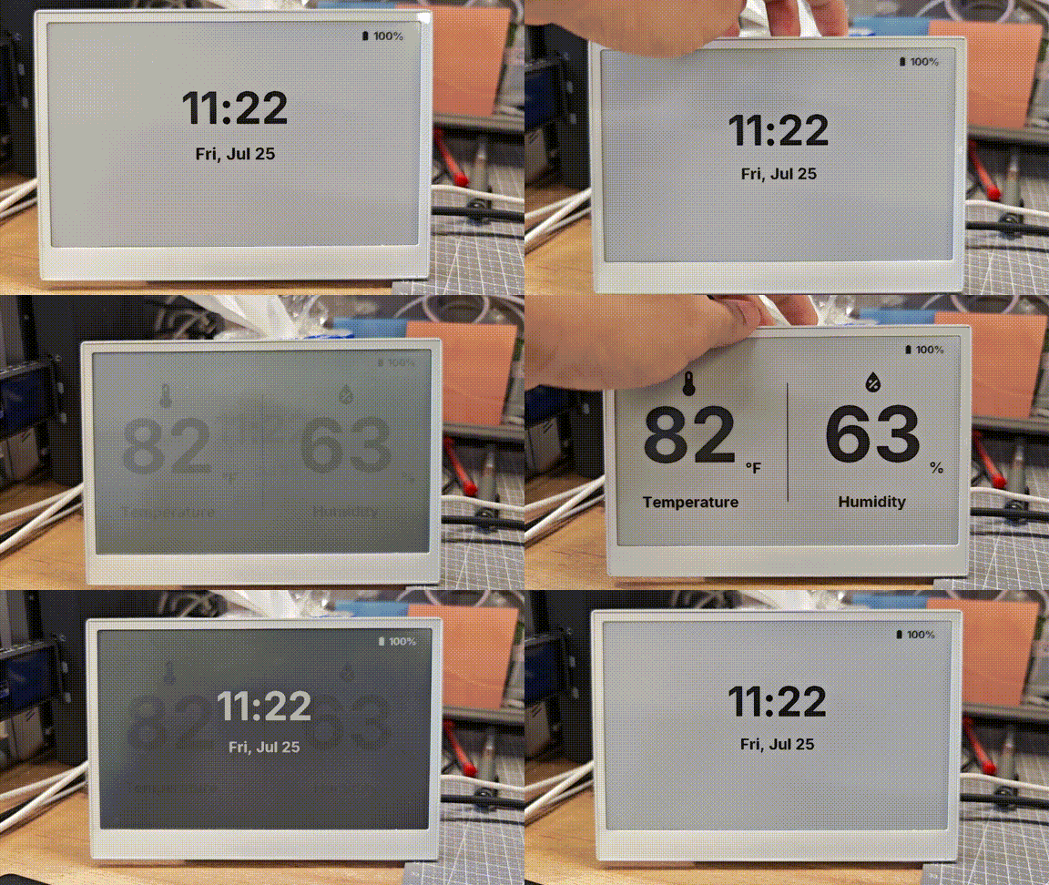
当你的配置成功上传并运行后,你的 reTerminal E 系列电子纸显示屏将显示一个包含环境数据、时间和电池状态的综合仪表盘:
理解这个综合示例
该示例实现了:
- 多页面:显示屏在两个页面之间切换——气候仪表盘和时间/日期显示
- 按键导航:使用 GPIO3 和 GPIO5 上的按键在页面之间导航
- 电池监测:电池电量通过相应图标显示,并根据电量水平变化
- 硬件初始化:在启动时启用 SD 卡和电池监测电路
- 温湿度显示:通过 I²C 使用板载 SHT4x 传感器
- 动态图标:Material Design Icons 会根据传感器数值变化
电容触摸(仅限 reTerminal E1003)
reTerminal E1003 上配备了 GT911 电容式触摸屏。reTerminal E1001、E1002 和 E1004 不包含此触摸控制器,因此在这些型号上请跳过本节。
reTerminal E1003 在共享 I2C 总线上使用 GT911 触摸控制器。在 ESPHome 中,你将它通过 touchscreen 组件附加到 it8951 显示屏,然后记录或响应触摸事件。
接线摘要
| 功能 | 引脚 / 总线 |
|---|---|
| 触摸中断 | GPIO2 |
| 触摸复位 | GPIO48 |
| I2C | SDA GPIO19, SCL GPIO20(与 SHT4x / PCF8563 共享) |
最小触摸示例
在你的 E1003 显示配置之后添加以下内容(display 块必须使用 id: epaper_display)。需要 ESPHome 2026.7.0 或更高版本。
i2c:
  scl: GPIO20
  sda: GPIO19

touchscreen:
  - platform: gt911
    id: e1003_touch
    display: epaper_display
    interrupt_pin: GPIO2
    reset_pin: GPIO48
    transform:
      mirror_x: true
    on_touch:
      - logger.log:
          format: "Touch: x=%d, y=%d"
          args: ["touch.x", "touch.y"]
你应该看到什么
- 烧录一个包含
it8951显示和gt911触摸屏块的 E1003 配置。 - 通过 USB 打开 ESPHome 日志(
logger使用hardware_uart: UART0)。 - 轻触面板——你应该在日志中看到
Touch: x=..., y=...这样的行。
你可以通过自动化扩展 on_touch,例如页面切换、按钮式热点或 Home Assistant 事件。保持 transform.mirror_x: true 与 E1003 显示的变换设置一致,以便触摸坐标与屏幕上绘制的内容相匹配。
常见问题
Q1:为什么没有数据?
在这种情况下,你应该前往 Settings -> Devices & Services -> Integrations 来 RECONGFIGURE 设备。还没有找到你的电子墨水屏?尝试重启 Home Assistant。
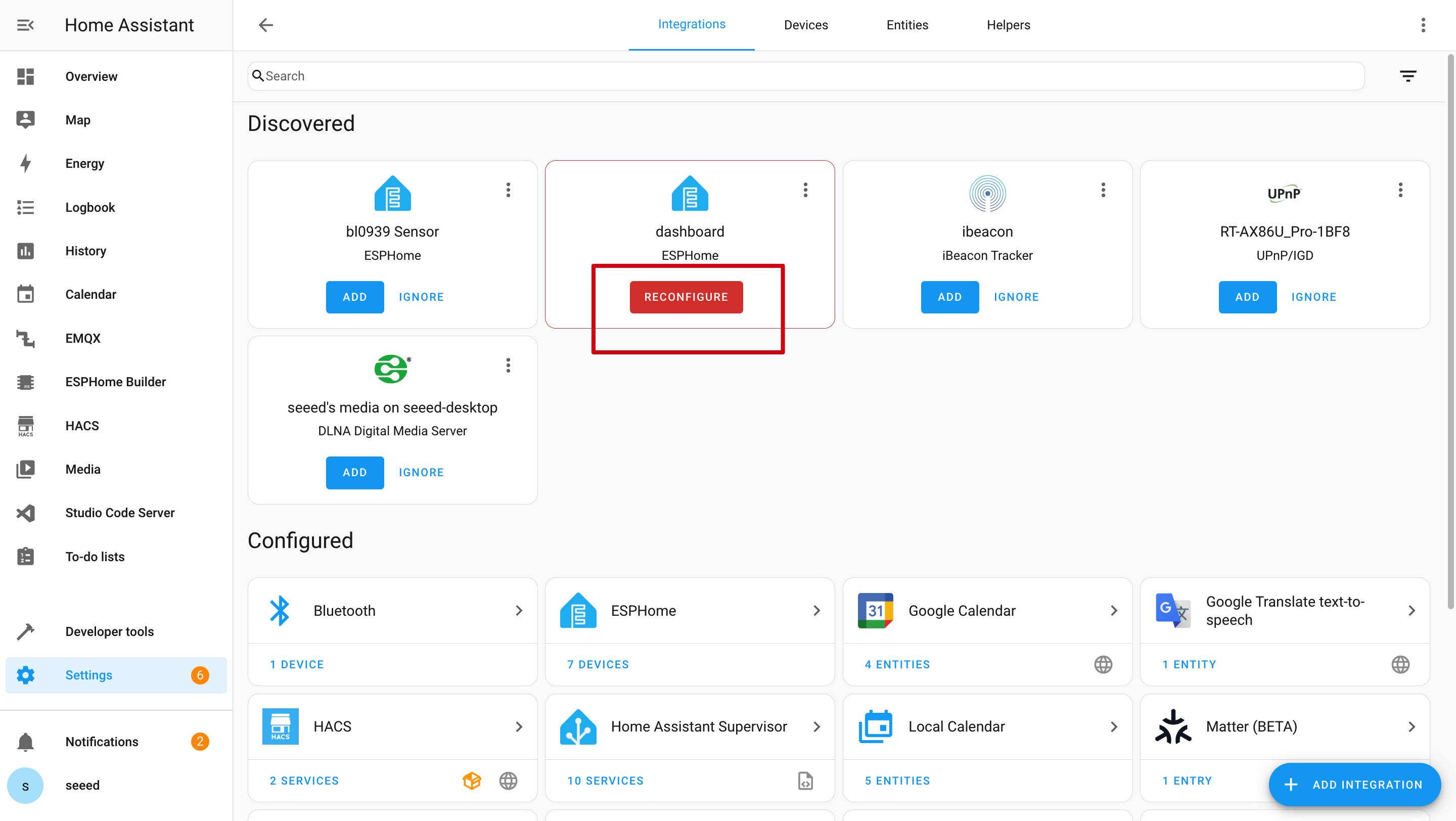
Q2:为什么在 Home Assistant 中获取不到这些数据?
在这种情况下,你应该前往 Settings -> Devices & Services -> Integrations,将你的设备 ADD 到 Home Assistant 中。

Q3:Wi-Fi 上传程序失败?

在这种情况下,你的设备要么离线,要么处于深度睡眠模式。请确保它已连接到你的网络,或先将其从睡眠模式唤醒,然后再尝试上传。
Q4:为什么通过 USB 没有串口日志?
reTerminal E 系列在 UART0 上使用 CH340K USB 转 UART 桥接芯片。请在你的 YAML 中保持以下日志设置:
logger:
  hardware_uart: UART0
技术支持与产品讨论
感谢你选择我们的产品!我们将为你提供多种支持,确保你在使用我们产品的过程中尽可能顺畅。我们提供多种沟通渠道,以满足不同的偏好和需求。