作为传感器使用 & 使用 Grove
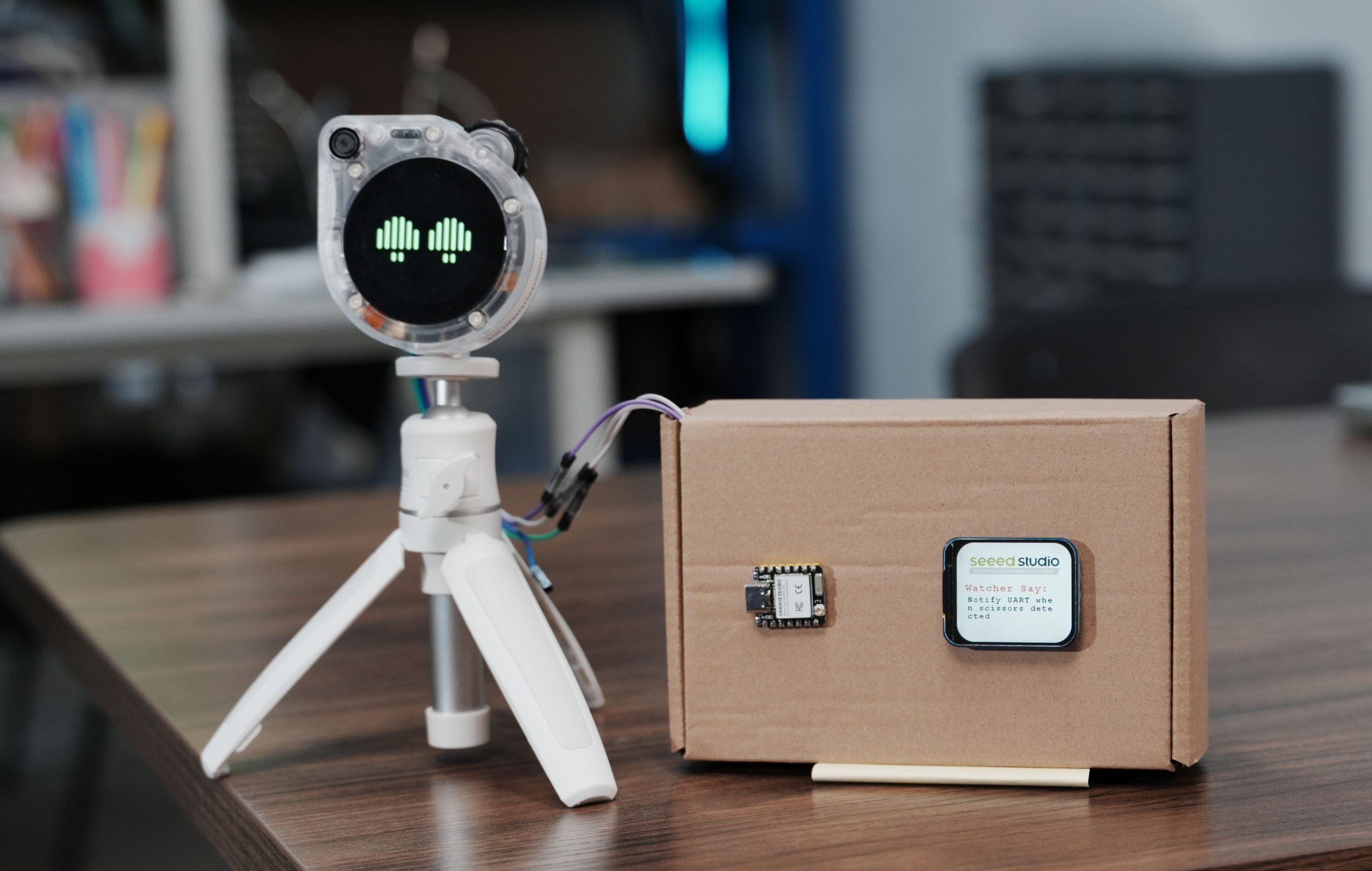
在本 wiki 中,我们将探索当 Watcher 作为传感器使用时,利用其 UART(通用异步收发器)功能所带来的令人兴奋的可能性。通过启用 UART 通信,Watcher 可以通过位于设备背面的 UART 接口传输有价值的数据,如捕获的图像和识别结果。这为将 Watcher 与各种硬件平台集成并创建创新应用程序开辟了无限可能。
在本 wiki 中,我们将深入了解从 Watcher 的 UART 接口读取和解释数据输出的详细信息。此外,我们还将提供关于如何使用流行的开发板和平台(包括 XIAO、Arduino、Raspberry Pi 和 Jetson)解析和利用这些数据的全面教程。
SenseCAP Watcher 高级配置
SenseCAP Watcher 是首个用于智能场所的物理 LLM 代理,能够监控场景、触发动作并基于命令进行交互。本视频将介绍 SenseCAP Watcher 如何基于任务分析选择场景触发模型:设备端模型和 LLM 模型。我们还将展示如何配置 RGB 灯和显示&声音警报,以及通知推送模式:APP、UART、HTTP。
Watcher UART 接线
当您准备使用 UART 进行消息警报时,请按以下方式将 Watcher 连接到您的 MCU。
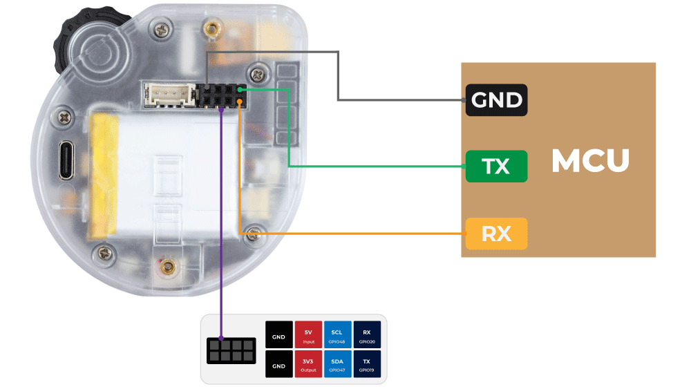
请注意,如果您的 Watcher 和 MCU 是分别供电的,那么您不需要连接 Watcher 和 MCU 的 3.3V 或 5V 引脚。
如果您计划使用 Watcher 为 MCU 供电,那么您可以在图中接线的基础上使用 3.3V 为 MCU 供电。(不要使用 5V 引脚,它们仅用于输入)
如果您计划使用 MCU 为 Watcher 供电,那么您需要使用 5V 输入。(3.3V 可能不足以让 Watcher 正常工作)
在 Watcher 中启用 UART 功能
要充分发挥 Watcher 的 UART 功能潜力,我们首先需要在设备中启用 UART 功能。这在将 Watcher 用作报警系统的场景中特别有用。当触发报警时,Watcher 可以激活其 UART 通信,允许它将关键信息(如捕获的图像和识别结果)传输到外部设备进行进一步处理和分析。
要启用 UART 报警功能,您有两个选项:
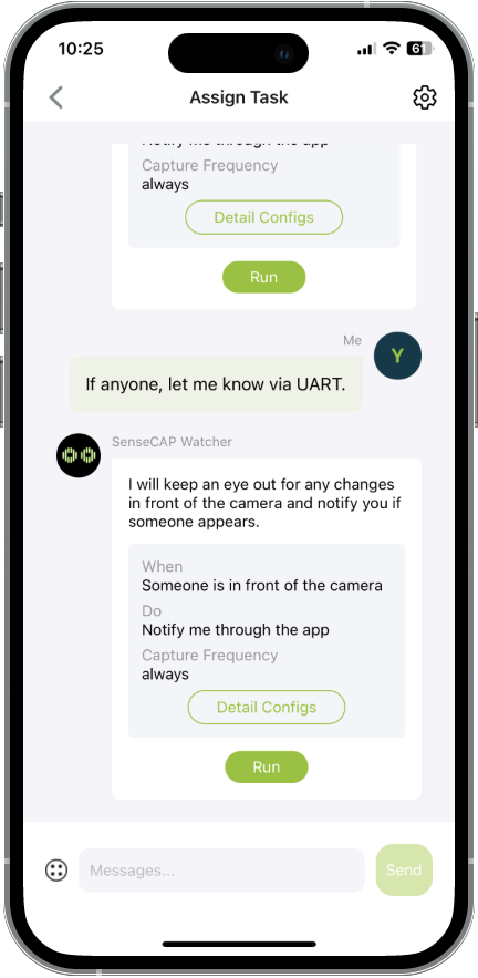
- 在使用 SenseCraft APP 分配任务时,明确请求 Watcher 通过 UART 通知您。
-
在任务的详细设置中手动启用 UART 报警功能:
- 访问您要配置的任务的 Detail Config。
- 找到 Action 部分。
- 勾选复选框以启用 Serial Port / UART Output。
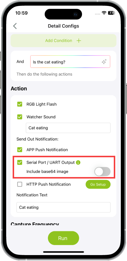
请根据您的实际应用场景选择是否需要启用图像输出。如果启用了 Include base64 image,那么您的 MCU 需要 至少 70k 内存 来缓存图像。
一旦您使用上述任一方法启用了 UART 报警功能,Watcher 将在检测到指定的报警内容时通过 UART 输出必要的报警信息。确保 Watcher 连接到适当的接收设备,如微控制器或带有串行终端的计算机,以捕获和处理通过 UART 传输的报警信息。
读取 Watcher 的 UART 输出
一旦启用了 UART 功能,Watcher 将开始通过其 UART 接口传输数据。在本节中,我们将提供详细的指南,说明如何读取和解释从 Watcher 的 UART 输出接收到的数据。我们将涵盖必要的硬件连接、通信协议和数据格式,以确保顺利成功的数据检索过程。
默认情况下,Watcher 使用以下 UART 配置:波特率 115200,8 数据位,无奇偶校验,1 停止位,以及 无硬件流控制。当连接到 Watcher 的 UART 接口时,确保您的接收设备配置了相同的设置以确保正确通信。
当 Watcher 通过 UART 发送报警信息时,它遵循基于 tf_module_uart_alarm.h 头文件中定义的 tf_module_uart_alarm_t 结构的特定协议和格式。Watcher 的 UART 报警模块的 UART 协议和格式如下:
输出格式
UART 输出的格式由 output_format 字段控制。
- 当
output_format设置为 0 时,输出为二进制格式。 - 当
output_format设置为 1 时,输出为 JSON 格式。
output_format 默认设置为 1 以 JSON 格式输出。
二进制输出格式
当 output_format 设置为 0 时,UART 输出数据包的结构如下:
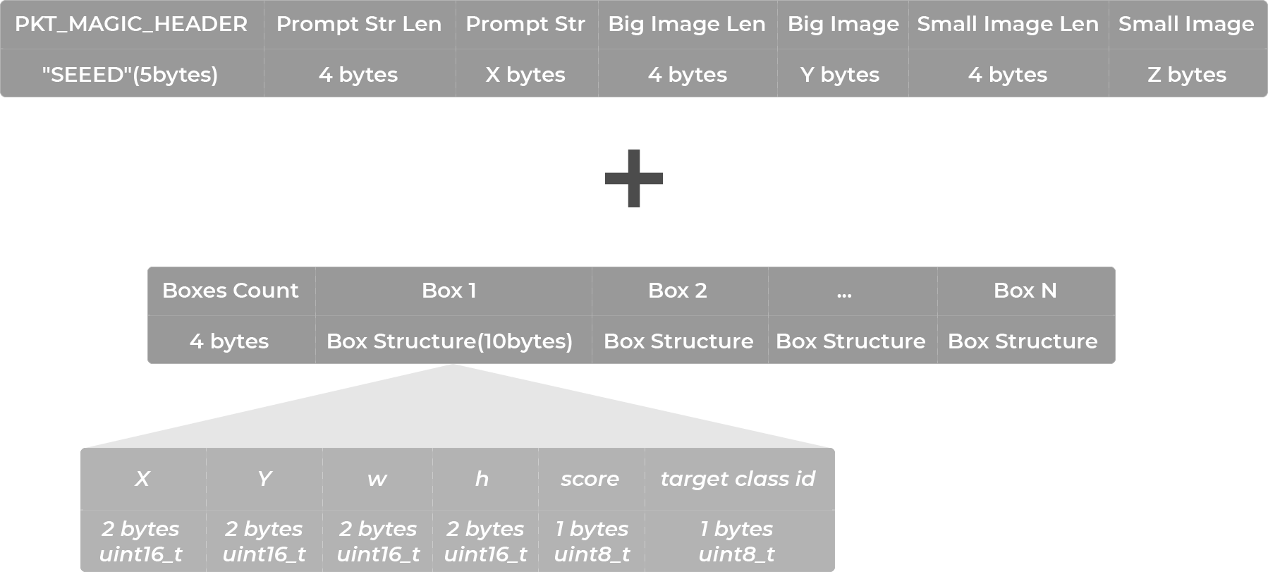
PKT_MAGIC_HEADER:数据包的魔术头,固定为 "SEEED"(5 字节)。Prompt Str Len:提示字符串的长度,小端序 4 字节无符号整数。Prompt Str:提示字符串,用于简要说明 Watcher 正在执行的任务。如果设置了text参数,则使用其值。Big Image Len:大图像的长度,小端序 4 字节无符号整数。仅在include_big_image为true时包含。Big Image:640*480 JPG 图像,base64 编码,不包含检测到的对象框。仅在include_big_image为true时包含。Small Image Len:小图像的长度,小端序 4 字节无符号整数。仅在include_small_image为true时包含。Small Image:240*240 JPG 图像,base64 编码,为检测到的对象绘制了框。仅在include_small_image为true时包含。Boxes Count:检测到的对象框数量,小端序 4 字节无符号整数。仅在include_boxes为true时包含。Box Structure:检测到的对象框的结构,每个框占用 10 字节,包括坐标、分数和目标类别 ID。仅在include_boxes为true时包含。
目前不会收到识别框(boxes)消息,因为 Watcher 的相应功能仍在开发中,尚未在最新的 v1.1 版本中报告。
JSON 输出格式
当 output_format 设置为 1 时,UART 输出数据包的结构如下:
{
      "prompt": "People detected",
      "big_image": "base64 encoded JPG image, if include_big_image is enabled, otherwise this field is omitted",
      "inference":{
        "boxes": [
            {
                "x": 100,
                "y": 100,
                "w": 50,
                "h": 60,
                "score": 0.8,
                "target_cls_id": 1
            }
        ],
        "classes_name": ["person"]
      },

}
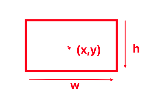
其中,(x,y) 是识别对象的中心点位置,(w,h) 是识别框的高度和宽度,如下图所示。score 是置信度,target_cls_id 是识别对象的 id。
配置选项
output_format:控制 UART 输出的格式,默认为 1(JSON 格式)。text:用于填充输出数据包的prompt字段。include_big_image:布尔值(true | false),控制输出中是否包含大图像,默认为true。include_boxes:布尔值(true | false),控制输出中是否包含框,默认为true。
注意:如果省略任何配置字段,将使用默认值。
此时将不会收到识别框(boxes)消息,因为 Watcher 的相应功能仍在开发中,尚未在最新的 v1.1 版本中报告。
XIAO ESP32 系列 & Watcher
了解如何将 Watcher 连接到 XIAO ESP32 系列开发板并使用 Arduino 解析 UART 数据。本节将指导您如何将 Watcher 连接到 XIAO ESP32 系列开发板并使用 Arduino 解析 UART 数据。
接线
本教程支持以下 XIAO 系列:
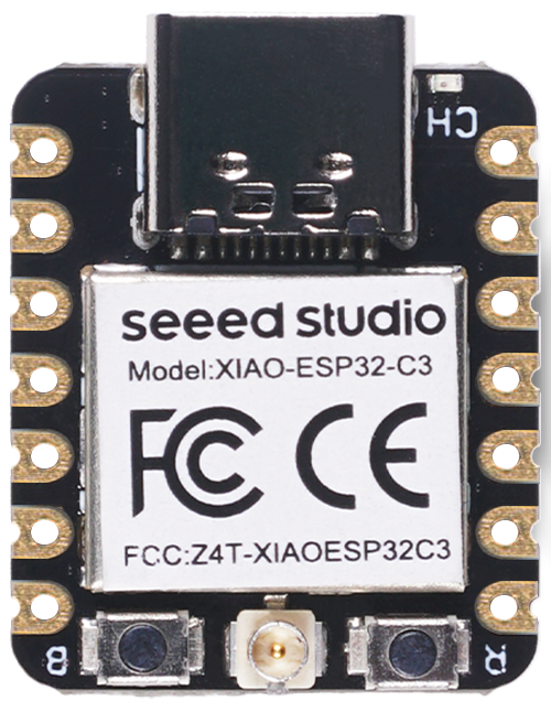


这并不意味着其他 XIAO 系列不受支持。主要是因为 Watcher 报告的消息数据占用大约 100k(至少 70k)的内存,我们建议您在 Watcher 开发的 UART 部分使用 ESP32 系列的 XIAO。如果您不需要解析图像数据,那么其他 XIAO 的内存是完全足够的。
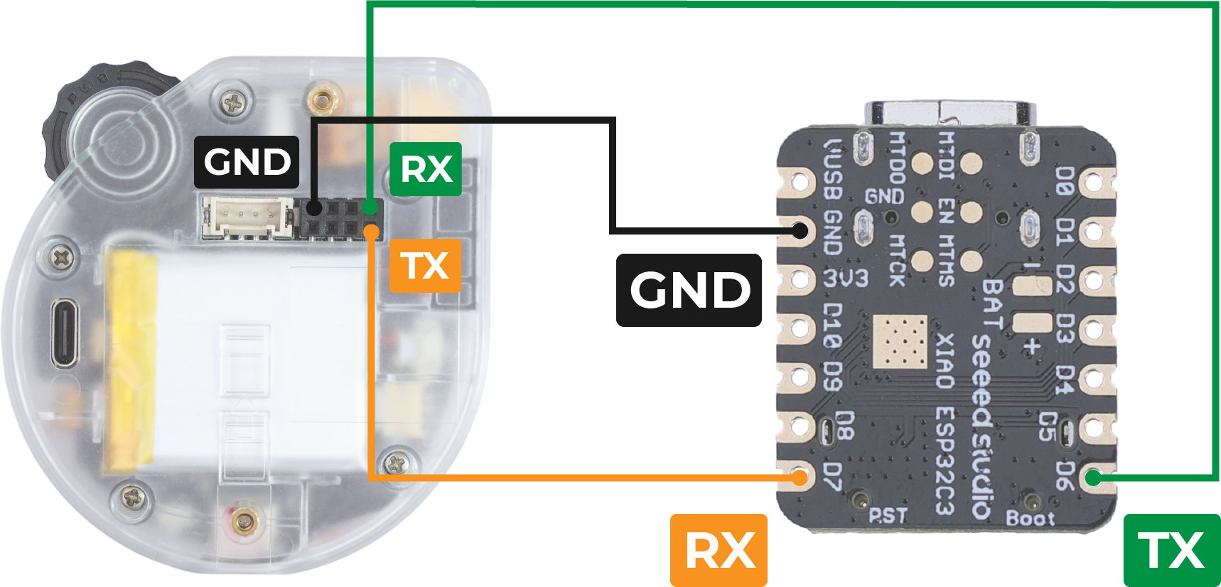
-
将 Watcher 的 TX 引脚连接到 XIAO 的 UART 接口的 RX 引脚。
-
将 Watcher 的 RX 引脚连接到 XIAO 的 UART 接口的 TX 引脚。
-
将 Watcher 的 GND 引脚连接到 XIAO 上的 GND 引脚。
代码说明
您可以使用任何 XIAO ESP32 系列开发板,或任何其他 ESP32 系列板来使用以下程序读取 Watcher 的 UART 数据流。
目前只能输出 JSON 数据流,因此只提供解析 JSON 数据流的程序。
其他 XIAO 并不总是受支持,主要是因为解析 JSON 流需要至少 70k 的内存。
#include <ArduinoJson.h>

long int count = 0;  // Number of alarms

void setup() {
  Serial.begin(115200);
  Serial1.begin(115200, SERIAL_8N1, D7, D6);  // RX, TX
  while(!Serial);
  delay(100);

  Serial.println("Device Ready. Waiting for Watcher's JSON data...");
}

void loop() {
  if (Serial1.available()) {
    // Set up enough space to store the parsed JSON objects
    const size_t capacity = 1024 * 100 + 512; // At least 70k, insurance 100k
    DynamicJsonDocument doc(capacity);

    // Streaming parsing from Serial1
    DeserializationError error = deserializeJson(doc, Serial1);

    if (error) {
      Serial.print("deserializeJson() failed: ");
      Serial.println(error.c_str());
      return;
    }

    // Print the parsed key-value pairs
    if (doc.containsKey("prompt")) {
      Serial.print("prompt: ");
      Serial.println(doc["prompt"].as<String>());
    }

    if (doc.containsKey("inference")) {
      Serial.print("inference: ");
      Serial.println(doc["inference"].as<String>());
    }

   if (doc.containsKey("inference")) {
     JsonArray boxes = doc["inference"]["boxes"][0].as<JsonArray>();
      Serial.println();
      Serial.println("You can get the number inside the boxes.");
      Serial.print("Box -> ");
      Serial.print("x: ");
      Serial.print(boxes[0].as<int>());
      Serial.print(", y: ");
      Serial.print(boxes[1].as<int>());
      Serial.print(", widths: ");
      Serial.print(boxes[2].as<int>());
      Serial.print(", height: ");
      Serial.print(boxes[3].as<int>());
      Serial.print(", score: ");
      Serial.print(boxes[4].as<int>());
      Serial.print(", target_cls_id: ");
      Serial.println(boxes[5].as<int>());
   }

    // You need to turn on "Inculde base64 iamge" button in your app, default is off.
    //And then, uncomment the following code.
    /*
    if (doc.containsKey("big_image")) {
      Serial.print("big_image: ");
      String big_imageData = doc["big_image"].as<String>();
      // Print only the first 100 characters of the image data for example
      Serial.println(big_imageData.substring(0, 100) + "...");
    }
    */


    count++;
    if(count > 2147483646){  // Spillage prevention
      count = 0;
    }
    Serial.print("The ");
    Serial.print(count);
    Serial.println(" alarm message reception is complete. Wait for the next message...");
    Serial.println("------------------------------------------------------------------");
  }
}
提供的代码演示了如何使用 Arduino IDE 和 ArduinoJson 库从 Watcher 接收和解析 JSON 数据。以下是代码的简要说明:
- 包含了必要的库 ArduinoJson 来处理 JSON 解析。您可以在 Arduino 的库管理器中搜索并安装它。
-
在
setup()函数中,初始化了 USB 串口(用于调试)和 UART 串口(用于从 Watcher 接收数据)的串口通信。 -
在
loop()函数中,代码检查 UART 串口上是否有可用数据。 -
如果有数据可用,会创建一个具有指定容量的
DynamicJsonDocument来存储解析的 JSON 对象。 -
使用
deserializeJson()函数解析 JSON 数据,并处理任何解析错误。 -
然后代码检查解析的 JSON 对象中是否存在特定键,如 "prompt"、"big_image" 和 "small_image"。
目前还无法解析识别框(boxes)的信息,因为 Watcher 的相应功能仍在开发中,在最新的 v1.0.1 版本中尚未报告此信息。
-
如果找到某个键,其对应的值会被打印到 USB 串口用于调试目的。
-
代码还使用
count变量跟踪接收到的报警消息数量。 -
最后,打印一条消息表示每个报警消息接收的完成,然后代码等待下一条消息。
将代码上传到 XIAO ESP32 系列
要将代码上传到您的 XIAO ESP32 系列开发板,请按照以下步骤操作:
-
使用 USB 线将您的 XIAO ESP32 系列开发板连接到计算机。
-
打开 Arduino IDE 并确保您已为 XIAO ESP32 系列安装了必要的开发板支持包。
-
在 Arduino IDE 的工具菜单中选择适当的开发板和端口。
-
在 Arduino IDE 中打开提供的代码。
-
点击 上传 按钮编译代码并上传到您的 XIAO ESP32 系列开发板。
预期结果
一旦代码上传并在您的 XIAO ESP32 系列开发板上运行,在 Watcher 识别到目标报警后,您应该看到以下行为:
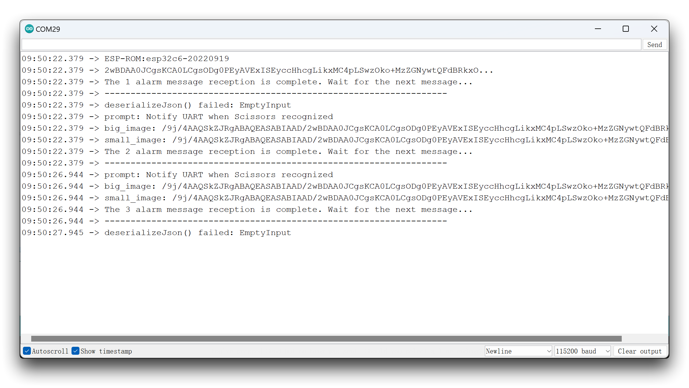
您也可以尝试使用其他 Arduino 开发板,但请确保它有足够的内存。
Raspberry Pi 与 Watcher
探索将 Watcher 连接到 Raspberry Pi 并使用 Python 脚本解析和分析 UART 数据的过程。
接线
本节将以 Raspberry Pi 5 为例进行说明,如果您需要,可以通过下面的链接下单购买。
如果您使用的是其他 Raspberry Pi 系列,代码和使用教程基本相同。
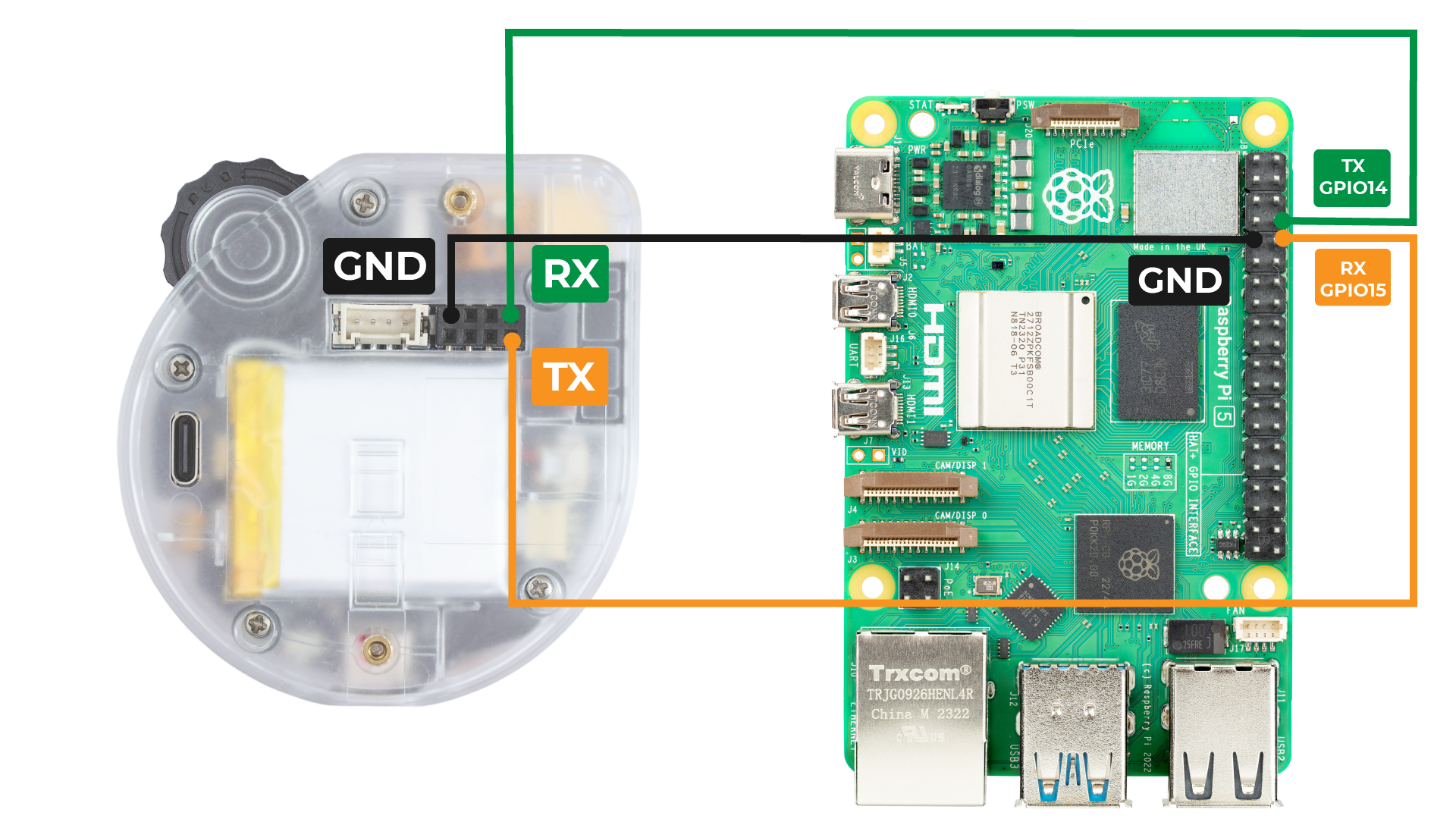
-
将 Watcher 的 TX 引脚连接到 Raspberry Pi 的 RX 引脚(GPIO 15)。
-
将 Watcher 的 RX 引脚连接到 Raspberry Pi 的 TX 引脚(GPIO 14)。
-
将 Watcher 的 GND 引脚连接到 Raspberry Pi 的 GND 引脚。
代码说明
在运行 Python 脚本之前,请确保安装所需的依赖项:
sudo apt update
sudo apt install python3-pip
pip3 install pyserial pillow
检查 Raspberry Pi 上 UART 接口的设备名称:
ls /dev/ttyAMA*
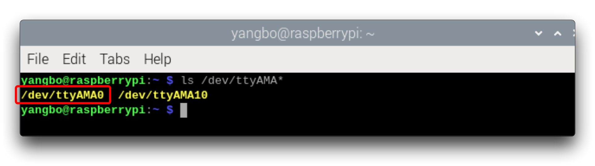
第一个 Python 脚本通过 UART 从 Watcher 读取 JSON 数据并打印:
import serial

# Set up the serial port
ser = serial.Serial('/dev/ttyAMA0', 115200, timeout=1)

def read_json_from_serial():
    while True:
        if ser.in_waiting > 0:
            data = ser.readline()
            print(data.decode().strip())

if __name__ == "__main__":
    print("Starting serial JSON reader on Raspberry Pi...")
    read_json_from_serial()
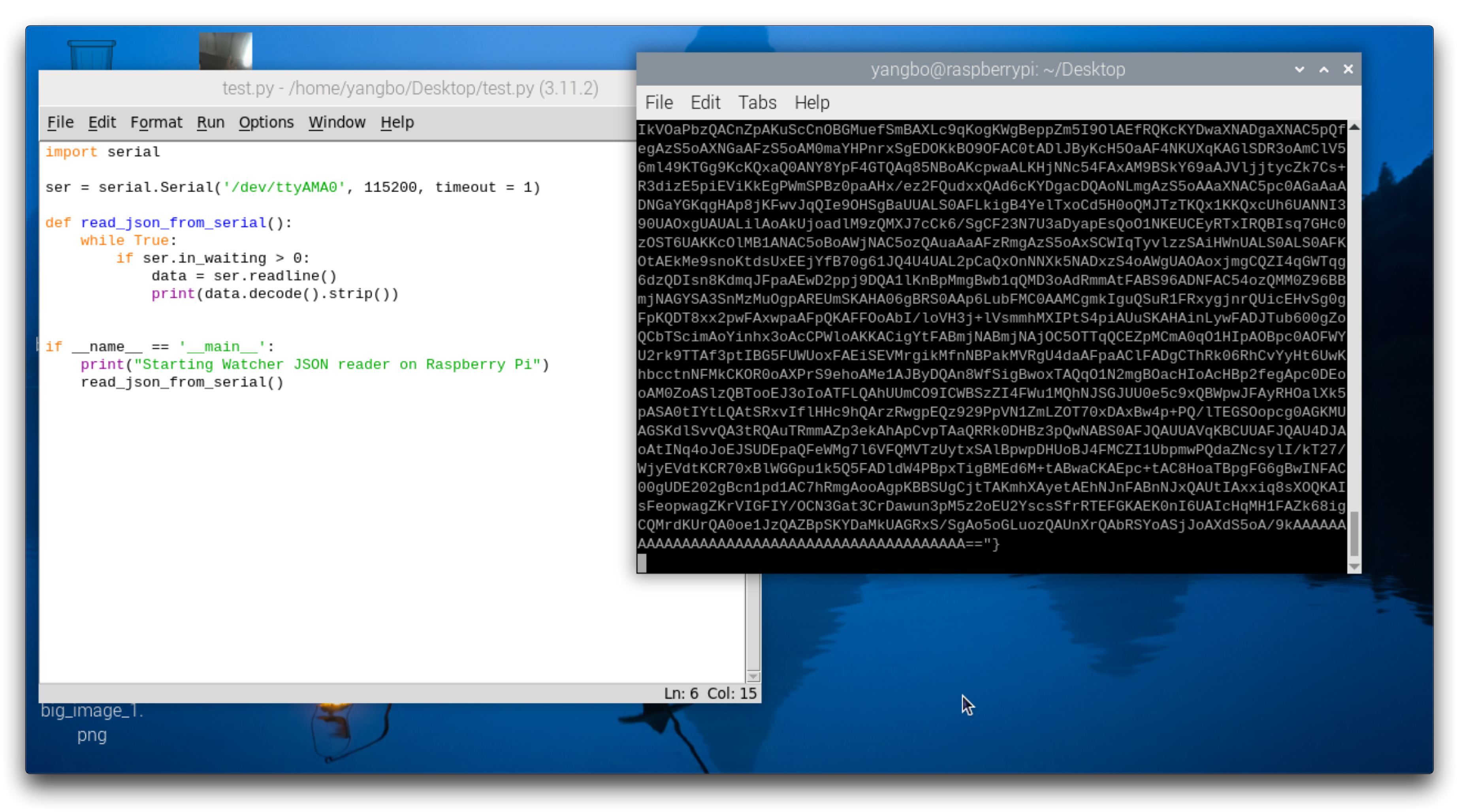
-
我的 UART 接口对应
/dev/ttyAMA0,如果您的不是,请自行修改。 -
这是一个测试脚本,您可以使用它来检查树莓派/Watcher 的 UART 是否正常工作。
第二个 Python 脚本基于第一个脚本构建,并添加了 JSON 解析和图像数据保存功能:
import json
import serial
import base64
from PIL import Image
import io

# Set up the serial port
ser = serial.Serial('/dev/ttyAMA0', 115200, timeout=1)

# Initialize image counters
big_image_counter = 1
small_image_counter = 1

def read_json_from_serial():
    buffer = ""
    try:
        while True:
            if ser.in_waiting > 0:
                data = ser.read(ser.in_waiting).decode()
                buffer += data

                if '}' in buffer:
                    end = buffer.rfind('}')
                    json_data = buffer[:end+1]
                    buffer = buffer[end+1:]

                    try:
                        data = json.loads(json_data)
                        print("Received JSON data, processing...")
                        process_json_data(data)
                    except json.JSONDecodeError:
                        print("Error decoding JSON")
                        buffer = json_data + buffer
    except Exception as e:
        print(f"An error occurred: {e}")

def process_json_data(data):
    global big_image_counter, small_image_counter  # Declare global variables

    # Process prompt info
    if "prompt" in data:
        print(f"Prompt: {data['prompt']}")

    # Process boxes info
    #if "boxes" in data:
        #for index, box in enumerate(data['boxes']):
            #print(f"Box {index + 1} - x: {box['x']}, y: {box['y']}, w: {box['w']}, h: {box['h']}, score: {box['score']}, target_cls_id: {box['target_cls_id']}")

    if "big_image" in data:
        filename = f'big_image_{big_image_counter}.png'
        decode_and_save_image(data['big_image'], filename)
        print(f"Big image processed and saved as {filename}.")
        big_image_counter += 1  # Update global variable

    if "small_image" in data:
        filename = f'small_image_{small_image_counter}.png'
        decode_and_save_image(data['small_image'], filename)
        print(f"Small image processed and saved as {filename}.")
        small_image_counter += 1  # Update global variable

def decode_and_save_image(base64_data, filename):
    image_bytes = base64.b64decode(base64_data)
    image = Image.open(io.BytesIO(image_bytes))
    image.save(filename)  # Save as PNG file
    return image

if __name__ == "__main__":
    print("Starting serial JSON reader on Raspberry Pi...")
    read_json_from_serial()
目前只能输出 JSON 数据流,因此只提供解析 JSON 数据流的程序。
此脚本执行以下操作:
-
在循环中从 UART 读取 JSON 数据
-
解码 JSON 数据并调用
process_json_data来处理它 -
从 JSON 中提取提示信息和图像数据
目前还无法解析识别框(boxes)的信息,因为 Watcher 的相应功能仍在开发中,在最新的 v1.0.1 版本中尚未报告此信息。
-
解码 base64 编码的图像数据并使用
decode_and_save_image保存为 PNG 文件 -
打印提取的信息和已保存图像的文件名
在树莓派上运行代码
- 在树莓派上创建一个新的 Python 文件,例如 watcher_uart.py:
nano watcher_uart.py
-
将完整的 Python 代码复制并粘贴到文件中。
-
按 Ctrl+X,然后按 Y 和 Enter 键保存并退出编辑器。
-
运行 Python 脚本:
python watcher_uart.py
预期结果
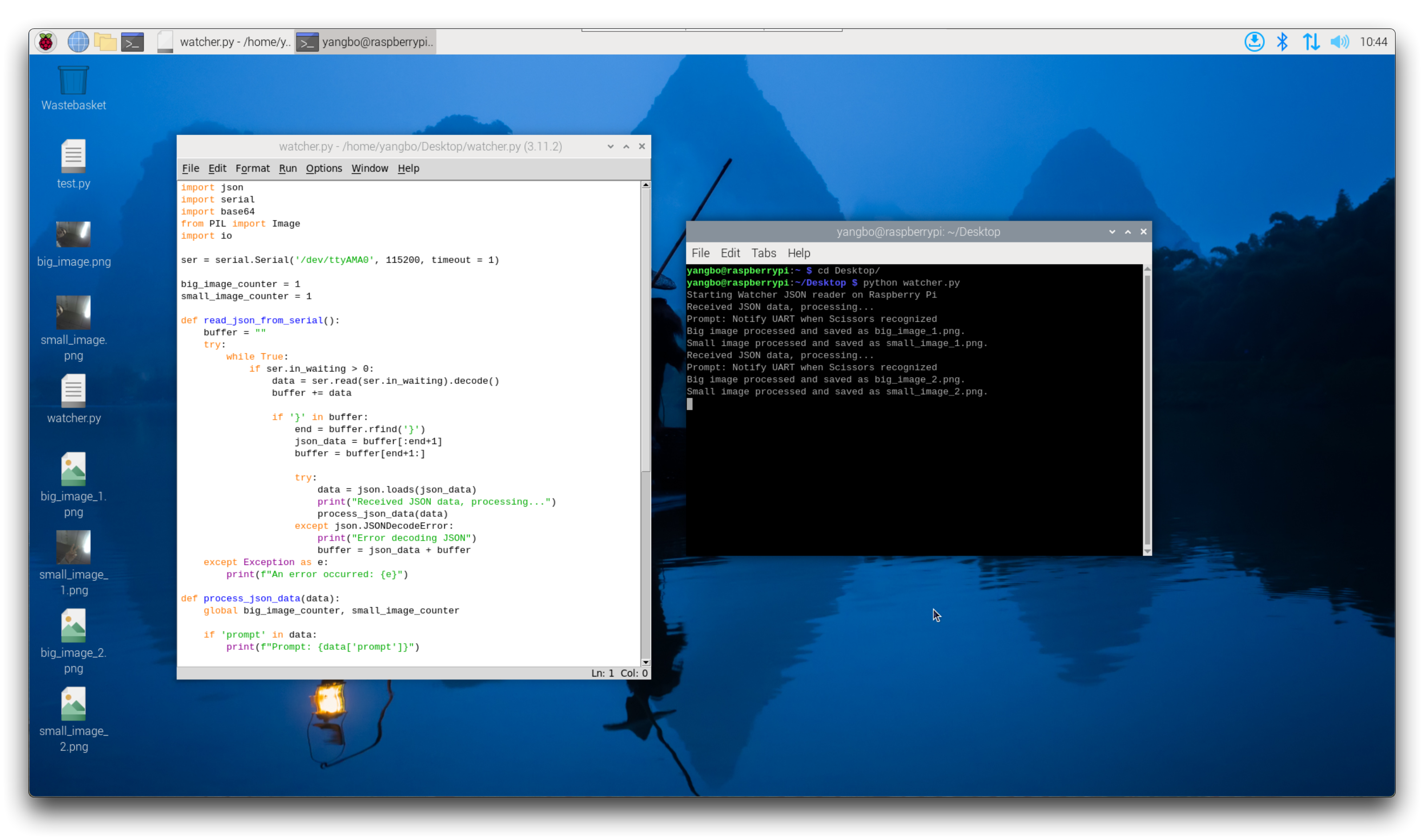
运行脚本后:
-
从 Watcher 接收到的解析 JSON 数据将实时打印在终端中。
-
接收到的大图像和小图像将自动保存为 big_image_x.png 和 small_image_x.png 文件。
就是这样!您现在已经学会了如何将 Watcher 连接到树莓派,使用 Python 读取 UART 数据,解析 JSON,并保存传输的图像。请随意进一步实验,例如尝试在连接到树莓派的屏幕上实时显示接收到的数据。
reComputer Jetson & Watch
探索将 Watcher 连接到 reComputer(基于 NVIDIA Jetson 的设备)并使用 Python 脚本解析和分析 UART 数据的过程。
接线
本教程将以适合开发者的 J401 reComputer 载板为例进行说明,如果您想购买 reComputer,可以通过下面的链接获取。
理论上,本节的内容和代码适用于所有 NVIDIA Jetson 系列产品。
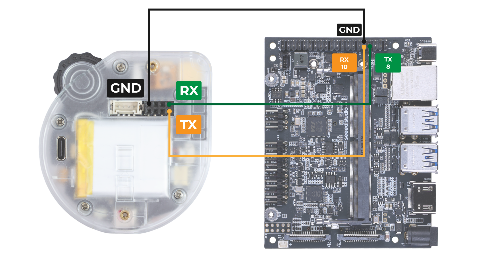
-
将 Watcher 的 TX 引脚连接到 reComputer UART 接口的 RX 引脚。
-
将 Watcher 的 RX 引脚连接到 reComputer UART 接口的 TX 引脚。
-
将 Watcher 的 GND 引脚连接到 reComputer 上的 GND 引脚。
代码说明
在运行 Python 脚本之前,请确保安装所需的依赖项:
sudo apt-get update
sudo apt-get install python3-serial
sudo apt-get install python3-pillow
如果您不打算在 UART 上使用串行控制台,您应该禁用串行控制台:
systemctl stop nvgetty
systemctl disable nvgetty
udevadm trigger
此时您可能需要重启 reComputer 以使更改生效。
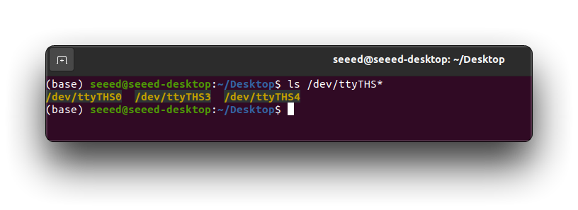
检查 reComputer 上 UART 接口的设备名称:
ls /dev/ttyTHS*
第一个 Python 脚本通过 UART 从 Watcher 读取 JSON 数据并打印:
import serial

# Set up the serial port
ser = serial.Serial('/dev/ttyTHS0', 115200, timeout=1)

def read_json_from_serial():
    while True:
        if ser.in_waiting > 0:
            data = ser.readline()
            print(data.decode().strip())

if __name__ == "__main__":
    print("Starting serial JSON reader on reComputer...")
    read_json_from_serial()
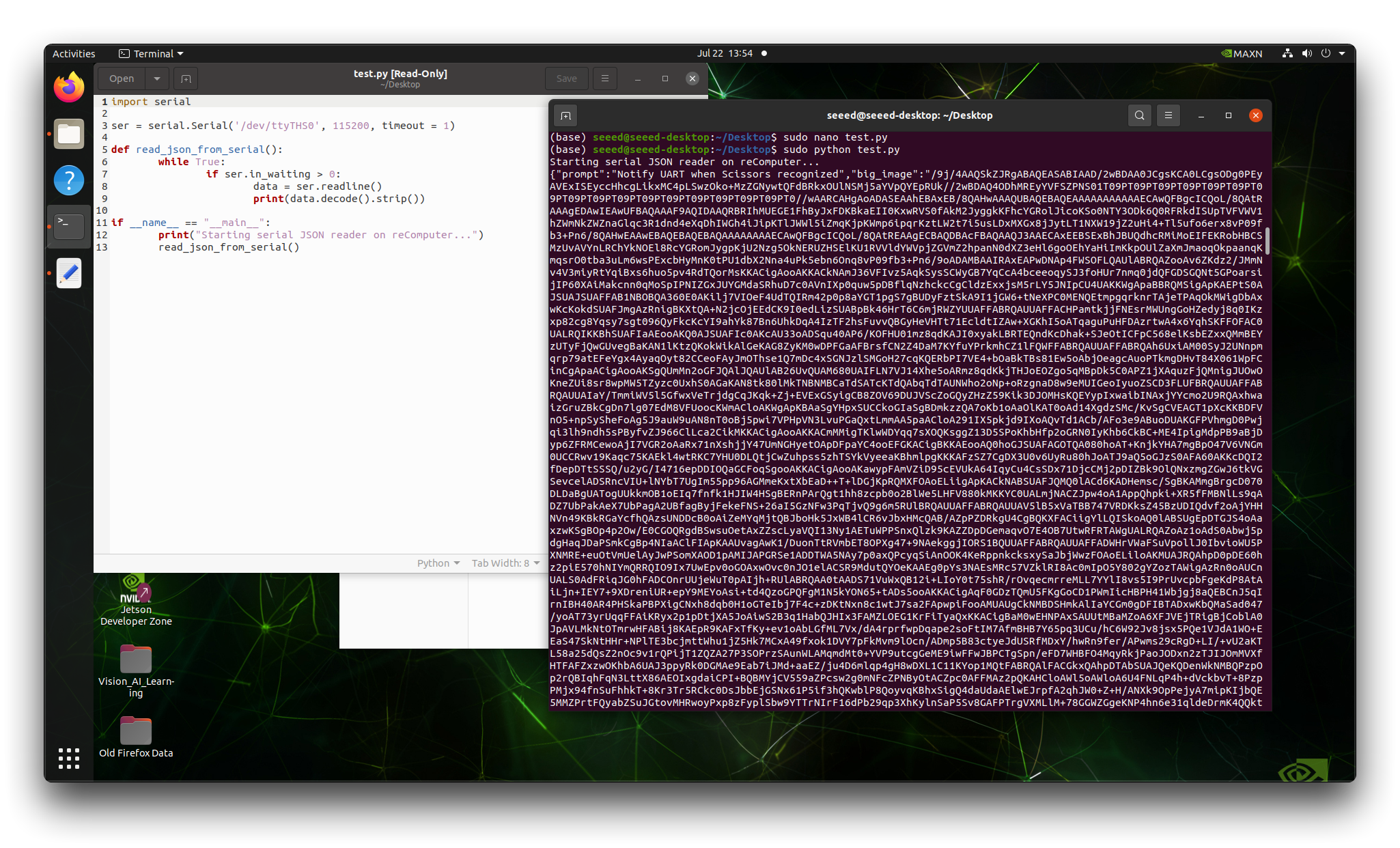
-
我的 UART 接口对应
/dev/ttyTHS0,如果您的不是,请自行修改。 -
这是一个测试脚本,您可以使用它来检查 reComputer/Watcher 的 UART 是否正常工作。
第二个 Python 脚本基于第一个脚本构建,并添加了 JSON 解析和图像数据保存功能:
import json
import serial
import base64
from PIL import Image
import io

# Set up the serial port
ser = serial.Serial('/dev/ttyTHS0', 115200, timeout=1)

# Initialize image counters
big_image_counter = 1
small_image_counter = 1

def read_json_from_serial():
    buffer = ""
    try:
        while True:
            if ser.in_waiting > 0:
                data = ser.read(ser.in_waiting).decode()
                buffer += data

                if '}' in buffer:
                    end = buffer.rfind('}')
                    json_data = buffer[:end+1]
                    buffer = buffer[end+1:]

                    try:
                        data = json.loads(json_data)
                        print("Received JSON data, processing...")
                        process_json_data(data)
                    except json.JSONDecodeError:
                        print("Error decoding JSON")
                        buffer = json_data + buffer
    except Exception as e:
        print(f"An error occurred: {e}")

def process_json_data(data):
    global big_image_counter, small_image_counter  # Declare global variables

    # Process prompt info
    if "prompt" in data:
        print(f"Prompt: {data['prompt']}")

    # Process boxes info
    #if "boxes" in data:
        #for index, box in enumerate(data['boxes']):
            #print(f"Box {index + 1} - x: {box['x']}, y: {box['y']}, w: {box['w']}, h: {box['h']}, score: {box['score']}, target_cls_id: {box['target_cls_id']}")

    if "big_image" in data:
        filename = f'big_image_{big_image_counter}.png'
        decode_and_save_image(data['big_image'], filename)
        print(f"Big image processed and saved as {filename}.")
        big_image_counter += 1  # Update global variable

    if "small_image" in data:
        filename = f'small_image_{small_image_counter}.png'
        decode_and_save_image(data['small_image'], filename)
        print(f"Small image processed and saved as {filename}.")
        small_image_counter += 1  # Update global variable

def decode_and_save_image(base64_data, filename):
    image_bytes = base64.b64decode(base64_data)
    image = Image.open(io.BytesIO(image_bytes))
    image.save(filename)  # Save as PNG file
    return image

if __name__ == "__main__":
    print("Starting serial JSON reader on reComputer...")
    read_json_from_serial()
目前只能输出 JSON 数据流,因此只提供解析 JSON 数据流的程序。
此脚本执行以下操作:
-
在循环中从 UART 读取 JSON 数据
-
解码 JSON 数据并调用 process_json_data 来处理它
-
从 JSON 中提取提示信息和图像数据
-
使用
decode_and_save_image解码 base64 编码的图像数据并保存为 PNG 文件
目前还无法解析识别框(boxes)的相关信息,因为 Watcher 的相应功能仍在开发中,在最新的 v1.0.1 版本中尚未报告此信息。
- 打印提取的信息和已保存图像的文件名
将代码上传到 reComputer
在 reComputer 上创建一个新的 Python 文件,例如 watcher_uart.py:
nano watcher_uart.py
将完整的 Python 代码复制并粘贴到文件中。按 Ctrl+X,然后按 Y 和 Enter 保存并退出编辑器。运行 Python 脚本:
sudo python watcher_uart.py
预期结果
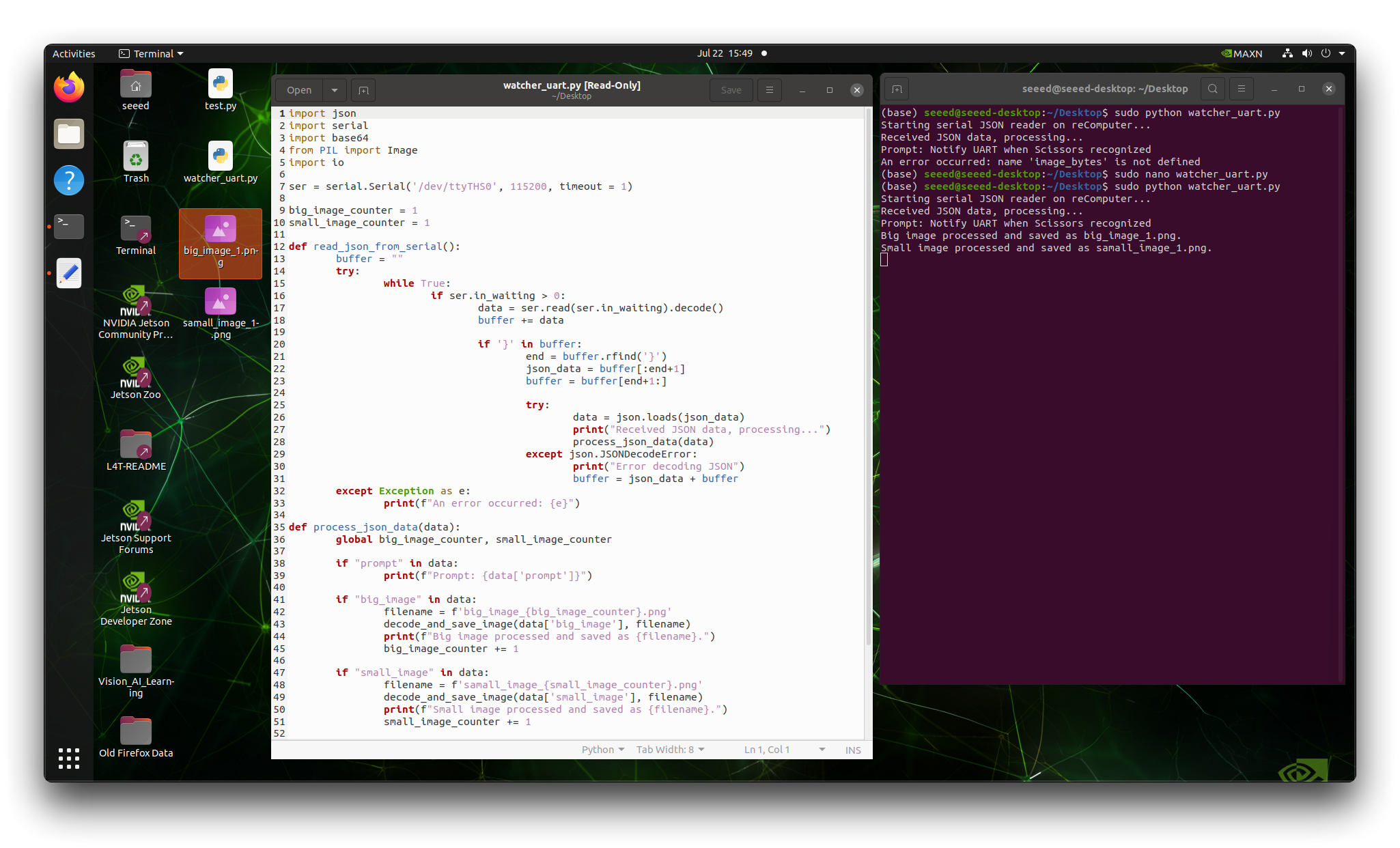
运行脚本后:
-
从 Watcher 接收到的解析后的 JSON 数据将实时打印在终端中,包括提示信息。
-
接收到的大图像和小图像将自动保存为 big_image_x.png 和 small_image_x.png 文件。
就是这样!您现在已经学会了如何将 Watcher 连接到 reComputer,使用 Python 读取 UART 数据,解析 JSON,并保存传输的图像。请随意进一步实验,并根据您在 reComputer 平台上的具体用例调整代码。
资源
-
Watcher 快速入门系列 5# : 为 Watcher 训练模型
技术支持与产品讨论
感谢您选择我们的产品!我们在这里为您提供不同的支持,以确保您使用我们产品的体验尽可能顺畅。我们提供多种沟通渠道,以满足不同的偏好和需求。