XIAO ESP32S3(Sense) 与 FreeRTOS
本 wiki 涵盖了 Seeed Studio XIAO ESP32S3 的 FreeRTOS 支持。通过本指南的帮助,您将能够利用该开发板的可用功能集。
什么是 FreeRTOS

FreeRTOS 是一个由 C 库组成的集合,包含一个实时内核和一组实现互补功能的模块化库。FreeRTOS 内核是一个实时内核(或实时调度器),使基于 FreeRTOS 构建的应用程序能够满足其硬实时要求。它使应用程序能够组织为独立执行线程的集合。
FreeRTOS 移植
FreeRTOS 是一个开源的 RTOS(实时操作系统)内核,作为组件集成到 ESP-IDF 中。因此,所有 ESP-IDF 应用程序和许多 ESP-IDF 组件都是基于 FreeRTOS 编写的。FreeRTOS 内核已移植到 ESP 芯片的所有可用架构(即 Xtensa 和 RISC-V)。
我们将使用 FreeRTOS 的 ESP IDF 移植版本。
硬件准备
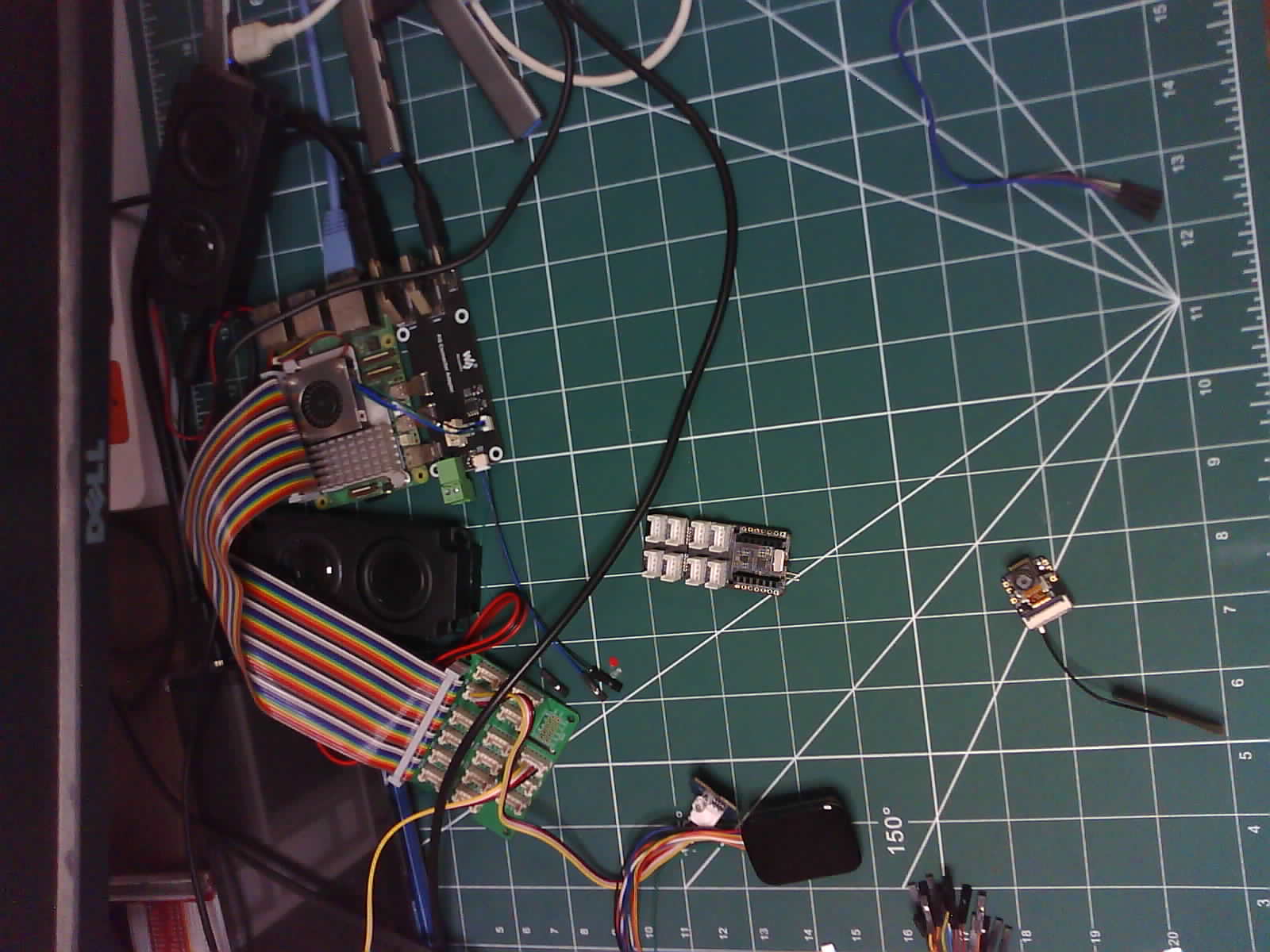
我使用的是 Seed Studio XIAO ESP32S3 Sense 以及板载摄像头、麦克风和 SD 卡读卡器,还有 ESP32S3 的 WiFi 功能。
| Seeed Studio XIAO ESP32S3(Sense) |
|---|
 |
附加组件
- Grove - 扩展板 - I2C 显示屏 RTC 和按钮
- 空气质量传感器 v1.3
- Grove - 温度、湿度、压力和气体传感器(适用于 Arduino - BME680)
- Seeed Studio XIAO 扩展板亚克力外壳
软件准备
我使用的是 Visual Studio Code(Windows)配合 ESP-IDF。
- VSCode 安装
- ESP-IDF 安装指南
- Git 仓库
| VS Code | ESP-IDF for VSCode |
|---|---|
入门指南
设置 ESP-IDF
设置好 Visual Studio 扩展 后,打开终端并粘贴以下命令,以便从普通终端环境(VScode 外部)访问 ESP-IDF 命令行工具。
VS-Code 的 ESP-IDF 扩展的正常安装将处理 90% 的使用情况,只有在您需要在环境外部使用 ESP 命令行工具时才执行以下步骤。
PowerShell(Windows)
.$HOME\esp\v5.3\esp-idf\export.ps1
".$HOME\esp\v5.3\esp-idf" 可能因用户而异。这是默认安装路径。
请将其替换为您设备上的安装路径。
为了避免重复设置,以管理员模式启动 PowerShell 并输入以下命令
notepad $PSHOME\Profile.ps1
将打开一个记事本实例。将导出 shell 命令粘贴到记事本中并保存。 打开一个 powershell 实例,它应该有接近以下的输出。
Done! You can now compile ESP-IDF projects.
如果一切都正确完成,以下命令:
idf.py
应该显示以下输出:
Usage: idf.py [OPTIONS] COMMAND1 [ARGS]... [COMMAND2 [ARGS]...]...

  ESP-IDF CLI build management tool. For commands that are not known to idf.py an attempt to execute it as a build
  system target will be made. Selected target: None
XIAO ESP32S3 的开发板配置
设置好 ESP-IDF 后,您需要专门为 XIAO ESP32S3 开发板配置您的项目,以利用其硬件功能,包括 8MB Flash 和 8MB Octal PSRAM。
设置目标设备
在您的 ESP-IDF 项目目录中,将目标设置为 ESP32-S3:
idf.py set-target esp32s3
启用完整构建选项
在您项目根目录的 CMakeLists.txt 中,确保 MINIMAL_BUILD 设置为 OFF:
idf_build_set_property(MINIMAL_BUILD OFF)
这将在 menuconfig 中启用所有配置选项。
配置 Flash 和 PSRAM
打开配置菜单:
idf.py menuconfig
Flash 大小配置:
- 导航到:Serial flasher config → Flash size
- 设置为:8 MB
PSRAM 配置:
- 导航到:Component config → ESP PSRAM
- 启用:Support for external, SPI-connected RAM
- 将 SPI RAM mode 设置为:Octal Mode PSRAM
- 将 SPI RAM clock 设置为:80MHz
XIAO ESP32S3 使用 Octal PSRAM,而不是 Quad 模式。选择正确的模式对于 8MB PSRAM 正常工作至关重要。
更新主组件依赖项
在 /main/CMakeLists.txt 中,确保包含 PSRAM 和 SPI flash 组件:
idf_component_register(
    SRCS "main.c"
    INCLUDE_DIRS "."
    PRIV_REQUIRES esp_psram spi_flash
)
创建开发板引脚配置组件
为 XIAO 引脚定义创建一个可重用的组件,使您的代码更具可读性和可移植性:
mkdir -p ./components/board_config/include/
创建 ./components/board_config/include/xiao_pins.h:
// xiao_pins.h
#pragma once

#ifdef __cplusplus
extern "C" {
#endif

// Analog / Digital Pins
#define XIAO_D0     1
#define XIAO_D1     2
#define XIAO_D2     3
#define XIAO_D3     4
#define XIAO_D4     5
#define XIAO_D5     6
#define XIAO_D6     43
#define XIAO_D7     44
#define XIAO_D8     7
#define XIAO_D9     8
#define XIAO_D10    9

// Onboard User LED (Active Low)
#define XIAO_LED    21

// I2C Pins (Default)
#define XIAO_SDA    5   // Same as D4
#define XIAO_SCL    6   // Same as D5

// SPI Pins (Default)
#define XIAO_MISO   9   // Same as D10
#define XIAO_MOSI   10
#define XIAO_SCK    8   // Same as D9
#define XIAO_SS     7   // Same as D8

#ifdef __cplusplus
}
#endif
创建 ./components/board_config/CMakeLists.txt:
idf_component_register(INCLUDE_DIRS "include")
这些引脚定义与 XIAO ESP32S3 开发板上的丝印标签匹配,使您的代码更具可读性。例如,使用 XIAO_LED 而不是硬编码 GPIO 21。
在代码中使用引脚定义
在您的主应用程序或任何组件中,包含头文件:
#include "xiao_pins.h"

void app_main(void) {
    // Example: Configure LED pin
    gpio_set_direction(XIAO_LED, GPIO_MODE_OUTPUT);
    gpio_set_level(XIAO_LED, 0);  // Turn on (active low)
}
引脚映射参考
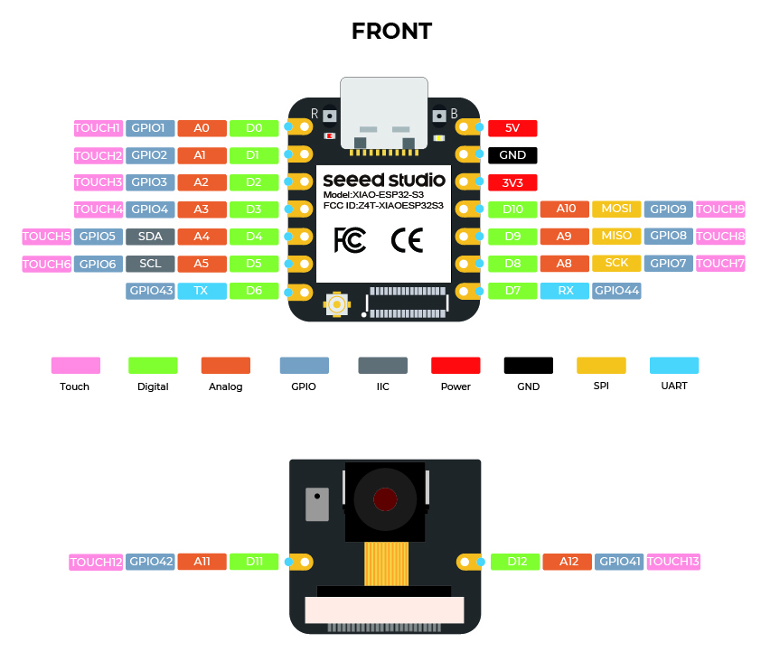
| 标签 | GPIO | 替代功能 |
|---|---|---|
| D0 | 1 | ADC1_CH0 |
| D1 | 2 | ADC1_CH1 |
| D2 | 3 | ADC1_CH2 |
| D3 | 4 | ADC1_CH3 |
| D4 | 5 | ADC1_CH4, SDA |
| D5 | 6 | ADC1_CH5, SCL |
| D6 | 43 | TX |
| D7 | 44 | RX |
| D8 | 7 | ADC1_CH6, SS |
| D9 | 8 | ADC1_CH7, SCK |
| D10 | 9 | ADC1_CH8, MISO |
- GPIO 19 和 20 用于 USB D-/D+,不应重新配置
- GPIO 21 上的板载 LED 是低电平有效(设置为 0 以点亮)
- 所有引脚 D0-D10 都支持通过 ADC1 进行模拟输入
构建和烧录
构建您的项目:
idf.py build
烧录到 XIAO ESP32-S3:
idf.py -p /dev/ttyACM0 flash monitor
将 /dev/ttyACM0 替换为您的实际串口(在 Windows 上,通常是 COM3、COM4 等)。
开发板配置故障排除
PSRAM 未检测到:
- 验证选择了 Octal 模式(不是 Quad)
- 检查 flash 大小是否设置为 8MB
- 确保 ESP-IDF 版本为 4.4 或更高
上传失败:
- 连接 USB 时按住 BOOT 按钮
- 尝试降低上传速度:
idf.py -p PORT -b 115200 flash
引脚冲突:
- 避免使用 GPIO 引脚 19 和 20(USB D- 和 D+)
- XIAO_LED(GPIO 21)与板载 LED 共享
什么是任务?
任务是处理器被要求执行的小功能/作业,具有一组设置。任务可以从小功能到无限循环功能。 任务是 ESP-IDF 应用程序中执行的基本单元。它们本质上是与其他任务并发运行的函数。这允许高效的多任务处理和响应性。
什么是任务属性?
由于这个主题的广泛性,我将只涵盖我们在本指南中将使用的一些属性。
- TaskFunction:这是包含任务实际逻辑的函数。它是任务执行的入口点。
- StackSize:这指定为任务堆栈分配的内存量。堆栈用于存储局部变量、函数返回地址和临时数据。
- TaskPriority:这决定了任务相对于其他任务的重要性。高优先级任务比低优先级任务有更大的机会被优先执行。
- TaskParameters:这些是可选参数,可以在创建任务时传递给任务函数。它们可以用于为任务提供额外的上下文或配置。
- CoreAffinity:这指定任务应该分配给哪个 CPU 核心。在具有多个核心的系统中,这可以用于优化性能或平衡工作负载。
创建任务
要在 FreeRTOS 中创建任务,使用 xTaskCreate 函数。此函数接受多个参数,包括任务函数、任务名称、堆栈大小、参数、优先级和创建任务的句柄。
TaskHandle_t task;
xTaskCreate(
        taskFunction,             /* Function that implements the task. */
        "taskName",               /* Text name for the task. */
        configMINIMAL_STACK_SIZE, /* Stack size in words, or bytes. */
        NULL,                     /* Parameter passed into the task. */
        tskIDLE_PRIORITY,         /* Priority at which the task is created. */
        &task                     /* Used to pass out the created task's handle. */
        );
创建固定到核心的任务
要创建任务并将其固定到特定核心(仅当使用的芯片是双核时),使用 xTaskCreatePinnedToCore 函数。此函数类似于 xTaskCreate,但包含一个用于指定核心的附加参数。
TaskHandle_t task;
xTaskCreatePinnedToCore(
        taskFunction,             /* Function that implements the task. */
        "taskName",               /* Text name for the task. */
        configMINIMAL_STACK_SIZE, /* Stack size in words, or bytes. */
        NULL,                     /* Parameter passed into the task. */
        tskIDLE_PRIORITY,         /* Priority at which the task is created. */
        &task,                    /* Used to pass out the created task's handle. */
        0);                       /* Core ID */
任务函数调用
任务函数是将由任务执行的实际代码。
void taskFunction(void * pvParameters) {
  /*
  Function definition goes here
  */
}
任务的可视化
我正在创建四个简单的任务来可视化 FreeRTOS 的工作原理。
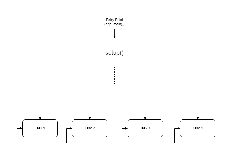
可视化表示
CPU0
-----
taskFunction1 (1000ms delay)

CPU1
-----
taskFunction2 (500ms delay)
taskFunction3 (500ms delay)
taskFunction4 (500ms delay)
代码
#include <stdio.h>
#include "freertos/FreeRTOS.h"
#include "freertos/task.h"
#include "sdkconfig.h"
#include "esp_log.h"

TaskHandle_t task1,task2,task3,task4;

void taskFunction1(void * pvParameters) {
    while (true) {
        ESP_LOGI("Task1", "Hello from task 1");
        vTaskDelay(pdMS_TO_TICKS(1000)); // Add a delay to avoid overwhelming the output
    }
}

void taskFunction2(void * pvParameters) {
    while (true) {
        ESP_LOGI("Task2", "Hello from task 2");
        vTaskDelay(pdMS_TO_TICKS(500)); // Add a delay to avoid overwhelming the output
    }
}

void taskFunction3(void * pvParameters) {
    while (true) {
        ESP_LOGI("Task3", "Hello from task 3");
        vTaskDelay(pdMS_TO_TICKS(500)); // Add a delay to avoid overwhelming the output
    }
}

void taskFunction4(void * pvParameters) {
    while (true) {
        ESP_LOGI("Task4", "Hello from task 4");
        vTaskDelay(pdMS_TO_TICKS(500)); // Add a delay to avoid overwhelming the output
    }
}

void app_main(void) {
    xTaskCreatePinnedToCore(
        taskFunction1, /* Function that implements the task. */
        "task_1",        /* Text name for the task. */
        configMINIMAL_STACK_SIZE, /* Stack size in words, not bytes. */
        NULL,            /* Parameter passed into the task. */
        tskIDLE_PRIORITY, /* Priority at which the task is created. */
        &task1,         /* Used to pass out the created task's handle. */
        0);              /* Core ID */

    xTaskCreatePinnedToCore(
        taskFunction2, /* Function that implements the task. */
        "task_2",        /* Text name for the task. */
        configMINIMAL_STACK_SIZE, /* Stack size in words, not bytes. */
        NULL,            /* Parameter passed into the task. */
        tskIDLE_PRIORITY, /* Priority at which the task is created. */
        &task2,         /* Used to pass out the created task's handle. */
        1);              /* Core ID */

    xTaskCreatePinnedToCore(
        taskFunction3, /* Function that implements the task. */
        "task_3",        /* Text name for the task. */
        configMINIMAL_STACK_SIZE, /* Stack size in words, not bytes. */
        NULL,            /* Parameter passed into the task. */
        tskIDLE_PRIORITY, /* Priority at which the task is created. */
        &task3,         /* Used to pass out the created task's handle. */
        1);              /* Core ID */

    xTaskCreatePinnedToCore(
        taskFunction4, /* Function that implements the task. */
        "task_4",        /* Text name for the task. */
        configMINIMAL_STACK_SIZE, /* Stack size in words, not bytes. */
        NULL,            /* Parameter passed into the task. */
        tskIDLE_PRIORITY, /* Priority at which the task is created. */
        &task4,         /* Used to pass out the created task's handle. */
        1);              /* Core ID */
}
configMINIMAL_STACK_SIZE 可以在 sdkconfig 中更改。
- 四个任务:代码定义了四个任务:taskFunction1、taskFunction2、taskFunction3 和 taskFunction4。
- 任务优先级:所有任务都使用 tskIDLE_PRIORITY 创建。这意味着它们具有相同的优先级。
- 任务固定:taskFunction1 固定到 CPU0,而其他三个任务固定到 CPU1。
- 任务延迟:taskFunction1 有 1000ms 的延迟,而其他三个有 500ms 的延迟。
创建 CPU0 和 CPU1 任务调度
我为 CPU0 和 CPU1 创建了一个基本的任务调度。
CPU0 任务调度
Task: taskFunction1
Priority: Idle (lowest)
Delay: 1000ms
Core: 0
CPU1 任务调度
Tasks: taskFunction2, taskFunction3, taskFunction4
Priorities: All Idle (same priority)
Delays: 500ms for all tasks
Core: 1
这是一个简化的调度。实时系统中的实际任务调度将涉及更复杂的因素,如任务优先级、截止时间和资源约束。
输出
I (11412) Task1: Hello from task 1
I (11522) Task3: Hello from task 3
I (11522) Task2: Hello from task 2
I (11532) Task4: Hello from task 4
I (12032) Task3: Hello from task 3
I (12032) Task2: Hello from task 2
I (12042) Task4: Hello from task 4
I (12422) Task1: Hello from task 1
I (12542) Task3: Hello from task 3
I (12542) Task2: Hello from task 2
I (12552) Task4: Hello from task 4
I (13052) Task3: Hello from task 3
I (13052) Task2: Hello from task 2
I (13062) Task4: Hello from task 4
I (13432) Task1: Hello from task 1
I (13562) Task3: Hello from task 3
I (13562) Task2: Hello from task 2
I (13572) Task4: Hello from task 4
I (14072) Task3: Hello from task 3
I (14072) Task2: Hello from task 2
I (14082) Task4: Hello from task 4
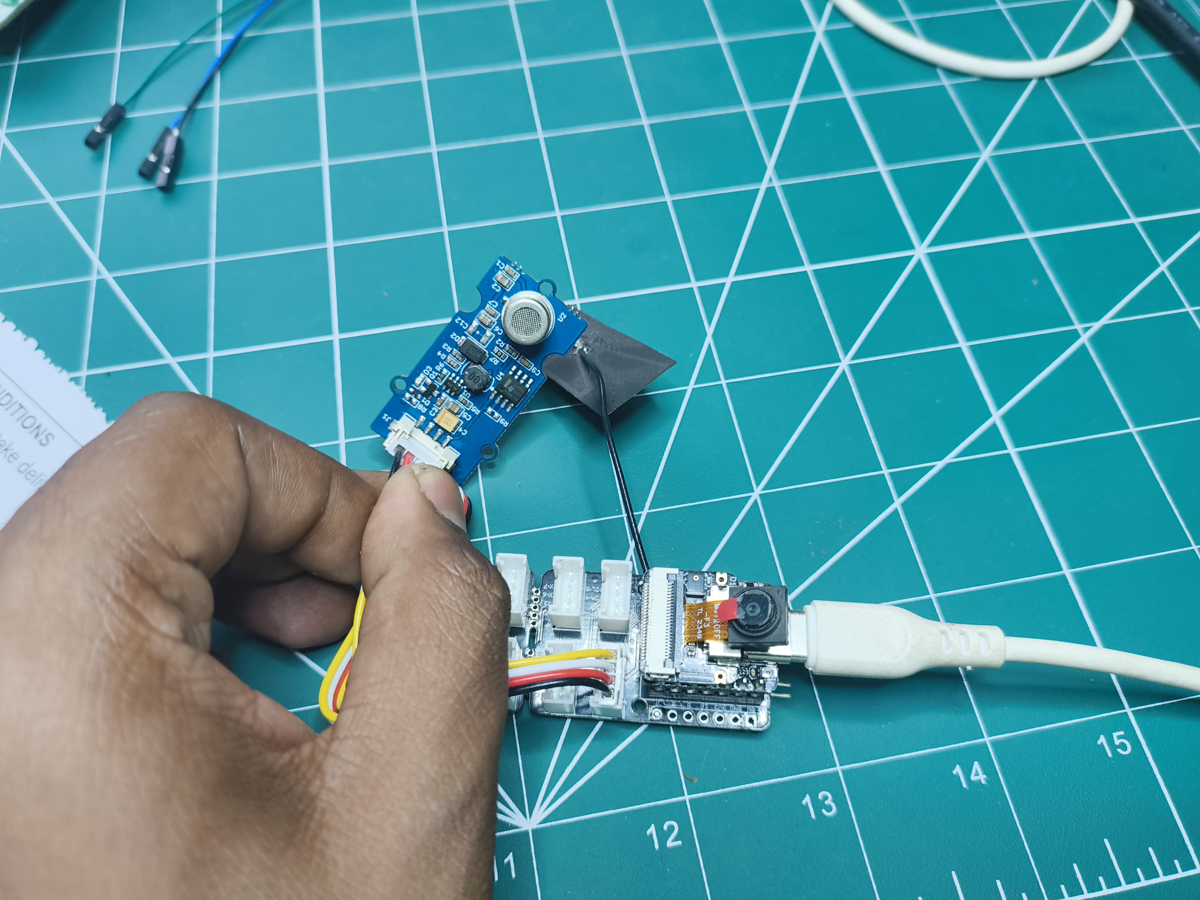
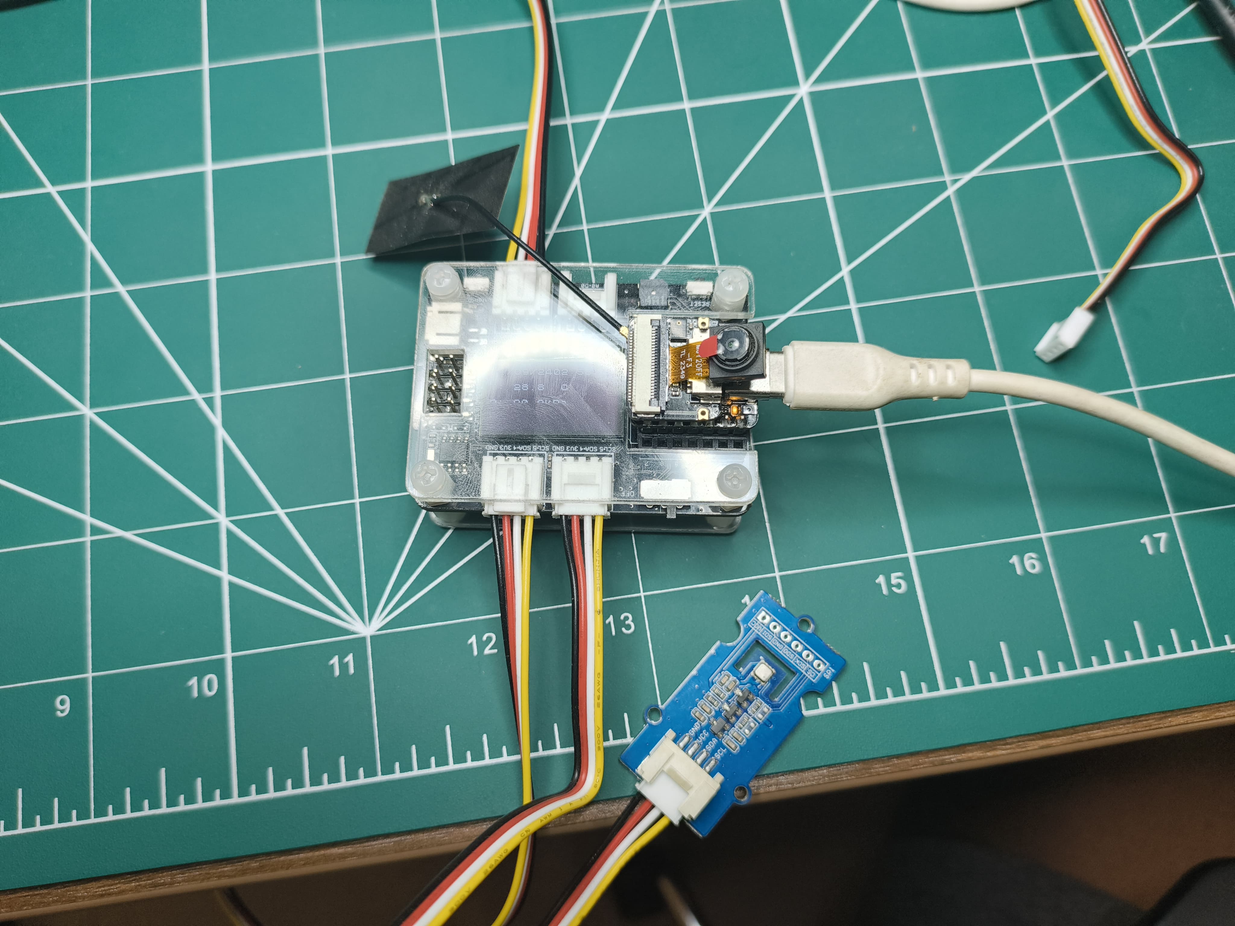
使用 FreeRTOS 进行传感器轮询
为此,我使用了一个模拟传感器 Air Quality Sensor v1.3 以及 ESP_IDF_v5.3。
硬件设置
将 Xiao-S3 连接到 Grove - Expansion Board,并将 Air Quality Sensor v1.3 连接到模拟连接器。
软件设置
拉取 git 仓库后,在 VSCode 中打开文件夹。转到 View->Command Palette->ESP-IDF: Add vscode Configuration Folder。 从底部面板选择正确的 COM 端口、芯片(ESP-S3)并构建、烧录和监控。
代码概述
此代码旨在从传感器收集空气质量数据,处理原始数据以确定空气质量水平,并定期将结果打印到控制台。
关键组件
- 传感器初始化:
air_quality_sensor_t air_quality_sensor;

void sensor_setup()
{
    air_quality_sensor._io_num = ADC_CHANNEL_0;
    air_quality_sensor._adc_num = ADC_UNIT_1;
    printf("Starting Air Quality Sensor...\n");
    if(!initialize_air_quality_sensor(&air_quality_sensor))
    {
        printf("Sensor ready.\n");
    }
    else{
        printf("Sensor ERROR!\n");
    }
}
-
sensor_setup() 函数配置传感器的 I/O 引脚和 ADC 单元。
-
它尝试使用 initialize_air_quality_sensor() 初始化传感器。
-
如果初始化成功,传感器就准备好进行数据收集。
-
数据收集任务:
void poll_read_air_quality_sensor(void *pvParameters)
{
    for (;;)
    {
        air_quality_sensor_slope(&air_quality_sensor);
        vTaskDelay(500 / portTICK_PERIOD_MS);
    }
}
-
poll_read_air_quality_sensor() 任务被创建来持续从传感器读取原始数据。
-
它调用 air_quality_sensor_slope() 来处理原始数据并计算斜率,这是空气质量的指标。
-
任务在读取下一个数据点之前延迟 500 毫秒。
-
数据打印任务:
void print_read_air_quality_sensor(void *pvParameters)
{
    for (;;)
    {
        char buf[40];
        air_quality_error_to_message(air_quality_sensor._air_quality,buf);
        printf("Time : %lu\tSlope : %d\tRaw Value : %d\n%s\n", (uint32_t)esp_timer_get_time() / 1000, air_quality_sensor._air_quality, air_quality_sensor._sensor_raw_value,buf);
        vTaskDelay(1000 / portTICK_PERIOD_MS);
    }
}
- print_read_air_quality_sensor() 任务被创建来定期打印收集的数据和计算的空气质量。
- 它使用 air_quality_error_to_message() 检索当前时间、斜率、原始值和空气质量消息。
- 任务以格式化的方式将数据打印到控制台。
- 任务在打印下一个数据点之前延迟 1000 毫秒。
void app_main(void)
{
    sensor_setup();
    xTaskCreatePinnedToCore(
        poll_read_air_quality_sensor,   /* Function that implements the task. */
        "poll_read_air_quality_sensor", /* Text name for the task. */
        configMINIMAL_STACK_SIZE * 2,   /* Stack size in words, not bytes. */
        NULL,                           /* Parameter passed into the task. */
        tskIDLE_PRIORITY,               /* Priority at which the task is created. */
        NULL,                           /* Used to pass out the created task's handle. */
        0);                             /* Core ID */

    xTaskCreatePinnedToCore(
        print_read_air_quality_sensor,   /* Function that implements the task. */
        "print_read_air_quality_sensor", /* Text name for the task. */
        configMINIMAL_STACK_SIZE * 2,    /* Stack size in words, not bytes. */
        NULL,                            /* Parameter passed into the task. */
        tskIDLE_PRIORITY + 1,            /* Priority at which the task is created. */
        NULL,                            /* Used to pass out the created task's handle. */
        0);                              /* Core ID */
}
输出
Time : 37207    Slope : 3       Raw Value : 273
Fresh air.
Time : 38217    Slope : 3       Raw Value : 269
Fresh air.
Time : 39227    Slope : 3       Raw Value : 274
Fresh air.
Time : 40237    Slope : 3       Raw Value : 251
Fresh air.
Time : 41247    Slope : 3       Raw Value : 276
Fresh air.
Time : 42257    Slope : 3       Raw Value : 250
Fresh air.
Time : 43267    Slope : 3       Raw Value : 236
Fresh air.
Time : 44277    Slope : 3       Raw Value : 253
Fresh air.
Time : 45287    Slope : 3       Raw Value : 245
Fresh air.
Time : 46297    Slope : 3       Raw Value : 249
Fresh air.
Time : 47307    Slope : 3       Raw Value : 244
Fresh air.
Time : 48317    Slope : 3       Raw Value : 235
Fresh air.
Time : 49327    Slope : 3       Raw Value : 239
Fresh air.
Time : 50337    Slope : 3       Raw Value : 233
Fresh air.
Time : 51347    Slope : 3       Raw Value : 235
Fresh air.
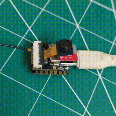
在 FreeRTOS 中使用摄像头和 SD 卡
为此,我使用板载摄像头和 SD 卡以及 ESP_IDF_v5.3。
硬件设置
按照 microSD 卡指南 和 摄像头指南 将摄像头和 microSD 卡扩展板连接到
- 格式化 microSD 卡(支持最大 32GB)
- 将 microSD 卡连接到扩展板
设置看起来像这样:
| 正面 | 背面 |
|---|---|
 |  |
软件设置
拉取 git 仓库后,在 VSCode 中打开文件夹。转到 View->Command Palette->ESP-IDF: Add vscode Configuration Folder。 从底部面板选择正确的 COM 端口、芯片(ESP-S3)并构建、烧录和监控。
如果您使用的是 OV3660 型号,您需要在 IDF 中设置它以便能够驱动它。在终端中输入 "idf.py menuconfig"
| 步骤 1 | 步骤 2 | 步骤 3 |
|---|---|---|
 |  |  |
摄像头组件
- 摄像头配置:
- 定义用于各种摄像头功能的 GPIO 引脚(PWDN、RESET、XCLK、SIOD、SIOC、Y9-Y2、VSYNC、HREF、PCLK、LED)。
- 设置摄像头参数的默认值(例如时钟频率、帧缓冲区位置、像素格式、帧大小、JPEG 质量、帧缓冲区数量、抓取模式)。
#ifndef CAMERA_CONFIG_H
#define CAMERA_CONFIG_H

#define PWDN_GPIO_NUM     -1
#define RESET_GPIO_NUM    -1
#define XCLK_GPIO_NUM     10
#define SIOD_GPIO_NUM     40
#define SIOC_GPIO_NUM     39

#define Y9_GPIO_NUM       48
#define Y8_GPIO_NUM       11
#define Y7_GPIO_NUM       12
#define Y6_GPIO_NUM       14
#define Y5_GPIO_NUM       16
#define Y4_GPIO_NUM       18
#define Y3_GPIO_NUM       17
#define Y2_GPIO_NUM       15
#define VSYNC_GPIO_NUM    38
#define HREF_GPIO_NUM     47
#define PCLK_GPIO_NUM     13

#define LED_GPIO_NUM      21

#endif //CAMERA_CONFIG_H
-
摄像头接口:
声明函数 initialize_camera() 和 createCameraTask()。 -
摄像头实现:
- 使用定义的配置初始化摄像头。
void initialize_camera(void)
{
  camera_config_t camera_config = {
      .pin_pwdn = PWDN_GPIO_NUM,
      .pin_reset = RESET_GPIO_NUM,
      .pin_xclk = XCLK_GPIO_NUM,
      .pin_sccb_sda = SIOD_GPIO_NUM,
      .pin_sccb_scl = SIOC_GPIO_NUM,
      .pin_d7 = Y9_GPIO_NUM,
      .pin_d6 = Y8_GPIO_NUM,
      .pin_d5 = Y7_GPIO_NUM,
      .pin_d4 = Y6_GPIO_NUM,
      .pin_d3 = Y5_GPIO_NUM,
      .pin_d2 = Y4_GPIO_NUM,
      .pin_d1 = Y3_GPIO_NUM,
      .pin_d0 = Y2_GPIO_NUM,
      .pin_vsync = VSYNC_GPIO_NUM,
      .pin_href = HREF_GPIO_NUM,
      .pin_pclk = PCLK_GPIO_NUM,

      .xclk_freq_hz = 20000000,          // The clock frequency of the image sensor
      .fb_location = CAMERA_FB_IN_PSRAM, // Set the frame buffer storage location
      .pixel_format = PIXFORMAT_JPEG,    // The pixel format of the image: PIXFORMAT_ + YUV422|GRAYSCALE|RGB565|JPEG
      .frame_size = FRAMESIZE_UXGA,      // The resolution size of the image: FRAMESIZE_ + QVGA|CIF|VGA|SVGA|XGA|SXGA|UXGA
      .jpeg_quality = 15,                // The quality of the JPEG image, ranging from 0 to 63.
      .fb_count = 2,                     // The number of frame buffers to use.
      .grab_mode = CAMERA_GRAB_LATEST    //  The image capture mode.
  };

  esp_err_t ret = esp_camera_init(&camera_config);
  if (ret == ESP_OK)
  {
      ESP_LOGI(cameraTag, "Camera configured successful");
  }
  else
  {
      ESP_LOGI(cameraTag, "Camera configured unsuccessful");
      return;
  }
}- 设置摄像头参数(亮度、对比度、饱和度、特殊效果、白平衡、曝光控制、AEC、AE 级别、AEC 值、增益控制、AGC 增益、增益上限、BPC、WPC、原始 GMA、LENC、水平镜像、垂直翻转、DCW、彩条)。
sensor_t *s = esp_camera_sensor_get();

  s->set_brightness(s, 0);                 // -2 to 2
  s->set_contrast(s, 0);                   // -2 to 2
  s->set_saturation(s, 0);                 // -2 to 2
  s->set_special_effect(s, 0);             // 0 to 6 (0 - No Effect, 1 - Negative, 2 - Grayscale, 3 - Red Tint, 4 - Green Tint, 5 - Blue Tint, 6 - Sepia)
  s->set_whitebal(s, 1);                   // 0 = disable , 1 = enable
  s->set_awb_gain(s, 1);                   // 0 = disable , 1 = enable
  s->set_wb_mode(s, 0);                    // 0 to 4 - if awb_gain enabled (0 - Auto, 1 - Sunny, 2 - Cloudy, 3 - Office, 4 - Home)
  s->set_exposure_ctrl(s, 1);              // 0 = disable , 1 = enable
  s->set_aec2(s, 0);                       // 0 = disable , 1 = enable
  s->set_ae_level(s, 0);                   // -2 to 2
  s->set_aec_value(s, 300);                // 0 to 1200
  s->set_gain_ctrl(s, 1);                  // 0 = disable , 1 = enable
  s->set_agc_gain(s, 0);                   // 0 to 30
  s->set_gainceiling(s, (gainceiling_t)0); // 0 to 6
  s->set_bpc(s, 0);                        // 0 = disable , 1 = enable
  s->set_wpc(s, 1);                        // 0 = disable , 1 = enable
  s->set_raw_gma(s, 1);                    // 0 = disable , 1 = enable
  s->set_lenc(s, 1);                       // 0 = disable , 1 = enable
  s->set_hmirror(s, 0);                    // 0 = disable , 1 = enable
  s->set_vflip(s, 0);                      // 0 = disable , 1 = enable
  s->set_dcw(s, 1);                        // 0 = disable , 1 = enable
s->set_colorbar(s, 0); // 0 = disable , 1 = enable- 定义一个 takePicture() 函数来捕获图像并将其保存到 SD 卡。
void takePicture()
{
  ESP_LOGI(cameraTag, "Taking picture...");
  camera_fb_t *pic = esp_camera_fb_get();

  if (pic)
  {
      saveJpegToSdcard(pic);
  }

  ESP_LOGI(cameraTag, "Picture taken! Its size was: %zu bytes", pic->len);

  esp_camera_fb_return(pic);
}- 创建一个任务 cameraTakePicture_5_sec() 来每 5 秒连续拍照。
void cameraTakePicture_5_sec(void *pvParameters)
{
    for (;;)
    {
        takePicture();
        vTaskDelay(5000 / portTICK_PERIOD_MS);
    }
}

void createCameraTask()
{
    TaskHandle_t task;
    xTaskCreate(
        cameraTakePicture_5_sec,      /* Function that implements the task. */
        "cameraTakePicture_5_sec",    /* Text name for the task. */
        configMINIMAL_STACK_SIZE * 4, /* Stack size in words, or bytes. */
        NULL,                         /* Parameter passed into the task. */
        tskIDLE_PRIORITY,             /* Priority at which the task is created. */
        &task                         /* Used to pass out the created task's handle. */
    );
}
代码结构:
- 头文件(camera_config.h、camera_interface.h)和实现文件(camera_interface.c)。
- camera_config.h 文件定义摄像头配置参数。
- camera_interface.h 文件声明摄像头初始化和任务创建的函数。
- camera_interface.c 文件实现摄像头初始化、拍照和任务创建逻辑。
SD 卡组件
- SD 卡配置:
定义用于 SD 卡接口的 GPIO 引脚(MISO、MOSI、CLK、CS)。
#ifndef SDCARD_CONFIG_H
#define SDCARD_CONFIG_H

#define PIN_NUM_MISO  GPIO_NUM_8
#define PIN_NUM_MOSI  GPIO_NUM_9
#define PIN_NUM_CLK   GPIO_NUM_7
#define PIN_NUM_CS    GPIO_NUM_21

#endif //SDCARD_CONFIG_H
- SD 卡接口:
声明函数 initialize_sdcard()、deinitialize_sdcard() 和 saveJpegToSdcard()。
#ifndef SDCARD_INTERFACE_H
#define SDCARD_INTERFACE_H

#include "esp_camera.h"

void initialize_sdcard(void);
void deinitialize_sdcard();
void saveJpegToSdcard(camera_fb_t *);

#endif //SDCARD_INTERFACE_H
-
SD 卡实现:
- 使用定义的配置初始化 SD 卡,并将 SD 卡挂载为 FAT 文件系统。
sdmmc_card_t *card;
sdmmc_host_t host = SDSPI_HOST_DEFAULT();
const char mount_point[] = "/sd";

void initialize_sdcard()
{
    esp_err_t ret;

    // If format_if_mount_failed is set to true, SD card will be partitioned and
    // formatted in case when mounting fails.
    esp_vfs_fat_sdmmc_mount_config_t mount_config = {
#ifdef FORMAT_IF_MOUNT_FAILED
        .format_if_mount_failed = true,
#else
        .format_if_mount_failed = false,
#endif // EXAMPLE_FORMAT_IF_MOUNT_FAILED
        .max_files = 5,
        .allocation_unit_size = 32 * 1024};

    ESP_LOGI(sdcardTag, "Initializing SD card");

    // Use settings defined above to initialize SD card and mount FAT filesystem.
    // Note: esp_vfs_fat_sdmmc/sdspi_mount is all-in-one convenience functions.
    // Please check its source code and implement error recovery when developing
    // production applications.
    ESP_LOGI(sdcardTag, "Using SPI peripheral");

    // By default, SD card frequency is initialized to SDMMC_FREQ_DEFAULT (20MHz)
    // For setting a specific frequency, use host.max_freq_khz (range 400kHz - 20MHz for SDSPI)
    spi_bus_config_t bus_cfg = {
        .mosi_io_num = PIN_NUM_MOSI,
        .miso_io_num = PIN_NUM_MISO,
        .sclk_io_num = PIN_NUM_CLK,
        .quadwp_io_num = -1,
        .quadhd_io_num = -1,
        .max_transfer_sz = host.max_freq_khz,
    };
    ret = spi_bus_initialize(host.slot, &bus_cfg, SDSPI_DEFAULT_DMA);
    if (ret != ESP_OK)
    {
        ESP_LOGE(sdcardTag, "Failed to initialize bus.");
        return;
    }

    // This initializes the slot without card detect (CD) and write protect (WP) signals.
    // Modify slot_config.gpio_cd and slot_config.gpio_wp if your board has these signals.
    sdspi_device_config_t slot_config = SDSPI_DEVICE_CONFIG_DEFAULT();
    slot_config.gpio_cs = PIN_NUM_CS;
    slot_config.host_id = host.slot;

    ESP_LOGI(sdcardTag, "Mounting filesystem");
    ret = esp_vfs_fat_sdspi_mount(mount_point, &host, &slot_config, &mount_config, &card);

    if (ret != ESP_OK)
    {
        if (ret == ESP_FAIL)
        {
            ESP_LOGE(sdcardTag, "Failed to mount filesystem. "
                                "If you want the card to be formatted, set the FORMAT_IF_MOUNT_FAILED in sdcard_config.h");
        }
        else
        {
            ESP_LOGE(sdcardTag, "Failed to initialize the card (%s). "
                                "Make sure SD card lines have pull-up resistors in place.",
                    esp_err_to_name(ret));
        }
        return;
    }
    ESP_LOGI(sdcardTag, "Filesystem mounted");

    // Card has been initialized, print its properties
    sdmmc_card_print_info(stdout, card);

    // Format FATFS
#ifdef FORMAT_SD_CARD
    ret = esp_vfs_fat_sdcard_format(mount_point, card);
    if (ret != ESP_OK)
    {
        ESP_LOGE(sdcardTag, "Failed to format FATFS (%s)", esp_err_to_name(ret));
        return;
    }

    if (stat(file_foo, &st) == 0)
    {
        ESP_LOGI(sdcardTag, "file still exists");
        return;
    }
    else
    {
        ESP_LOGI(sdcardTag, "file doesnt exist, format done");
    }
#endif // CONFIG_EXAMPLE_FORMAT_SD_CARD
}- 提供将 JPEG 图像保存到 SD 卡的函数。
uint16_t lastKnownFile = 0;

void saveJpegToSdcard(camera_fb_t *captureImage)
{
  // Find the next available filename
  char filename[32];

  sprintf(filename, "%s/%u_img.jpg", mount_point, lastKnownFile++);

  // Create the file and write the JPEG data
  FILE *fp = fopen(filename, "wb");
  if (fp != NULL)
  {
      fwrite(captureImage->buf, 1, captureImage->len, fp);
      fclose(fp);
      ESP_LOGI(sdcardTag, "JPEG saved as %s", filename);
  }
  else
  {
      ESP_LOGE(sdcardTag, "Failed to create file: %s", filename);
  }
}
组件结构:
- 头文件(sdcard_config.h、sdcard_interface.h)和实现文件(sdcard_interface.c)。
- sdcard_config.h 文件定义 SD 卡配置参数。
- sdcard_interface.h 文件声明 SD 卡初始化、去初始化和图像保存的函数。
- sdcard_interface.c 文件实现 SD 卡初始化、去初始化和图像保存逻辑。
主函数
// main.c
#include <stdio.h>
#include "camera_interface.h"
#include "sdcard_interface.h"

void initialize_drivers()
{
    initialize_sdcard();
    initialize_camera();
}

void start_tasks()
{
    createCameraTask();
}

void app_main(void)
{
    initialize_drivers();
    start_tasks();
}
- 包含摄像头和 SD 卡接口所需的头文件。
- 使用提供的函数初始化 SD 卡和摄像头。
- 启动摄像头任务以连续拍照
输出
UART 输出
I (1119) main_task: Calling app_main()
I (1123) sdcard: Initializing SD card
I (1127) sdcard: Using SPI peripheral
I (1132) sdcard: Mounting filesystem
I (1137) gpio: GPIO[21]| InputEn: 0| OutputEn: 1| OpenDrain: 0| Pullup: 0| Pulldown: 0| Intr:0
I (1146) sdspi_transaction: cmd=52, R1 response: command not supported
I (1195) sdspi_transaction: cmd=5, R1 response: command not supported
I (1219) sdcard: Filesystem mounted
Name: SD32G
Type: SDHC/SDXC
Speed: 20.00 MHz (limit: 20.00 MHz)
Size: 30448MB
CSD: ver=2, sector_size=512, capacity=62357504 read_bl_len=9
SSR: bus_width=1
I (1226) s3 ll_cam: DMA Channel=1
I (1230) cam_hal: cam init ok
I (1234) sccb: pin_sda 40 pin_scl 39
I (1238) sccb: sccb_i2c_port=1
I (1252) camera: Detected camera at address=0x30
I (1255) camera: Detected OV2640 camera
I (1255) camera: Camera PID=0x26 VER=0x42 MIDL=0x7f MIDH=0xa2
I (1344) cam_hal: buffer_size: 16384, half_buffer_size: 1024, node_buffer_size: 1024, node_cnt: 16, total_cnt: 375
I (1344) cam_hal: Allocating 384000 Byte frame buffer in PSRAM
I (1351) cam_hal: Allocating 384000 Byte frame buffer in PSRAM
I (1357) cam_hal: cam config ok
I (1361) ov2640: Set PLL: clk_2x: 0, clk_div: 0, pclk_auto: 0, pclk_div: 12
I (1453) camera: Camera configured successful
I (1487) main_task: Returned from app_main()
I (1487) camera: Taking picture...
I (1997) sdcard: JPEG saved as /sd/0_img.jpg
I (1997) camera: Picture taken! Its size was: 45764 bytes
I (6997) camera: Taking picture...
I (7348) sdcard: JPEG saved as /sd/1_img.jpg
I (7349) camera: Picture taken! Its size was: 51710 bytes
I (12349) camera: Taking picture...
I (12704) sdcard: JPEG saved as /sd/2_img.jpg
I (12705) camera: Picture taken! Its size was: 51853 bytes
I (17706) camera: Taking picture...
I (18054) sdcard: JPEG saved as /sd/3_img.jpg
I (18055) camera: Picture taken! Its size was: 51919 bytes
I (23055) camera: Taking picture...
I (23414) sdcard: JPEG saved as /sd/4_img.jpg
I (23414) camera: Picture taken! Its size was: 51809 bytes
I (28415) camera: Taking picture...
I (28768) sdcard: JPEG saved as /sd/5_img.jpg
I (28768) camera: Picture taken! Its size was: 51747 bytes
I (33771) camera: Taking picture...
I (34117) sdcard: JPEG saved as /sd/6_img.jpg
I (34117) camera: Picture taken! Its size was: 51968 bytes
输出图像
Arduino IDE 的 FreeRtos
FreeRtos 可以用于基于 Arduino-IDE 的 XIAO-S3 构建。它类似于 ESP-IDF 可用,但它只在一个核心上运行,并且没有针对 ESP-IDF 进行优化。
硬件设置
将 Xiao-S3 连接到 Grove - 扩展板(OLED 显示屏和 RTC),并将 Grove - Arduino 温度、湿度、压力和气体传感器 - BME680 连接到 I2c 总线。
软件设置
安装 pcf8563、U8x8lib 和 bme680 库的 Arduino 库。参考如何安装库来为 Arduino 安装库。
#include "time.h"
#include <WiFi.h>
#include <PCF8563.h>
#include <U8x8lib.h>
#include <Wire.h>
#include "seeed_bme680.h"

#define IIC_ADDR uint8_t(0x76)
Seeed_BME680 bme680(IIC_ADDR); /* IIC PROTOCOL */

// I2C communication library for the PCF8563 real-time clock
PCF8563 pcf;

// OLED display library
U8X8_SSD1306_128X64_NONAME_HW_I2C u8x8(/* clock=*/D4, /* data=*/D5, /* reset=*/U8X8_PIN_NONE);  // OLEDs without Reset of the Display

// WiFi network credentials
const char* ssid = "REPLACE_WITH_YOUR_SSID";
const char* password = "REPLACE_WITH_YOUR_PASSWORD";

// NTP server for time synchronization
const char* ntpServer = "pool.ntp.org";

// Timezone offset (adjust based on your location)
const long gmtOffset_sec = 5.5 * 60 * 60;  // Hours * Minutes * Seconds (here, GMT+5:30)
const int daylightOffset_sec = 0;          // No daylight saving time assumed

// Global variable to store current time information
static Time nowTime;

// Function prototypes for tasks
void printDateAndTime(void* pvParameters);
void updateTime(void* pvParameters);
void ledBlink2Hz(void* pvParameters);
void oledDisplayUpdate(void* pvParameters);
void taskBME680(void* pvParameters);

// Setup function (runs once at startup)
void setup() {

  Serial.begin(115200);  // Initialize serial communication for debugging

  // Set built-in LED pin as output for blinking
  pinMode(LED_BUILTIN, OUTPUT);

  Serial.print("Connecting to ");
  Serial.println(ssid);
  WiFi.begin(ssid, password);  // Connect to WiFi network
  while (WiFi.status() != WL_CONNECTED) {
    delay(500);
    Serial.print(".");
  }

  while (!bme680.init()) {
    Serial.println("bme680 init failed ! can't find device!");
    delay(10000);
  }

  pcf.init();  // Initialize the PCF8563 real-time clock

  // Stop the clock before setting the time
  pcf.stopClock();

  // Configure time synchronization using NTP server
  configTime(gmtOffset_sec, daylightOffset_sec, ntpServer);
  static struct tm timeinfo;
  while (!getLocalTime(&timeinfo)) {
    Serial.println("no received time info ... Waiting ...");
  }

  // Set the time on the PCF8563 clock based on retrieved time
  pcf.setYear(timeinfo.tm_year);
  pcf.setMonth(timeinfo.tm_mon);
  pcf.setDay(timeinfo.tm_mday);
  pcf.setHour(timeinfo.tm_hour);
  pcf.setMinut(timeinfo.tm_min);
  pcf.setSecond(timeinfo.tm_sec);

  pcf.startClock();  // Start the clock after setting the time

  Serial.println("WiFi connected at " + WiFi.localIP());

  u8x8.begin();         // Initialize the OLED display
  u8x8.setFlipMode(1);  // Optionally rotate OLED display content

  // Create tasks for different functionalities
  xTaskCreate(
    updateTime,
    "Get LocalTime",
    configMINIMAL_STACK_SIZE * 2,
    (void*)1,
    tskIDLE_PRIORITY + 1,
    NULL);

  xTaskCreate(
    ledBlink2Hz,
    "Task 2",
    configMINIMAL_STACK_SIZE,
    (void*)1,
    tskIDLE_PRIORITY + 1,
    NULL);

  xTaskCreate(
    oledDisplayUpdate,
    "OLED Display Task",
    configMINIMAL_STACK_SIZE * 2,
    (void*)1,
    tskIDLE_PRIORITY,
    NULL);

  xTaskCreate(
    printDateAndTime,
    "Print Uart",
    configMINIMAL_STACK_SIZE * 2,
    (void*)1,
    tskIDLE_PRIORITY,
    NULL);

  xTaskCreate(
    taskBME680,
    "BME680 Sensor Poll",
    configMINIMAL_STACK_SIZE * 2,
    (void*)1,
    tskIDLE_PRIORITY + 1,
    NULL);
}

// Loop function (doesn't do anything in this case, tasks handle everything)
void loop() {
  // Nothing to do here, all work is done in the tasks
}

// Function that will run as a task: Prints current date and time to serial port
void printDateAndTime(void* pvParameters) {
  for (;;) {
    // Print current time in formatted string (DD/MM/YY\tHH:MM:SS) to serial port
    Serial.printf("%02d/%02d/%02d\t%02d:%02d:%02d\n",
                  nowTime.day, nowTime.month + 1, nowTime.year % 100,
                  nowTime.hour, nowTime.minute, nowTime.second);
    // Delay for 1 second before reading time again
    vTaskDelay(1000 / portTICK_PERIOD_MS);
  }
}

// Function that will run as a task: Reads current time from PCF8563 clock
void updateTime(void* pvParameters) {
  for (;;) {
    // Update the global `nowTime` variable with the current time from the PCF8563 clock
    nowTime = pcf.getTime();
    // Delay for 0.5 second before reading time again (can be adjusted for desired update frequency)
    vTaskDelay(500 / portTICK_PERIOD_MS);
  }
}

// Function that will run as a task: Blinks the built-in LED at 2Hz
void ledBlink2Hz(void* pvParameters) {
  bool state = true;  // Initial state for LED (on or off)
  for (;;) {
    // Set LED state (HIGH for on, LOW for off)
    digitalWrite(LED_BUILTIN, (state ? HIGH : LOW));
    // Delay for 0.5 second to create a 2Hz blinking frequency (one cycle on/off)
    vTaskDelay(500 / portTICK_PERIOD_MS);
    // Toggle LED state for the next cycle
    state = !state;
  }
}

// Function that will run as a task: Updates OLED display with date and time
void oledDisplayUpdate(void* pvParameters) {
  for (;;) {

    // Set font for the first line (date)
    u8x8.setFont(u8x8_font_chroma48medium8_r);

    // Set cursor position for the first line (centered)
    u8x8.setCursor(0, 0);

    char buffer1[12];  // Buffer to hold formatted date string
    std::snprintf(buffer1, sizeof(buffer1), "%02d/%02d/%02d",
                  nowTime.day, nowTime.month + 1, nowTime.year % 100);
    u8x8.print(buffer1);

    // Format time string (HH:MM:SS) into buffer2 using std::snprintf
    std::snprintf(buffer1, sizeof(buffer1), "%02d:%02d:%02d",
                  nowTime.hour, nowTime.minute, nowTime.second);
    // Print formatted time string to OLED display
    u8x8.print(buffer1);

    // Adjust cursor position for the second line (below the first line)
    u8x8.setCursor(0, 10);

    char buffer2[20];  // Buffer to hold formatted sensor data

    std::snprintf(buffer2, sizeof(buffer2), "T: %.1f°C", bme680.sensor_result_value.temperature);
    u8x8.print(buffer2);
    u8x8.setCursor(0, 20);

    std::snprintf(buffer2, sizeof(buffer2), "P: %.1fkPa", bme680.sensor_result_value.pressure / 1000.0);
    u8x8.print(buffer2);

    u8x8.setCursor(0, 30);

    std::snprintf(buffer2, sizeof(buffer2), "H: %.1f%%", bme680.sensor_result_value.humidity);
    u8x8.print(buffer2);

    // std::snprintf(buffer2, sizeof(buffer2), "G: %.1f Kohms", bme680.sensor_result_value.gas / 1000.0);
    // u8x8.print(buffer2);

    vTaskDelay(100 / portTICK_PERIOD_MS);  // Update every 0.1 seconds (adjust as needed)
  }
}

void taskBME680(void* pvParameters) {
  for (;;) {
    if (bme680.read_sensor_data()) {
      Serial.println("Failed to perform reading :(");
    } else {
      Serial.print("T: ");
      Serial.print(bme680.sensor_result_value.temperature, 2);
      Serial.print(" C  P: ");
      Serial.print(bme680.sensor_result_value.pressure / 1000.0, 2);
      Serial.print(" KPa  H: ");
      Serial.print(bme680.sensor_result_value.humidity, 2);
      Serial.print(" %  G: ");
      Serial.print(bme680.sensor_result_value.gas / 1000.0, 2);
      Serial.println(" Kohms");
    }

    vTaskDelay(1000 / portTICK_PERIOD_MS);
  }
}
输出
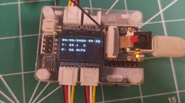
串口监视器输出
09/09/24 03:17:20
T: 29.01 C  P: 90.86 KPa  H: 63.41 %  G: 47.41 Kohms
09/09/24 03:17:21
T: 29.03 C  P: 90.86 KPa  H: 63.34 %  G: 47.85 Kohms
Arduino FreeRtos vs ESP-IDF FreeRtos
| 功能 | Arduino FreeRTOS | ESP-IDF FreeRTOS |
|---|---|---|
| 抽象层 | 更高级别的抽象,对初学者更容易 | 更低级别的抽象,为有经验的用户提供更多控制 |
| 开发环境 | Arduino IDE | ESP-IDF 命令行工具 |
| 兼容性 | 主要与基于 Arduino 的开发板兼容 | 与更广泛的 ESP32 和 ESP32-S2 开发板兼容 |
| 功能 | 基本 RTOS 功能、任务创建、调度、同步 | 全面的 RTOS 功能、任务创建、调度、同步、事件组、队列、互斥锁、信号量 |
| 性能 | 由于抽象层,性能通常较低 | 由于直接访问硬件和 RTOS API,性能更高 |
| 定制 | 定制选项有限 | 通过配置文件和 API 提供广泛的定制选项 |
| 学习曲线 | 对初学者更容易学习 | 对于不熟悉命令行工具和 C/C++ 的人来说学习曲线更陡峭 |
| 使用场景 | 简单的物联网项目、原型制作 | 复杂的物联网应用、实时系统、定制硬件 |
故障排除
在硬件连接、软件调试或上传过程中可能会遇到一些问题。
技术支持与产品讨论
感谢您选择我们的产品!我们在这里为您提供不同的支持,以确保您使用我们产品的体验尽可能顺畅。我们提供多种沟通渠道,以满足不同的偏好和需求。