Seeed Studio XIAO RP2350 与 C/C++ SDK
介绍
Seeed Studio XIAO RP2350 由 RP2350 微控制器驱动,在小巧的外形尺寸中提供强大的性能。本指南提供了在 XIAO RP2350 上设置和使用 C/C++ SDK 的基本步骤。
先决条件
开始之前,请确保您具备以下条件:
- 一台运行 Windows、macOS 或 Linux 的计算机。
- 一根 USB 线缆,用于将 XIAO RP2350 连接到您的计算机。
- C/C++ 编程的基础知识。
通过 VSCode 安装指南
对于那些偏好原生开发体验的用户,请探索 Raspberry Pi Pico C/C++ SDK 文档 或 Raspberry Pi Pico SDK | GitHub。
为了获得更简单、更流畅的 SDK 编程体验,特别是对于 SDK 编程新手,您可以为 Visual Studio Code (VSCode) 安装 Raspberry Pi Pico 扩展。
此扩展通过引导您完成必要的工具链安装来简化设置过程,避免了手动逐个安装每个工具的需要。但是,您仍需要确保您的系统满足平台要求:Windows x64、macOS(Sonoma 及更新版本)、Linux x64 或 arm64。
有关针对您的操作系统的详细安装说明,请参考 VSCode 的 Raspberry Pi Pico 扩展 页面。
步骤 1:安装扩展
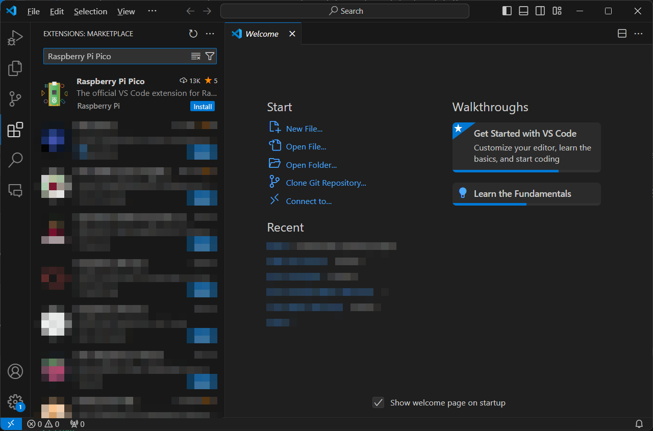
步骤 2:创建新项目
页面加载完成后,您可以看到所需的内容。
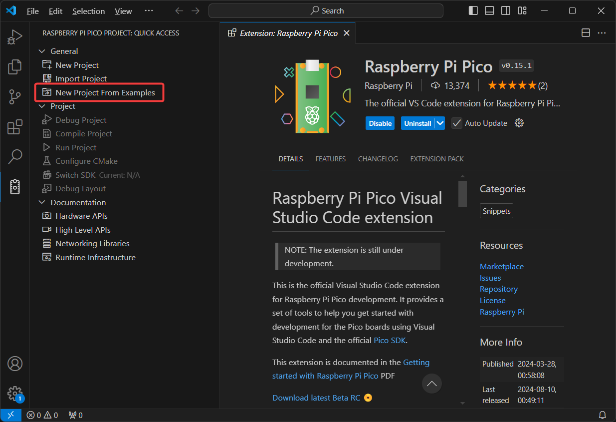
尝试通过 New Project From Examples 创建项目。
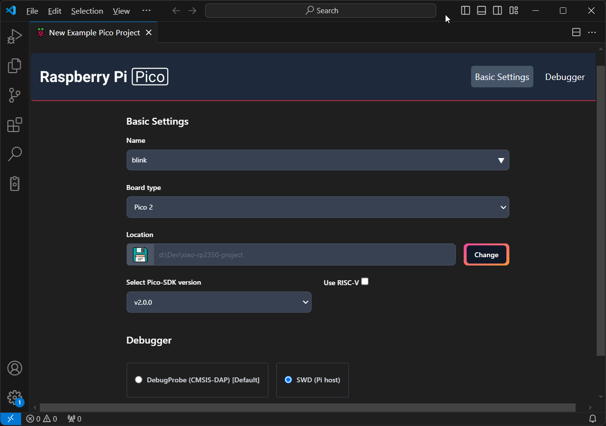
步骤 3:配置您的项目
- 名称: 通常,这将是示例项目名称;在这种情况下,我们将选择
blink项目。 - 板类型:
Pico 2 - 位置: 选择您想要存储 XIAO RP2350 项目的位置。
- SDK 版本: 必须是
v2.0.0或更高版本。 - 调试器: 如果您计划使用 SWD 调试接口,请勾选 SWD 调试器选项以便稍后启用调试。
- 配置项目
- 高级选项
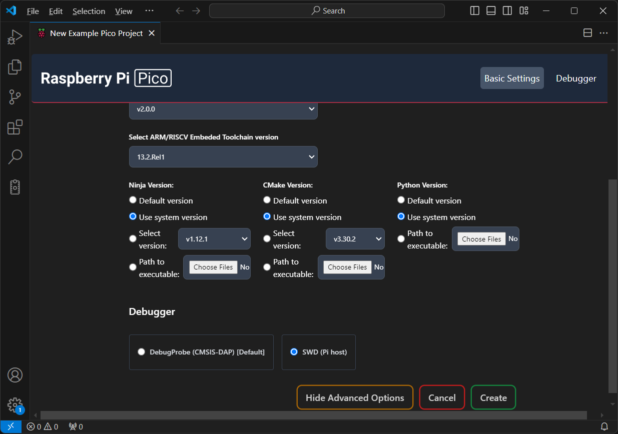
如果您想要微调工具链设置并避免下载冗余资源,请勾选 高级选项。在这里,您可以指定 Ninja 和 CMake 等工具的路径。如果您之前没有安装 CMake 或 Python 环境,或者您不想担心这个问题,可以跳过此步骤。
在此示例中,我将使用已安装在我的 Windows 机器上并添加到系统 PATH 的系统版本。因此,我选择 使用系统版本。
如果这是您第一次运行设置,当您点击 Create 时,扩展将为您下载和管理 SDK。在 Windows 上,SDK 通常会放置在 %userprofile%.pico-sdk 中。设置所需的时间取决于您的网络速度。完成后,将打开一个包含您项目的新窗口。
步骤 4:构建项目
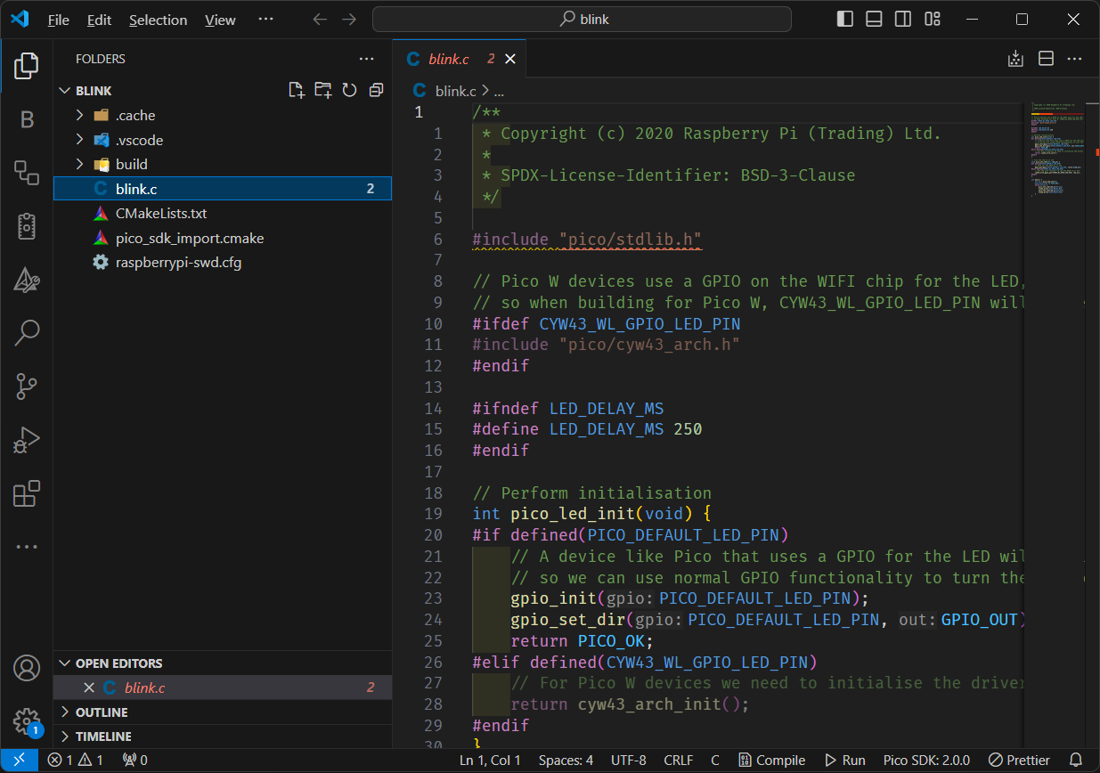
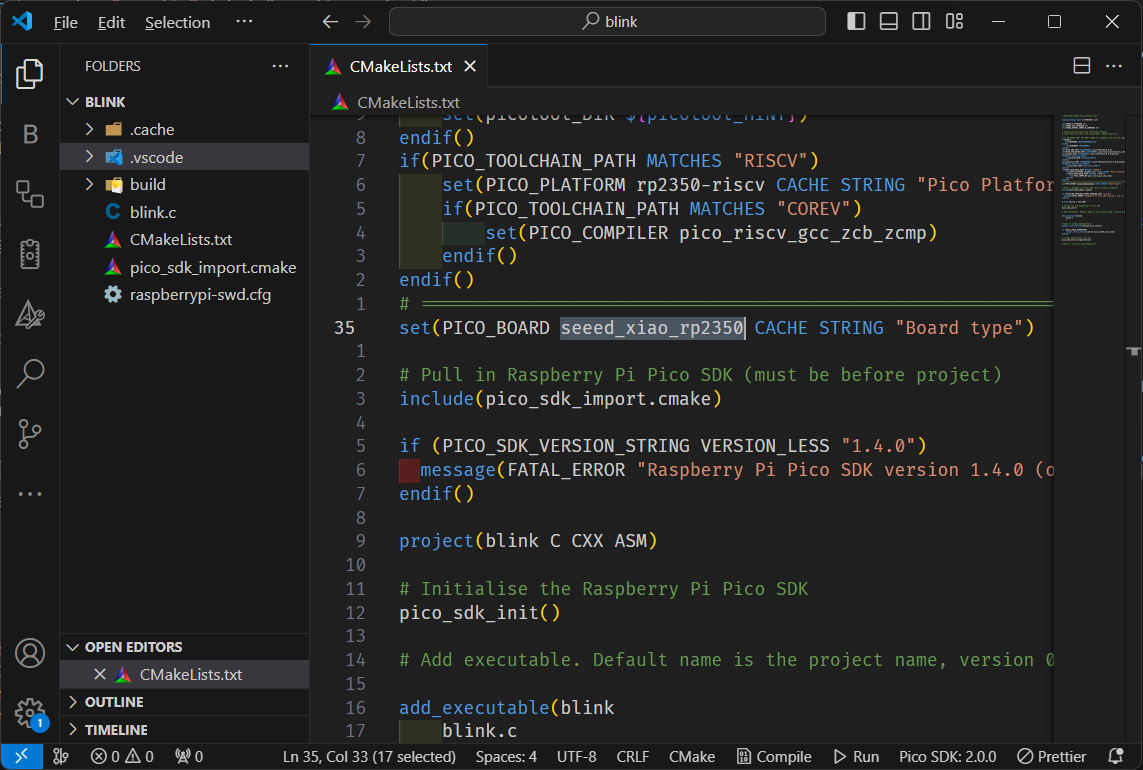
第一次设置项目时,您需要手动修改 CMake 项目中的板类型,因为扩展默认不包含 XIAO RP2350 板。将板设置为 seeed_xiao_rp2350,如下所示:
修改板类型后,清理 build 文件夹,以确保它使用来自 %userprofile%/.pico-sdk/sdk/2.0.0/src/boards/include/boards/seeed_xiao_rp2350.h 的正确板配置。然后输入以下命令在 build 文件夹中生成 CMake 缓存:
cmake .. # in build folder
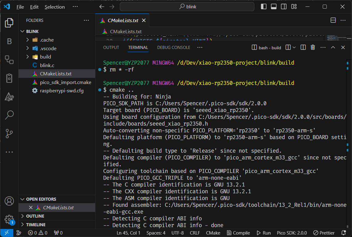
这将允许扩展的编译任务正常工作。
- 编译项目
- 运行项目
现在您可以按下编译按钮来构建项目。这将在build文件夹中生成blink.uf2文件,您可以将其拖放到计算机识别的RP2350驱动器中。
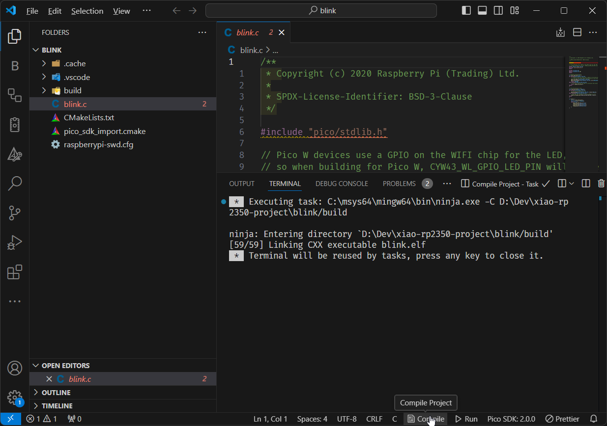
如果您的设备处于BOOT模式,您可以按下运行按钮来编译并自动将.uf2文件复制到RP2350,无需手动拖放文件。
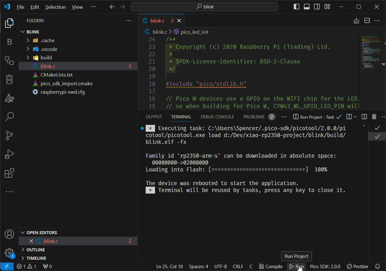
我们刚刚设置了开发环境,并使用VSCode的Raspberry Pi Pico扩展成功创建了一个新项目。项目准备就绪,工具配置完成后,您可以轻松地在XIAO RP2350上编译和运行代码,简化您的开发流程。
示例1:LED闪烁
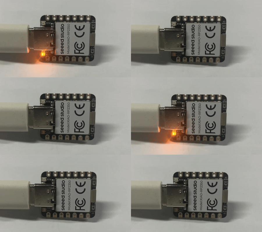
为了演示SDK的基本用法,以下示例详细介绍了如何编程板载LED使其闪烁:
#include "pico/stdlib.h"

const int sleep_time = 250;

int main() {
    const uint LED_PIN = PICO_DEFAULT_LED_PIN; // GPIO25
    gpio_init(LED_PIN);
    gpio_set_dir(LED_PIN, GPIO_OUT);
    while (true) {
        gpio_put(LED_PIN, 1);
        sleep_ms(sleep_time);
        gpio_put(LED_PIN, 0);
        sleep_ms(sleep_time);
    }
}
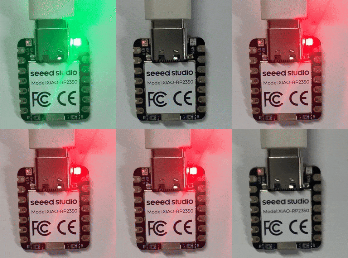
示例 2:RGB 闪烁
- ws2812.c
- ws2812.pio
- CMakeLists.txt
/**
 * Copyright (c) 2020 Raspberry Pi (Trading) Ltd.
 *
 * SPDX-License-Identifier: BSD-3-Clause
 */

#include <stdio.h>
#include <stdlib.h>

#include "pico/stdlib.h"
#include "hardware/pio.h"
#include "hardware/clocks.h"
#include "ws2812.pio.h"

#define IS_RGBW true
#define NUM_PIXELS 1

#ifdef PICO_DEFAULT_WS2812_PIN
#define WS2812_PIN PICO_DEFAULT_WS2812_PIN
#else
// default to pin 2 if the board doesn't have a default WS2812 pin defined
#define WS2812_PIN 22
#endif

static inline void put_pixel(uint32_t pixel_grb) {
    pio_sm_put_blocking(pio0, 0, pixel_grb << 8u);
}

static inline uint32_t urgb_u32(uint8_t r, uint8_t g, uint8_t b) {
    return
            ((uint32_t) (r) << 8) |
            ((uint32_t) (g) << 16) |
            (uint32_t) (b);
}

void pattern_snakes(uint len, uint t) {
    for (uint i = 0; i < len; ++i) {
        uint x = (i + (t >> 1)) % 64;
        if (x < 10)
            put_pixel(urgb_u32(0xff, 0, 0));
        else if (x >= 15 && x < 25)
            put_pixel(urgb_u32(0, 0xff, 0));
        else if (x >= 30 && x < 40)
            put_pixel(urgb_u32(0, 0, 0xff));
        else
            put_pixel(0);
    }
}

void pattern_random(uint len, uint t) {
    if (t % 8)
        return;
    for (int i = 0; i < len; ++i)
        put_pixel(rand());
}

void pattern_sparkle(uint len, uint t) {
    if (t % 8)
        return;
    for (int i = 0; i < len; ++i)
        put_pixel(rand() % 16 ? 0 : 0xffffffff);
}

void pattern_greys(uint len, uint t) {
    int max = 100; // let's not draw too much current!
    t %= max;
    for (int i = 0; i < len; ++i) {
        put_pixel(t * 0x10101);
        if (++t >= max) t = 0;
    }
}

typedef void (*pattern)(uint len, uint t);
const struct {
    pattern pat;
    const char *name;
} pattern_table[] = {
        {pattern_snakes,  "Snakes!"},
        {pattern_random,  "Random data"},
        {pattern_sparkle, "Sparkles"},
        {pattern_greys,   "Greys"},
};

int main() {
    //set_sys_clock_48();
    stdio_init_all();

    const int RGB_POWER = 23;
    gpio_init(RGB_POWER);
    gpio_set_dir(RGB_POWER, GPIO_OUT);
    gpio_put(RGB_POWER, 1);

    printf("WS2812 Smoke Test, using pin %d", WS2812_PIN);

    // todo get free sm
    PIO pio = pio0;
    int sm = 0;
    uint offset = pio_add_program(pio, &ws2812_program);

    ws2812_program_init(pio, sm, offset, WS2812_PIN, 800000, IS_RGBW);

    int t = 0;
    while (1) {
        int pat = rand() % count_of(pattern_table);
        int dir = (rand() >> 30) & 1 ? 1 : -1;
        puts(pattern_table[pat].name);
        puts(dir == 1 ? "(forward)" : "(backward)");
        for (int i = 0; i < 1000; ++i) {
            pattern_table[pat].pat(NUM_PIXELS, t);
            sleep_ms(10);
            t += dir;
        }
    }
}
;
; Copyright (c) 2020 Raspberry Pi (Trading) Ltd.
;
; SPDX-License-Identifier: BSD-3-Clause
;

.program ws2812
.side_set 1

.define public T1 2
.define public T2 5
.define public T3 3

.lang_opt python sideset_init = pico.PIO.OUT_HIGH
.lang_opt python out_init     = pico.PIO.OUT_HIGH
.lang_opt python out_shiftdir = 1

.wrap_target
bitloop:
    out x, 1       side 0 [T3 - 1] ; Side-set still takes place when instruction stalls
    jmp !x do_zero side 1 [T1 - 1] ; Branch on the bit we shifted out. Positive pulse
do_one:
    jmp  bitloop   side 1 [T2 - 1] ; Continue driving high, for a long pulse
do_zero:
    nop            side 0 [T2 - 1] ; Or drive low, for a short pulse
.wrap

% c-sdk {
#include "hardware/clocks.h"

static inline void ws2812_program_init(PIO pio, uint sm, uint offset, uint pin, float freq, bool rgbw) {

    pio_gpio_init(pio, pin);
    pio_sm_set_consecutive_pindirs(pio, sm, pin, 1, true);

    pio_sm_config c = ws2812_program_get_default_config(offset);
    sm_config_set_sideset_pins(&c, pin);
    sm_config_set_out_shift(&c, false, true, rgbw ? 32 : 24);
    sm_config_set_fifo_join(&c, PIO_FIFO_JOIN_TX);

    int cycles_per_bit = ws2812_T1 + ws2812_T2 + ws2812_T3;
    float div = clock_get_hz(clk_sys) / (freq * cycles_per_bit);
    sm_config_set_clkdiv(&c, div);

    pio_sm_init(pio, sm, offset, &c);
    pio_sm_set_enabled(pio, sm, true);
}
%}

.program ws2812_parallel

.define public T1 2
.define public T2 5
.define public T3 3

.wrap_target
    out x, 32
    mov pins, !null [T1-1]
    mov pins, x     [T2-1]
    mov pins, null  [T3-2]
.wrap

% c-sdk {
#include "hardware/clocks.h"

static inline void ws2812_parallel_program_init(PIO pio, uint sm, uint offset, uint pin_base, uint pin_count, float freq) {
    for(uint i=pin_base; i<pin_base+pin_count; i++) {
        pio_gpio_init(pio, i);
    }
    pio_sm_set_consecutive_pindirs(pio, sm, pin_base, pin_count, true);

    pio_sm_config c = ws2812_parallel_program_get_default_config(offset);
    sm_config_set_out_shift(&c, true, true, 32);
    sm_config_set_out_pins(&c, pin_base, pin_count);
    sm_config_set_set_pins(&c, pin_base, pin_count);
    sm_config_set_fifo_join(&c, PIO_FIFO_JOIN_TX);

    int cycles_per_bit = ws2812_parallel_T1 + ws2812_parallel_T2 + ws2812_parallel_T3;
    float div = clock_get_hz(clk_sys) / (freq * cycles_per_bit);
    sm_config_set_clkdiv(&c, div);

    pio_sm_init(pio, sm, offset, &c);
    pio_sm_set_enabled(pio, sm, true);
}
%}
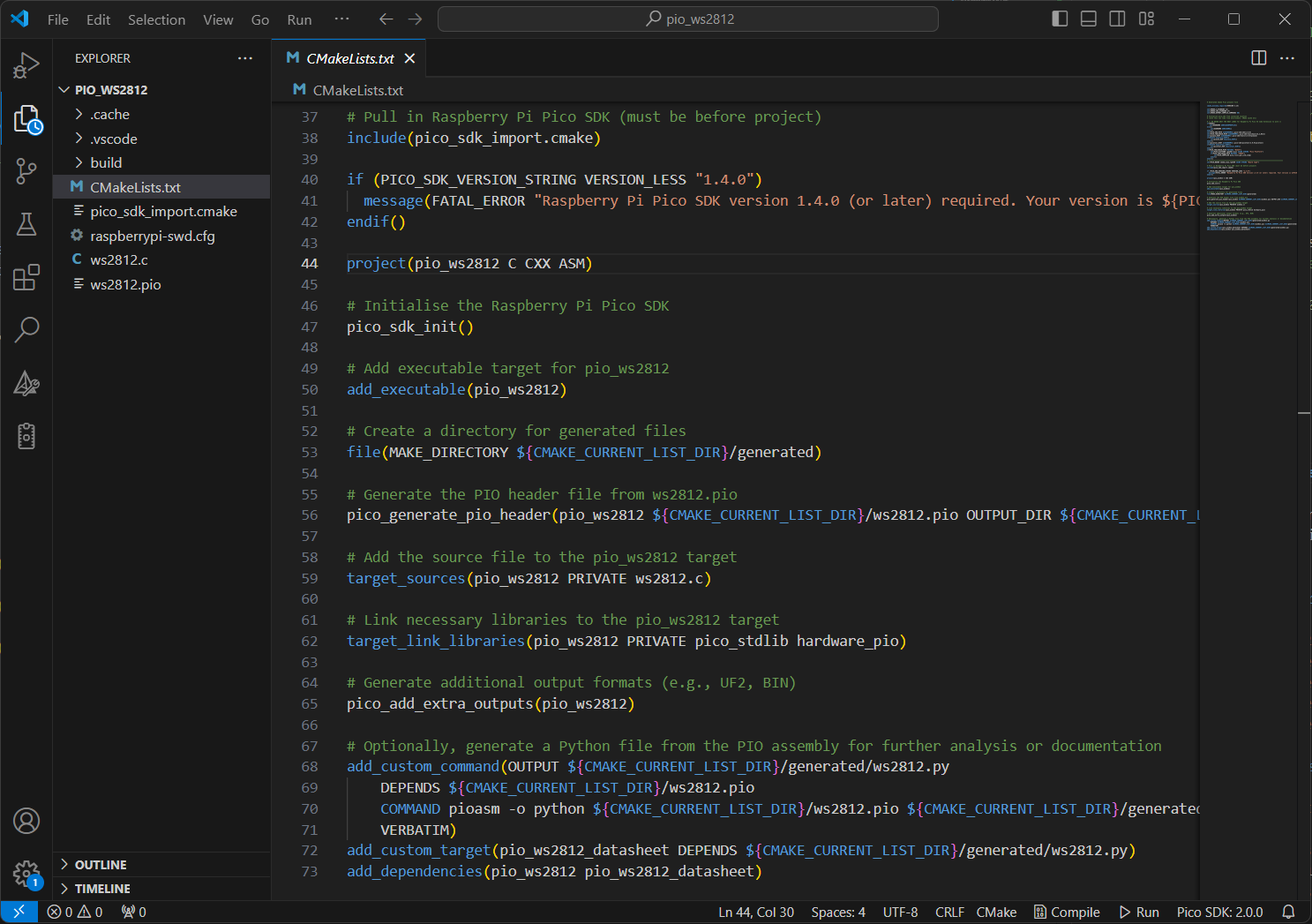
复制以下代码片段并将其附加到您的 CMakeLists.txt 文件中。
project(pio_ws2812 C CXX ASM)

# Initialise the Raspberry Pi Pico SDK
pico_sdk_init()

# Add executable target for pio_ws2812
add_executable(pio_ws2812)

# Create a directory for generated files
file(MAKE_DIRECTORY ${CMAKE_CURRENT_LIST_DIR}/generated)

# Generate the PIO header file from ws2812.pio
pico_generate_pio_header(pio_ws2812 ${CMAKE_CURRENT_LIST_DIR}/ws2812.pio OUTPUT_DIR ${CMAKE_CURRENT_LIST_DIR}/generated)

# Add the source file to the pio_ws2812 target
target_sources(pio_ws2812 PRIVATE ws2812.c)

# Link necessary libraries to the pio_ws2812 target
target_link_libraries(pio_ws2812 PRIVATE pico_stdlib hardware_pio)

# Generate additional output formats (e.g., UF2, BIN)
pico_add_extra_outputs(pio_ws2812)

# Optionally, generate a Python file from the PIO assembly for further analysis or documentation
add_custom_command(OUTPUT ${CMAKE_CURRENT_LIST_DIR}/generated/ws2812.py
    DEPENDS ${CMAKE_CURRENT_LIST_DIR}/ws2812.pio
    COMMAND pioasm -o python ${CMAKE_CURRENT_LIST_DIR}/ws2812.pio ${CMAKE_CURRENT_LIST_DIR}/generated/ws2812.py
    VERBATIM)
add_custom_target(pio_ws2812_datasheet DEPENDS ${CMAKE_CURRENT_LIST_DIR}/generated/ws2812.py)
add_dependencies(pio_ws2812 pio_ws2812_datasheet)
示例 3:UART 打印
如果您想通过 USB 将 printf 输出到您的计算机,您需要在项目的 CMakeLists.txt 文件中添加以下行来配置:
pico_enable_stdio_usb(your_project_name 1)
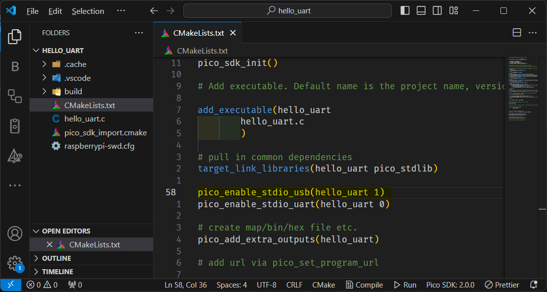
此外,确保在您的代码中通过在主函数中添加 stdio_init_all(); 来初始化标准 I/O。
#include "hardware/uart.h"
#include "pico/stdlib.h"
#include <pico/stdio.h>
#include <pico/time.h>
#include <stdio.h>

#define UART_ID uart0
#define BAUD_RATE 115200

// We are using pins 0 and 1, but see the GPIO function select table in the
// datasheet for information on which other pins can be used.
#define UART_TX_PIN 0
#define UART_RX_PIN 1

int main() {
   stdio_init_all();
  // Set up our UART with the required speed.
  uart_init(UART_ID, BAUD_RATE);

  // Set the TX and RX pins by using the function select on the GPIO
  // Set datasheet for more information on function select
  gpio_set_function(UART_TX_PIN, UART_FUNCSEL_NUM(UART_ID, UART_TX_PIN));
  gpio_set_function(UART_RX_PIN, UART_FUNCSEL_NUM(UART_ID, UART_RX_PIN));

  // Use some the various UART functions to send out data
  // In a default system, printf will also output via the default UART

  // Send out a character without any conversions
  uart_putc_raw(UART_ID, 'A');

  // Send out a character but do CR/LF conversions
  uart_putc(UART_ID, 'B');

  // Send out a string, with CR/LF conversions
  uart_puts(UART_ID, " Hello, UART!\n");

  // Print test
  int i = 0;
  for (;;) {
    sleep_ms(500);
    printf("Hello %d", i++);
  }
}
Exmaple 4: Read Battery Voltage
#include <stdio.h>
#include "pico/stdlib.h"
#include "hardware/gpio.h"
#include "hardware/adc.h"

void init_gpio() {
    const int gpio = 19;

    gpio_init(gpio);
    gpio_set_dir(gpio, GPIO_OUT);
    gpio_put(gpio, 1);
}

int main() {
    stdio_init_all();
    printf("ADC battery Example - GPIO29 A3\n");

    init_gpio();
    adc_init();

    // Make sure GPIO is high-impedance, no pullups etc
    adc_gpio_init(29);
    // Select ADC input 0 (GPIO26)
    adc_select_input(3);

    while (1) {
        // 12-bit conversion, assume max value == ADC_VREF == 3.3 V
        const float conversion_factor = 3.3f / (1 << 12);
        uint16_t result = adc_read();
        printf("Raw value: 0x%03x, voltage: %f V\n", result, result * conversion_factor * 2);
        sleep_ms(500);
    }
}
常见问题
TinyUSB 子模块未初始化;USB 支持不可用
问题: 在构建项目时,您可能会看到此警告:
TinyUSB submodule has not been initialized; USB support will be unavailable
解决方案:
-
在 Linux/macOS 上打开终端,或在 Windows 上打开命令提示符/PowerShell/Git Bash。
-
导航到 Pico SDK 目录:
cd /path/to/your/pico-sdk -
初始化子模块:
git submodule update --init
这将在您的项目中启用USB支持。
资源
- 🔗 [链接] Raspberry Pi Pico SDK | GitHub
- 📄 [PDF] Raspberry Pi Pico系列 C/C++ SDK 记录SDK API的书籍
- 📄 [PDF] Raspberry Pi Pico系列入门指南 - 官方Raspberry Pi文档。
- 📽️ [视频] Raspberry Pi Pico和RP2040介绍 - 视频教程。
技术支持与产品讨论
感谢您选择我们的产品!我们在这里为您提供不同的支持,以确保您使用我们产品的体验尽可能顺畅。我们提供多种沟通渠道,以满足不同的偏好和需求。