Seeed Studio XIAO ESP32C5 Zigbee 快速入门指南(Arduino)
本教程指导您在 Seeed Studio XIAO ESP32-C5 开发板上实现 Zigbee 应用,该开发板结合了 Wi-Fi、低功耗蓝牙(BLE) 和 Zigbee 连接功能,非常适合 物联网应用。本指南中的示例使用 esp-arduino Zigbee SDK 来实现 Zigbee 功能。

如果您还没有准备好 Arduino IDE,请参考 入门指南。
Zigbee 概述
Zigbee 是一种基于 IEEE 802.15.4 标准的 低功耗、低带宽 无线通信协议。它专为 家庭自动化、智慧城市 和 工业控制 等物联网场景量身定制,提供强大的网状网络功能,在动态环境中实现可靠通信。
- 我们将简要介绍 Zigbee 相关内容。如果您想直接参考应用示例,也可以跳过这部分。
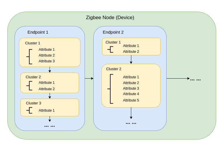
Zigbee 数据模型
Zigbee 通信依赖于 Zigbee 集群库(ZCL),它定义了设备如何组织其功能并进行交互。关键组件包括:
-
设备类型 Zigbee 设备(例如开关、传感器、灯具)具有预定义的特定行为,按功能分组到 集群 中。
-
集群 集群是以下内容的逻辑分组:
- 属性:表示设备状态,如亮度或温度。
- 命令:触发动作,如打开灯或将亮度设置为 50%。
示例:
- 开/关集群:控制二进制状态,如电源。
- 电平控制集群:调节强度或亮度。
- 温度测量集群:发送温度读数。
- 场景集群:保存和调用预设配置。
-
属性和命令 属性存储设备数据(例如状态、配置),而命令启动操作。
Zigbee 网络架构
Zigbee 网络由三种主要节点类型组成:
-
Zigbee 协调器(ZC)
- 作为网络的中央枢纽。
- 处理网络创建、设备认证和地址分配。
- 负责初始化和管理网络。
- 每个 Zigbee 网络只能有 一个协调器。
-
Zigbee 路由器(ZR)
- 通过在设备之间中继消息来扩展网络范围。
- 支持更多设备加入网络。
- 通常使用市电供电以确保持续运行和可靠的消息中继。
- 电池供电的路由器是可能的,但由于能耗较高而不太常见。
-
Zigbee 终端设备(ZED)
- 轻量级且节能的设备,与父节点(协调器或路由器)通信。
- 不向其他设备路由消息。
- 针对电池操作进行优化,通常进入睡眠模式以节约能源。
-
寻址和路由:
- Zigbee 使用 16 位寻址方案。设备通过直接和间接寻址的混合方式进行通信。
- 路由决策由路由器使用 AODV(按需距离矢量)等算法做出。
-
电源管理:
- Zigbee 终端设备针对低功耗进行了优化。它们通常在睡眠模式下运行,只在需要时唤醒。
- 路由器和协调器通常使用市电供电以确保持续可用性。
网络拓扑
Zigbee 支持三种主要的网络拓扑,具体取决于应用需求和环境:
1. 网状拓扑
-
一个协调器和多个路由器形成自愈、强健的网络。
-
如果通信路径中断,设备可以动态重新路由消息,确保高可靠性。
-
适用于需要广泛覆盖和冗余的大规模网络。
-
主要特性:
- 动态重新路由确保高可靠性。
- 支持具有可扩展覆盖范围的大型网络。
- 自愈机制提高容错能力。
2. 树状拓扑
-
协调器作为分层结构的根,路由器形成分支。
-
每个分支可以有多个终端设备或额外的路由器,创建树状结构。
-
通信依赖于分层路径,这会引入潜在的单点故障。
-
主要特性:
- 适用于结构化环境。
- 比网状网络更容易设置和管理。
- 容易受到分支故障影响,可能导致整个子网络断开连接。
3. 星状拓扑
-
所有设备直接与协调器通信。
-
部署简单,但协调器是单点故障。
-
最适合设备靠近协调器的小型网络。
-
主要特性:
- 易于设置和管理。
- 由于范围和设备容量限制,可扩展性有限。
- 依赖协调器进行所有通信,降低了容错能力。
Arduino Zigbee 入门
我们将在 Arduino IDE 中使用 XIAO ESP32-C5 上的 Zigbee_On_Off_Light 和 Zigbee_On_Off_Switch 为您演示 Zigbee 网络功能。
硬件准备
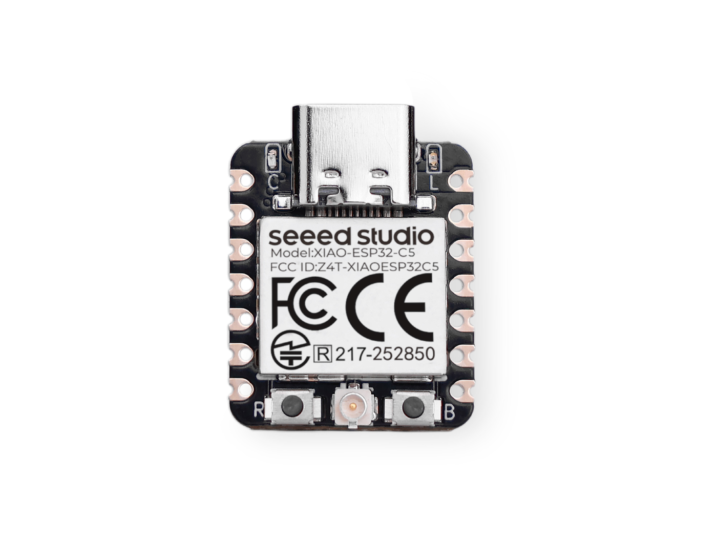
您需要准备两块 XIAO ESP32-C5 开发板。
| Seeed Studio XIAO ESP32-C5 |
|---|
 |
Zigbee_On_Off_Light
您需要选择一块 XIAO ESP32-C5 作为灯泡设备。
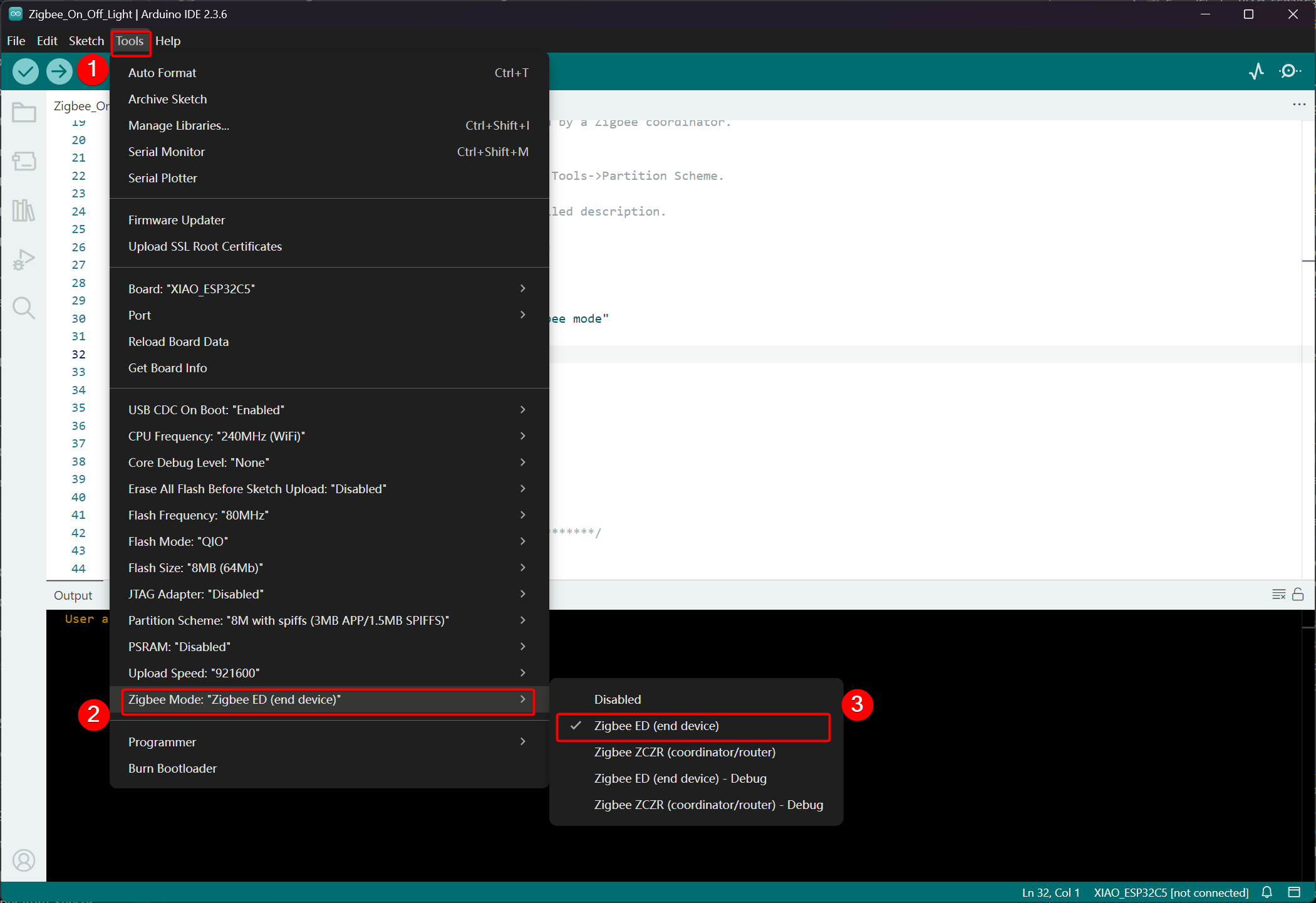
步骤 1. 设置终端设备模式
我们需要将 XIAO ESP32-C5 设置为 Zigbee 终端设备。
- 点击 Tools -> Zigbee Mode 并选择模式为 Zigbee ED (End Device)。
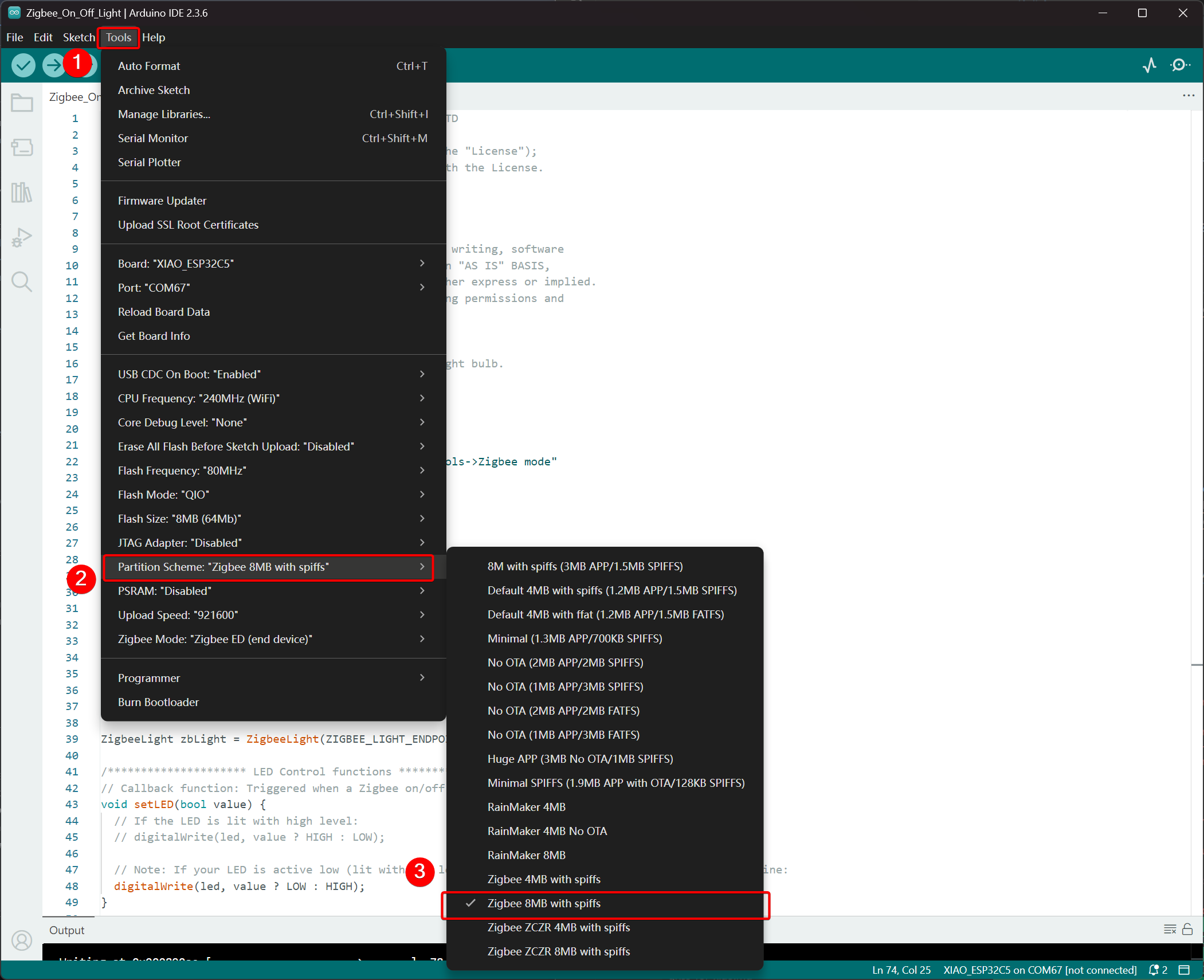
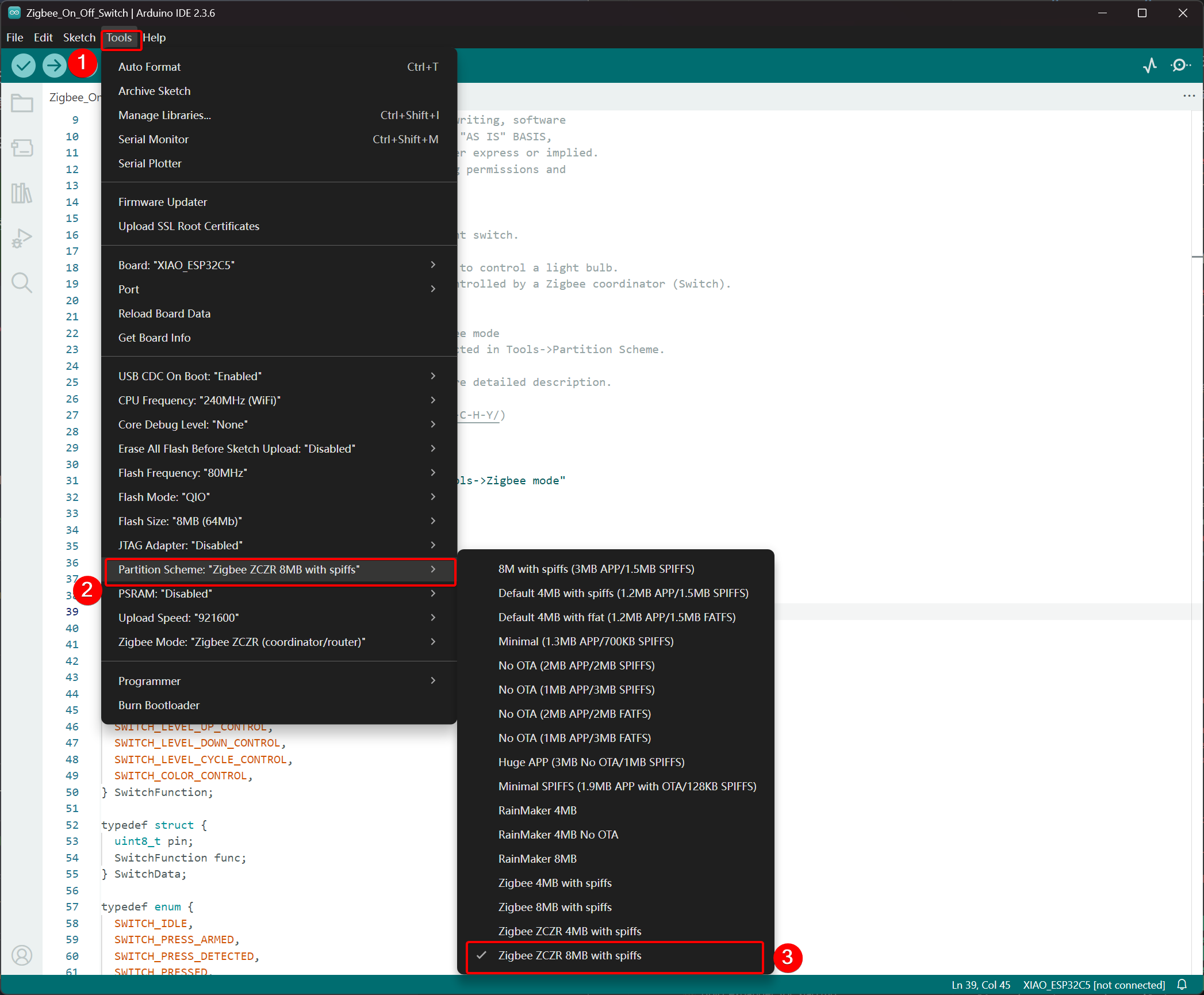
- 选择分区方案,转到 Tools -> Partition Scheme -> Zigbee 8MB with spiffs
XIAO ESP32-C5 的 FLASH 内存为 8MB。选择分区方案时,建议选择 Zigbee 8MB with spiffs。
步骤 2. 编写代码
- 参考官方 Arduino 仓库获取示例。
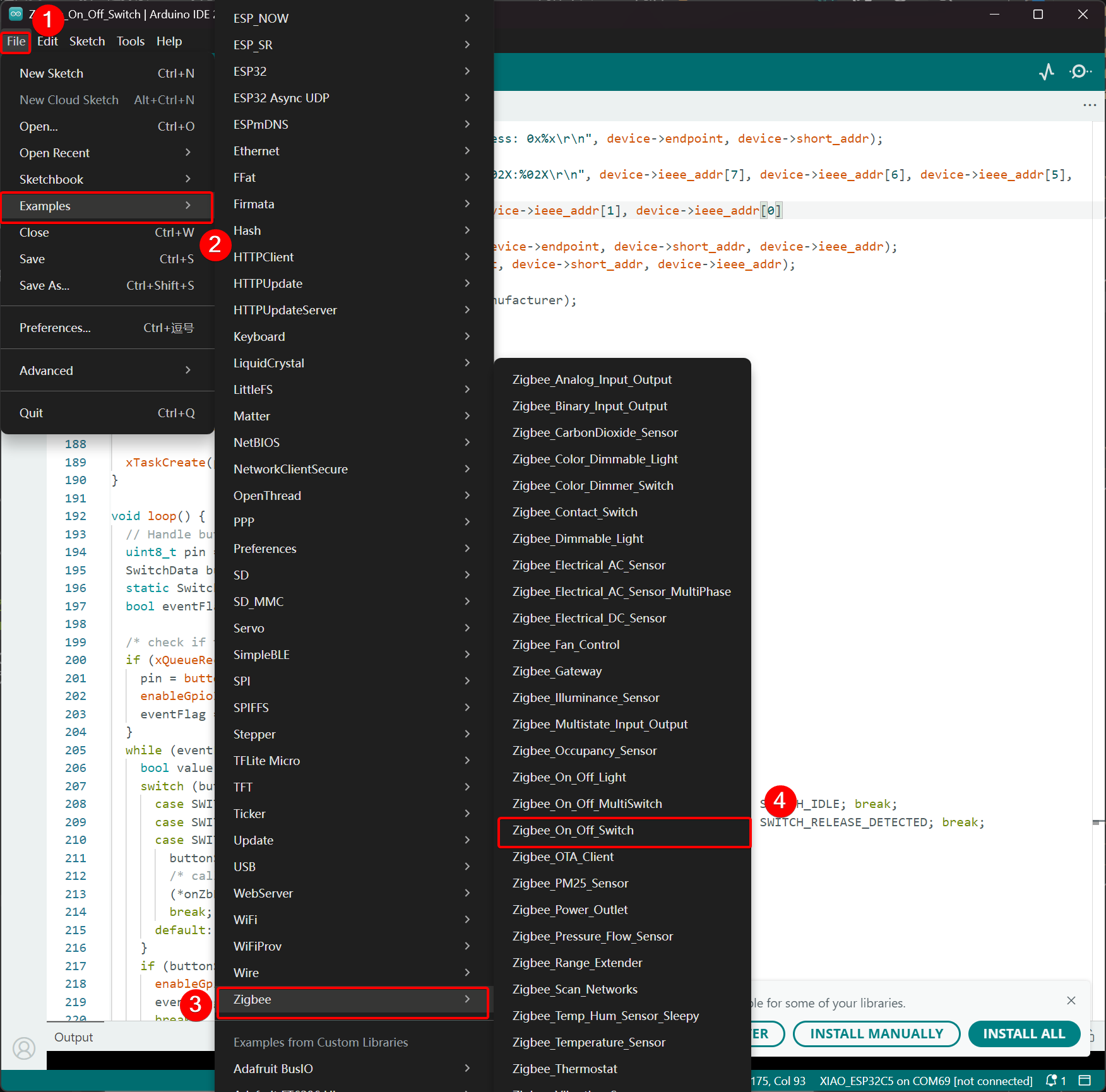
- 或者,您可以通过以下路径从 Arduino IDE 中选择示例:File -> Examples -> Zigbee -> Zigbee_On_Off_Light。

- 修改示例
对于 XIAO ESP32-C5,我们选择板载 LED 作为发光灯泡,控制引脚是 GPIO27。
Zigbee_On_Off_Light.ino
// Copyright 2024 Espressif Systems (Shanghai) PTE LTD
//
// Licensed under the Apache License, Version 2.0 (the "License");
// you may not use this file except in compliance with the License.
// You may obtain a copy of the License at

//     http://www.apache.org/licenses/LICENSE-2.0
//
// Unless required by applicable law or agreed to in writing, software
// distributed under the License is distributed on an "AS IS" BASIS,
// WITHOUT WARRANTIES OR CONDITIONS OF ANY KIND, either express or implied.
// See the License for the specific language governing permissions and
// limitations under the License.

/**
 * @brief This example demonstrates simple Zigbee light bulb.
 *
 * Modified for Single Color LED control.
 */

#ifndef ZIGBEE_MODE_ED
#error "Zigbee end device mode is not selected in Tools->Zigbee mode"
#endif

#include "Zigbee.h"

/* Zigbee light bulb configuration */
#define ZIGBEE_LIGHT_ENDPOINT 10

// =========================================================
// Modification Area: Define your single-color LED pin here
// If your LED is connected to GPIO 2, set it to 2.
// If using the onboard standard LED, LED_BUILTIN can usually be used
// =========================================================
uint8_t led = 27;  // <--- Please modify the number here to your actual GPIO pin number

uint8_t button = BOOT_PIN;

ZigbeeLight zbLight = ZigbeeLight(ZIGBEE_LIGHT_ENDPOINT);

/********************* LED Control functions **************************/
// Callback function: Triggered when a Zigbee on/off command is received
void setLED(bool value) {
  // If the LED is lit with high level:
  // digitalWrite(led, value ? HIGH : LOW);

  // Note: If your LED is active low (lit with low level), use the line below instead of the above line:
  digitalWrite(led, value ? LOW : HIGH);
}

/********************* Arduino functions **************************/
void setup() {
  Serial.begin(115200);

  // Initialize LED pin as output mode
  pinMode(led, OUTPUT);
  // Turn off LED by default (assuming low level means on)
  digitalWrite(led, LOW);

  // Initialize button for factory reset
  pinMode(button, INPUT_PULLUP);

  // Optional: Set Zigbee device name and model (will be displayed in Home Assistant)
  zbLight.setManufacturerAndModel("Espressif", "SingleColorLight");

  // Set callback function for light state change
  zbLight.onLightChange(setLED);

  // Add Endpoint to Zigbee core
  Serial.println("Adding ZigbeeLight endpoint to Zigbee Core");
  Zigbee.addEndpoint(&zbLight);

  // Start Zigbee
  if (!Zigbee.begin()) {
    Serial.println("Zigbee failed to start!");
    Serial.println("Rebooting...");
    ESP.restart();
  }
  Serial.println("Connecting to network");
  while (!Zigbee.connected()) {
    Serial.print(".");
    delay(100);
  }
  Serial.println();
}

void loop() {
  // Check button for factory reset
  if (digitalRead(button) == LOW) {  // Button is pressed
    // Button debounce
    delay(100);
    int startTime = millis();
    while (digitalRead(button) == LOW) {
      delay(50);
      if ((millis() - startTime) > 3000) {
        // If pressed for more than 3 seconds, reset Zigbee and reboot
        Serial.println("Resetting Zigbee to factory and rebooting in 1s.");
        delay(1000);
        Zigbee.factoryReset();
      }
    }
    // Short press of the button: Toggle light state (local control)
    zbLight.setLight(!zbLight.getLightState());
  }
  delay(100);
}
- 上传代码。 由于默认设置为低电平点亮,上传代码后按下复位按钮,板载 LED 将会亮起。
实现逻辑
- 模式检查
#ifndef ZIGBEE_MODE_ED
#error "Zigbee end device mode is not selected..."
#endif
这强制在 Arduino IDE 的 Tools → Zigbee mode 中选择 "End Device" 模式。Zigbee 灯泡通常作为低功耗终端设备,而不是路由器或协调器。
- 包含头文件
#include "Zigbee.h"
导入 Espressif 提供的核心 Zigbee 库,其中包含所有 Zigbee 相关的类和函数。
- 配置定义
#define ZIGBEE_LIGHT_ENDPOINT 10
将 Zigbee 端点号定义为 10。一个 Zigbee 设备可以有多个端点,这里将灯泡功能分配给端点 10。
- 用户可修改区域(最重要的部分)
uint8_t led = 27;        // Modify this to the actual GPIO pin connected to your LED
uint8_t button = BOOT_PIN;  // Usually GPIO0, used for factory reset
-
led = 27:控制单色 LED 的 GPIO 引脚。请根据您的硬件接线修改此数字。 -
button = BOOT_PIN:通常是 ESP32 开发板上的 BOOT 按钮(GPIO0),用于长按重置 Zigbee 配置。
- 创建 Zigbee 灯泡对象
ZigbeeLight zbLight = ZigbeeLight(ZIGBEE_LIGHT_ENDPOINT);
创建一个 Zigbee Light 对象,实现标准的 Zigbee HA(家庭自动化)OnOff 集群,支持远程开关控制。
- LED 控制回调函数
void setLED(bool value) {
  digitalWrite(led, value ? LOW : HIGH);
}
当从 Zigbee 网络接收到开关命令时,此函数会自动调用。
- 当前代码假设您的 LED 是低电平有效(当 ESP32 开发板上的外部 LED 通过电阻连接到 GND 时很常见)。
- 如果您的 LED 是高电平有效(例如,直接连接到 VCC 并通过拉低 GPIO 点亮),请修改为下面注释的行:
digitalWrite(led, value ? HIGH : LOW);
- setup() 函数详细说明
void setup() {
  Serial.begin(115200);                    // Enable serial debugging with baud rate 115200

  pinMode(led, OUTPUT);                    // Set the LED pin as output
  digitalWrite(led, LOW);                  // Turn off the LED by default (assuming active low, write LOW to ensure it's off)

  pinMode(button, INPUT_PULLUP);           // Set the button pin as input with pull-up resistor

  zbLight.setManufacturerAndModel("Espressif", "SingleColorLight");
  // Set the device manufacturer and model for friendly display on platforms like Home Assistant

  zbLight.onLightChange(setLED);
  // Key step: Bind the callback function for switch state changes, which calls setLED() when a Zigbee command is received

  Zigbee.addEndpoint(&zbLight);
  // Add the bulb endpoint to the Zigbee core

  if (!Zigbee.begin()) { ... ESP.restart(); }
  // Start the Zigbee stack; restart if it fails

  while (!Zigbee.connected()) { ... }
  // Wait for successful joining of the Zigbee network (pairing completed), print a dot every 100ms
}
- loop() 函数详细说明
void loop() {
  if (digitalRead(button) == LOW) {        // Detect button press (low level)
    delay(100);                            // Simple debounce
    int startTime = millis();

    while (digitalRead(button) == LOW) {   // Continuously detect if the button is still pressed
      if ((millis() - startTime) > 3000) { // Long press for more than 3 seconds
        Zigbee.factoryReset();             // Factory reset Zigbee configuration (clear pairing information)
        delay(1000);
        // The device will automatically restart and enter pairing mode again
      }
    }

    // If short press: manually control the light's on/off state locally
    zbLight.setLight(!zbLight.getLightState());
    // This triggers the callback setLED() simultaneously to turn the light on/off locally
  }

  delay(100);
}
Zigbee_On_Off_Switch
选择另一个 XIAO ESP32-C5 作为开关。它将与之前的灯泡设备组成 Zigbee 网络,然后控制灯泡的开关状态。
步骤 1. 设置为协调器模式
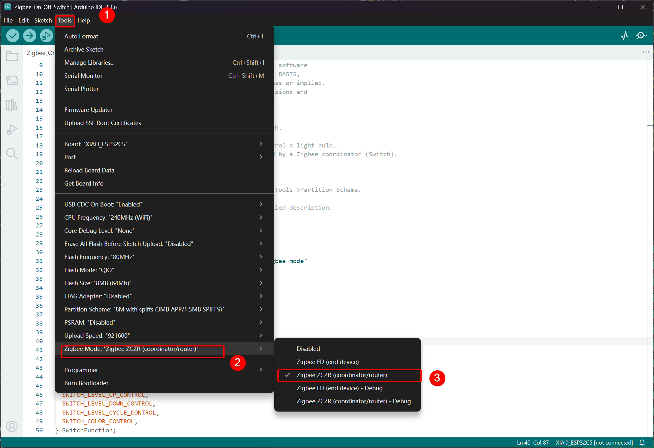
- 点击 Tools -> Zigbee Mode 并选择模式为 Zigbee ZCZR (Coordinator/Router)。
- 选择分区方案,转到 Tools -> Partition Scheme 并选择 Zigbee 8MB ZCZR with spiffs。
XIAO ESP32-C5 的 FLASH 内存为 8MB。选择分区方案时,建议选择 Zigbee 8MB ZCZR with spiffs。
步骤 2. 编写代码
- 跳转到官方 Arduino 仓库获取示例代码。
- 或者,您可以通过以下路径从 Arduino IDE 中选择示例:File -> Examples -> Zigbee -> Zigbee_On_Off_Swicth。
- 我们选择 BOOT 按钮作为开关。对于 XIAO ESP32-C5,BOOT 按钮对应 GPIO28 引脚。
Zigbee_On_Off_Switch.ino
// Copyright 2024 Espressif Systems (Shanghai) PTE LTD
//
// Licensed under the Apache License, Version 2.0 (the "License");
// you may not use this file except in compliance with the License.
// You may obtain a copy of the License at
//
//     http://www.apache.org/licenses/LICENSE-2.0
//
// Unless required by applicable law or agreed to in writing, software
// distributed under the License is distributed on an "AS IS" BASIS,
// WITHOUT WARRANTIES OR CONDITIONS OF ANY KIND, either express or implied.
// See the License for the specific language governing permissions and
// limitations under the License.

/**
 * @brief This example demonstrates simple Zigbee light switch.
 *
 * The example demonstrates how to use Zigbee library to control a light bulb.
 * The light bulb is a Zigbee end device, which is controlled by a Zigbee coordinator (Switch).
 * Button switch and Zigbee runs in separate tasks.
 *
 * Proper Zigbee mode must be selected in Tools->Zigbee mode
 * and also the correct partition scheme must be selected in Tools->Partition Scheme.
 *
 * Please check the README.md for instructions and more detailed description.
 *
 * Created by Jan Procházka (https://github.com/P-R-O-C-H-Y/)
 */

#ifndef ZIGBEE_MODE_ZCZR
#error "Zigbee coordinator mode is not selected in Tools->Zigbee mode"
#endif

#include "Zigbee.h"

/* Zigbee switch configuration */
#define SWITCH_ENDPOINT_NUMBER 5

#define GPIO_INPUT_IO_TOGGLE_SWITCH BOOT_PIN
#define PAIR_SIZE(TYPE_STR_PAIR)    (sizeof(TYPE_STR_PAIR) / sizeof(TYPE_STR_PAIR[0]))

typedef enum {
  SWITCH_ON_CONTROL,
  SWITCH_OFF_CONTROL,
  SWITCH_ONOFF_TOGGLE_CONTROL,
  SWITCH_LEVEL_UP_CONTROL,
  SWITCH_LEVEL_DOWN_CONTROL,
  SWITCH_LEVEL_CYCLE_CONTROL,
  SWITCH_COLOR_CONTROL,
} SwitchFunction;

typedef struct {
  uint8_t pin;
  SwitchFunction func;
} SwitchData;

typedef enum {
  SWITCH_IDLE,
  SWITCH_PRESS_ARMED,
  SWITCH_PRESS_DETECTED,
  SWITCH_PRESSED,
  SWITCH_RELEASE_DETECTED,
} SwitchState;

static SwitchData buttonFunctionPair[] = {{GPIO_INPUT_IO_TOGGLE_SWITCH, SWITCH_ONOFF_TOGGLE_CONTROL}};

ZigbeeSwitch zbSwitch = ZigbeeSwitch(SWITCH_ENDPOINT_NUMBER);

static bool light_state = false;

/********************* Zigbee functions **************************/
static void onZbButton(SwitchData *button_func_pair) {
  if (button_func_pair->func == SWITCH_ONOFF_TOGGLE_CONTROL) {
    // Send toggle command to the light
    Serial.println("Toggling light");
    zbSwitch.lightToggle();
  }
}

static void onLightStateChange(bool state) {
  if (state != light_state) {
    light_state = state;
    Serial.printf("Light state changed to %d\r\n", state);
  }
}

/********************* Periodic task ***************************/
void periodicTask(void *arg) {
  while (true) {
    // print the bound lights every 10 seconds
    static uint32_t lastPrint = 0;
    if (millis() - lastPrint > 10000) {
      lastPrint = millis();
      zbSwitch.printBoundDevices(Serial);
    }

    // Poll light state every second
    static uint32_t lastPoll = 0;
    if (millis() - lastPoll > 1000) {
      lastPoll = millis();
      zbSwitch.getLightState();
    }
    vTaskDelay(1000 / portTICK_PERIOD_MS);
  }
}

/********************* GPIO functions **************************/
static QueueHandle_t gpio_evt_queue = NULL;

static void IRAM_ATTR onGpioInterrupt(void *arg) {
  xQueueSendFromISR(gpio_evt_queue, (SwitchData *)arg, NULL);
}

static void enableGpioInterrupt(bool enabled) {
  for (int i = 0; i < PAIR_SIZE(buttonFunctionPair); ++i) {
    if (enabled) {
      enableInterrupt((buttonFunctionPair[i]).pin);
    } else {
      disableInterrupt((buttonFunctionPair[i]).pin);
    }
  }
}

/********************* Arduino functions **************************/
void setup() {
  Serial.begin(115200);

  //Optional: set Zigbee device name and model
  zbSwitch.setManufacturerAndModel("Espressif", "ZigbeeSwitch");

  //Optional to allow multiple light to bind to the switch
  zbSwitch.allowMultipleBinding(true);

  zbSwitch.onLightStateChange(onLightStateChange);

  //Add endpoint to Zigbee Core
  Serial.println("Adding ZigbeeSwitch endpoint to Zigbee Core");
  Zigbee.addEndpoint(&zbSwitch);

  //Open network for 180 seconds after boot
  Zigbee.setRebootOpenNetwork(180);

  // Init button switch
  for (int i = 0; i < PAIR_SIZE(buttonFunctionPair); i++) {
    pinMode(buttonFunctionPair[i].pin, INPUT_PULLUP);
    /* create a queue to handle gpio event from isr */
    gpio_evt_queue = xQueueCreate(10, sizeof(SwitchData));
    if (gpio_evt_queue == 0) {
      Serial.println("Queue creating failed, rebooting...");
      ESP.restart();
    }
    attachInterruptArg(buttonFunctionPair[i].pin, onGpioInterrupt, (void *)(buttonFunctionPair + i), FALLING);
  }

  // When all EPs are registered, start Zigbee with ZIGBEE_COORDINATOR mode
  if (!Zigbee.begin(ZIGBEE_COORDINATOR)) {
    Serial.println("Zigbee failed to start!");
    Serial.println("Rebooting...");
    ESP.restart();
  }

  Serial.println("Waiting for Light to bound to the switch");
  //Wait for switch to bound to a light:
  while (!zbSwitch.bound()) {
    Serial.printf(".");
    delay(500);
  }

  // Optional: List all bound devices and read manufacturer and model name
  std::list<zb_device_params_t *> boundLights = zbSwitch.getBoundDevices();
  for (const auto &device : boundLights) {
    Serial.printf("Device on endpoint %d, short address: 0x%x\r\n", device->endpoint, device->short_addr);
    Serial.printf(
      "IEEE Address: %02X:%02X:%02X:%02X:%02X:%02X:%02X:%02X\r\n", device->ieee_addr[7], device->ieee_addr[6], device->ieee_addr[5], device->ieee_addr[4],
      device->ieee_addr[3], device->ieee_addr[2], device->ieee_addr[1], device->ieee_addr[0]
    );
    char *manufacturer = zbSwitch.readManufacturer(device->endpoint, device->short_addr, device->ieee_addr);
    char *model = zbSwitch.readModel(device->endpoint, device->short_addr, device->ieee_addr);
    if (manufacturer != nullptr) {
      Serial.printf("Light manufacturer: %s\r\n", manufacturer);
    }
    if (model != nullptr) {
      Serial.printf("Light model: %s\r\n", model);
    }
  }

  Serial.println();

  xTaskCreate(periodicTask, "periodicTask", 1024 * 4, NULL, 10, NULL);
}

void loop() {
  // Handle button switch in loop()
  uint8_t pin = 0;
  SwitchData buttonSwitch;
  static SwitchState buttonState = SWITCH_IDLE;
  bool eventFlag = false;

  /* check if there is any queue received, if yes read out the buttonSwitch */
  if (xQueueReceive(gpio_evt_queue, &buttonSwitch, portMAX_DELAY)) {
    pin = buttonSwitch.pin;
    enableGpioInterrupt(false);
    eventFlag = true;
  }
  while (eventFlag) {
    bool value = digitalRead(pin);
    switch (buttonState) {
      case SWITCH_IDLE:           buttonState = (value == LOW) ? SWITCH_PRESS_DETECTED : SWITCH_IDLE; break;
      case SWITCH_PRESS_DETECTED: buttonState = (value == LOW) ? SWITCH_PRESS_DETECTED : SWITCH_RELEASE_DETECTED; break;
      case SWITCH_RELEASE_DETECTED:
        buttonState = SWITCH_IDLE;
        /* callback to button_handler */
        (*onZbButton)(&buttonSwitch);
        break;
      default: break;
    }
    if (buttonState == SWITCH_IDLE) {
      enableGpioInterrupt(true);
      eventFlag = false;
      break;
    }
    vTaskDelay(10 / portTICK_PERIOD_MS);
  }
}
- 上传代码并打开串口监视器;网络信息将被打印出来。最终效果请跳转到结果
实现逻辑
- 模式检查
#ifndef ZIGBEE_MODE_ZCZR
#error "Zigbee coordinator mode is not selected in Tools->Zigbee mode"
#endif
此示例中的开关充当 Zigbee 协调器(ZC/ZR),负责组建网络并控制其他设备。
- 包含头文件
#include "Zigbee.h"
导入 Espressif 提供的核心 Zigbee 库,包含 Zigbee 操作所需的所有类和函数。
- 配置定义
#define SWITCH_ENDPOINT_NUMBER 5
#define GPIO_INPUT_IO_TOGGLE_SWITCH BOOT_PIN
SWITCH_ENDPOINT_NUMBER 5:定义 Zigbee 开关功能使用的端点号(5)。GPIO_INPUT_IO_TOGGLE_SWITCH BOOT_PIN:将物理按钮引脚设置为 BOOT 引脚(通常是 GPIO0)。此按钮将触发切换动作。
- 数据结构和按钮配置
typedef enum { ... } SwitchFunction;
typedef struct { uint8_t pin; SwitchFunction func; } SwitchData;

static SwitchData buttonFunctionPair[] = {{GPIO_INPUT_IO_TOGGLE_SWITCH, SWITCH_ONOFF_TOGGLE_CONTROL}};
- 定义可能的开关功能(切换、开启、关闭、电平控制等)。
buttonFunctionPair数组将物理引脚映射到其功能。目前只配置了一个按钮:BOOT 引脚在按下时执行切换操作。
- 创建 Zigbee 开关对象
ZigbeeSwitch zbSwitch = ZigbeeSwitch(SWITCH_ENDPOINT_NUMBER);
创建一个 ZigbeeSwitch 对象,实现标准的 Zigbee 开/关开关设备,能够通过 Zigbee 绑定向绑定的灯泡发送命令。
- Zigbee 回调函数
static void onZbButton(SwitchData *button_func_pair) {
  if (button_func_pair->func == SWITCH_ONOFF_TOGGLE_CONTROL) {
    zbSwitch.lightToggle();  // Send toggle command to all bound lights
  }
}

static void onLightStateChange(bool state) {
  // Called when a bound light reports a state change
  Serial.printf("Light state changed to %d\r\n", state);
}
onZbButton:当检测到有效按钮按下时执行;向所有绑定的灯发送切换命令。onLightStateChange:当任何绑定的灯报告其新的开/关状态时触发的回调(用于同步)。
- 周期性任务
void periodicTask(void *arg) {
  while (true) {
    // Every 10 seconds: print all currently bound devices
    // Every 1 second: poll the current state of bound lights
    vTaskDelay(1000 / portTICK_PERIOD_MS);
  }
}
一个独立的 FreeRTOS 任务,定期打印绑定设备信息并轮询灯的状态以保持协调器同步。
- GPIO 中断和队列处理
static QueueHandle_t gpio_evt_queue = NULL;

static void IRAM_ATTR onGpioInterrupt(void *arg) {
  xQueueSendFromISR(gpio_evt_queue, (SwitchData *)arg, NULL);
}
- 使用 FreeRTOS 队列安全地将按钮按下事件从 ISR(中断服务程序)传递到主循环。
- 中断附加到按钮引脚的下降沿以实现快速检测。
- setup() 函数详细说明
void setup() {
  Serial.begin(115200);

  zbSwitch.setManufacturerAndModel("Espressif", "ZigbeeSwitch");
  zbSwitch.allowMultipleBinding(true);  // Allow controlling multiple lights simultaneously
  zbSwitch.onLightStateChange(onLightStateChange);

  Zigbee.addEndpoint(&zbSwitch);

  Zigbee.setRebootOpenNetwork(180);  // Open network for pairing for 180 seconds after boot

  // Initialize button pins and attach interrupts
  pinMode(... , INPUT_PULLUP);
  attachInterruptArg(... , FALLING);

  if (!Zigbee.begin(ZIGBEE_COORDINATOR)) { ... ESP.restart(); }

  // Block until at least one light is bound
  while (!zbSwitch.bound()) { Serial.print("."); delay(500); }

  // Print detailed information about all bound lights (address, manufacturer, model)
  zbSwitch.printBoundDevices(Serial);

  // Create periodic task
  xTaskCreate(periodicTask, "periodicTask", 1024 * 4, NULL, 10, NULL);
}
- 配置开关设备属性并允许多重绑定。
- 开放网络 180 秒以便于灯泡的轻松配对。
- 以协调器模式启动 Zigbee。
- 等待至少一个灯成功绑定,然后打印详细的绑定信息。
- 启动周期性监控任务。
- loop() 函数详细说明
void loop() {
  // Receive button events from queue
  if (xQueueReceive(gpio_evt_queue, &buttonSwitch, portMAX_DELAY)) {
    // Disable further interrupts to prevent bounce interference
    enableGpioInterrupt(false);

    // State machine for reliable button detection:
    // - Detect press → confirm sustained press → detect release → execute action
    static SwitchState buttonState = SWITCH_IDLE;
    // ... state transitions ...

    if (buttonState == SWITCH_IDLE) {
      // Button fully released → execute toggle command
      onZbButton(&buttonSwitch);
      // Re-enable interrupts for next press
      enableGpioInterrupt(true);
    }
  }
}
- 使用状态机实现强大的防抖按钮处理器。
- 确保在发送切换命令之前完成完整的按下和释放周期。
- 在处理期间防止中断重入以实现稳定操作。
结果
将两个 XIAO ESP32-C5 开发板连接到您的计算机并打开串口监视器。如果灯泡设备打印 Connecting to network,表示它已加入 Zigbee 网络,开关设备将打印已加入网络的设备信息。当您按下开关设备上的 BOOT 按钮时,灯泡设备的板载 USER LED 将切换。
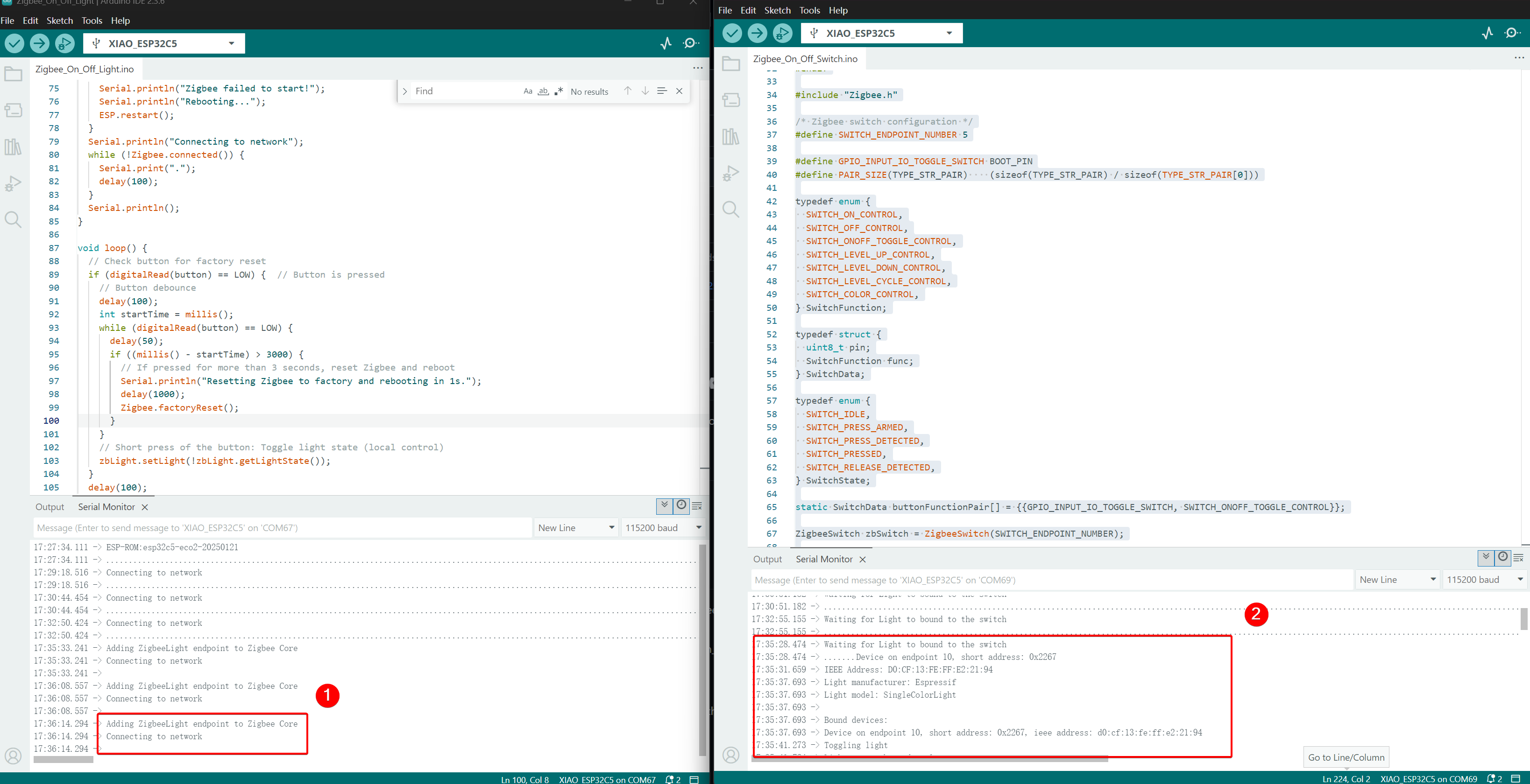
- 控制效果,当按下 BOOT 按钮时,另一个 XIAO ESP32-C5 上的 USER LED 将切换。
技术支持与产品讨论
感谢您选择我们的产品!我们在这里为您提供不同的支持,以确保您使用我们产品的体验尽可能顺畅。我们提供多种沟通渠道,以满足不同的偏好和需求。